
Create successful ePaper yourself
Turn your PDF publications into a flip-book with our unique Google optimized e-Paper software.
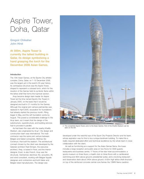
<strong>Aspire</strong> <strong>Tower</strong>,<br />
<strong>Doha</strong>, <strong>Qatar</strong><br />
Gregoir Chikaher<br />
John Hirst<br />
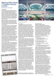
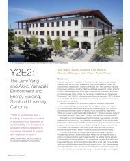
At 300m, <strong>Aspire</strong> <strong>Tower</strong> is<br />
currently the tallest building in<br />
<strong>Qatar</strong>, its design symbolizing a<br />
hand grasping the torch for the<br />
December 2006 Asian Games.<br />
Introduction<br />
The 15th Asian Games, at the Sports City athletic<br />
complex, <strong>Doha</strong>, <strong>Qatar</strong>, on 1-15 December 2006,<br />
was the largest yet in the event’s 55-year history.<br />
Its centrepiece structure was the <strong>Aspire</strong> <strong>Tower</strong>,<br />
shaped to represent a colossal torch, which for the<br />
duration of the Games held its symbolic flame within<br />
the lattice shell that forms the topmost section.<br />
<strong>Arup</strong> became design team leader for <strong>Aspire</strong><br />
<strong>Tower</strong> (at the time named Sports City <strong>Tower</strong>) in<br />
January 2005, on the basis that it would be<br />
designed and built in 21 months for the Games.<br />
Although the original joint venture partnership was<br />
replaced in April 2005, excavation for foundations<br />
had already started the previous month. Piling<br />
began in May, and the raft foundation works by<br />
August. This posed a considerable challenge to the<br />
<strong>Arup</strong> team, as it meant that the design of the<br />
substructure, superstructure, and building services<br />
had to proceed in parallel.<br />
As had been the case with the nearby Khalifa<br />
Stadium, also engineered by <strong>Arup</strong>1 , the design and<br />
construction team was international. The main<br />
contractor was the same joint venture between<br />
Belgian and <strong>Qatar</strong>i companies, Midmac-Six<br />
Construct, that built the stadium. The architectural<br />
concept chosen by the client was developed by the<br />
<strong>Qatar</strong>ian architect Hadi Simaan, the executive<br />
architect, Arep, is based in Paris, and the interior<br />
designer, Ecart, is also French. <strong>Arup</strong> was the<br />
structural, mechanical, electrical, fire, acoustics, lift,<br />
and wind consultant, working with Belgian façade<br />
designers and contractors and both Italian and<br />
Belgian steel manufacturers. The design was<br />
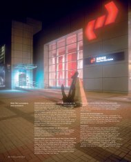
2. The completed <strong>Aspire</strong> <strong>Tower</strong>, prior to the Asian Games. Part of the Khalifa Stadium can be<br />
seen on the left.<br />
developed under the watchful eye of the Sport City Projects Director and his team,<br />
whose aspiration was for this to be a unique landmark building. To make this a<br />
reality required dedicated effort and technical excellence by the whole team in close<br />
collaboration with the client.<br />
As well as functioning as a support for the Asian Games flame, the tower<br />
includes a large reception and public area on two floors for 3000 guests;<br />
restaurants and business centre; 17 floors of five-star hotel accommodation; a<br />
sports museum on three floors; a health club on three floors with a cantilevered<br />
swimming pool 80m above ground; presidential suites; and a revolving restaurant<br />
and observation deck about 240m above ground. A 62m high lattice shell structure<br />
on top of the reinforced concrete central core frames the 15MW flame cauldron.<br />
The <strong>Arup</strong> Journal 2/2007 3
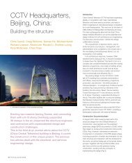
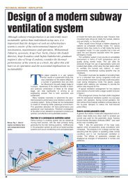
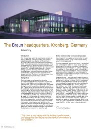
4<br />
Revolving<br />
restaurant<br />
Presidential suites<br />
Restaurants,<br />
business centre,<br />
and sports<br />
museum<br />
3. Principal elements of the tower.<br />
4. The flame cauldron and lattice shell structure.<br />
The <strong>Arup</strong> Journal 2/2007<br />
15MW flame cauldron<br />
Observation deck<br />
Health club<br />
Swimming pool<br />
Five-star<br />
hotel<br />
Reception<br />
and public<br />
area<br />
Building summary<br />
The concrete core has a minimum external diameter of 13m, a maximum diameter<br />
of 18m, and walls 1-2m thick. It reaches 238m above ground and is surmounted by<br />
a cone that supports the flame cauldron, shrouded by the lattice shell structure.<br />
The core forms the building’s backbone, and supports the clusters (modules) of<br />
accommodation floors and the external envelope. Each cluster cantilevers up to<br />
11.3m from the core independently, with no columns to the ground. The health<br />
club’s cantilevered swimming pool at the 19th floor extends beyond the floor plate<br />
by over 12m.<br />
The building envelope wraps around the core to achieve maximum efficiency,<br />
and rises as a sheer structure clad in an energy-efficient outer glass skin, with<br />
environmental systems that achieve comfort levels in the occupied spaces even<br />
when outside temperatures exceed 40°C. High-speed lifts shuttle guests to the<br />
observation deck, bar, and revolving restaurant. In addition, 140 tonnes of tuned<br />
mass damper (TMD) at the top of the tower ensure comfort to patrons enjoying<br />
Arabic hospitality in the revolving restaurant, against the dry, hot Khamsin winds.<br />
The tower is designed to carry over 71 000 tonnes of load and is supported by<br />
a 37.3m diameter raft up to 7m thick, working in conjunction with 77 straight<br />
shafted piles.<br />
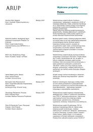
5. <strong>Aspire</strong> <strong>Tower</strong> at night, showing the cantilevered swimming pool.
6. Hotel floors under construction behind glazed façade.<br />
Foundations<br />
A geotechnical desk study, which included information from the Khalifa Stadium,<br />
indicated sound limestone near to ground level, so the initial design was based on<br />
a raft foundation. While this progressed, a site investigation was made of the<br />
deeper geology and rock types - particularly important in view of the magnitude<br />
and concentration of load arising from the building form - and this confirmed the<br />
presence of weak Rus Chalk between the limestone strata, with its potential for<br />
voiding and relatively poor rock quality. In view of this and the assessment of<br />
soil/rock stress in this stratum based on the raft design already under way, the<br />
team decided that piling to the raft was needed to ensure adequate load capacity.<br />
Bored cast in situ piles were used, limited to a maximum 1.2m diameter to suit<br />
local practice, and extending through the Rus Chalk to the better quality<br />
limestone below. The piles were cast in grade C32/40 concrete for the<br />
necessary design strength.<br />
The 37.3m raft diameter was determined by the need to spread the entire tower<br />
load delivered by the core, so as to limit bearing pressures to appropriate levels<br />
under the raft, in the Rus Chalk, and on the piles. In addition to gravity loads, the<br />
raft provides resistance to overturning effects under lateral wind and seismic loads.<br />
The arrangement provided also ensures that there is no tension in the piles or uplift,<br />
as the tension effects of overturning are balanced against the vertical load from the<br />
tower’s self-weight.<br />
The raft thickness was derived on the basis of the same loading parameters,<br />
with the central area 7m thick to deal with the total core load, and a reduced<br />
thickness of 4m towards the perimeter where load is shed into the ground.<br />
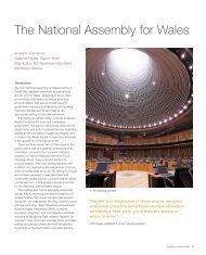
Piled raft analysis<br />
A family of analysis models was used to determine the force effects for the raft<br />
structural design, with the Oasys interactive soil/structure program, GSRaft, being<br />
employed to analyze the foundation system.<br />
This uses an iterative analysis system between two models, one for structure<br />
and one for soil. The structure model comprises a GSA grillage model (Fig 7)<br />
supported on springs at the underside of the raft and also at pile positions at the<br />
depth of the pile load transfer length. The soil model comprises a representation of<br />
the soil strata, with loaded areas corresponding to spring location in the structure<br />
model. At each stage of iteration soil settlements are calculated by another Oasys<br />
program, Vdisp, for the spring loads in the structure model. The settlements are<br />
then used to reset the spring stiffnesses in the structure model. The process is<br />
continued until vertical movements and load distributions match, providing a unique<br />
analysis for each load condition.<br />
To assess local effects such as load spread beneath the core walls, the through<br />
thickness flexibility of the raft over an annular sector was modelled axisymetrically,<br />
using loads and spring stiffnesses output by GSRaft. A lower/upper bound design<br />
approach allowed for the range of parameters involved - soil, concrete, design<br />
loads, etc.<br />
Pile springs at load transfer level<br />
below weak layer of ground<br />
7. GSRaft grillage model.<br />
C L<br />
raft<br />
Core wall<br />
8. GSA axisymmetric model.<br />
Pile spring stiffness from GSRaft<br />
9. Pouring the 7m thick raft foundation.<br />
Raft springs at formation level<br />
The <strong>Arup</strong> Journal 2/2007 5
6<br />
The core<br />
The core’s internal diameter at the base is 14m,<br />
reducing to 11m at the restaurant level. The full core<br />
terminates at the viewing gallery level, above which<br />
a concrete frame transfers lateral and vertical loads<br />
from the steel lattice shell back to the top of the<br />
core. This was analyzed for serviceability and<br />
strength under vertical and wind loading by a full<br />
dynamic method based on wind engineering data<br />
from the advisory body ESDU (originally Engineering<br />
Sciences Data Unit). The Ritz method2 was used for<br />
the modal analysis to calculate the natural<br />
frequencies. The along-wind response of the tower<br />
was critical, as the crosswind effects due to vortex<br />
shedding are reduced by the presence of<br />
permeable mesh cladding rather than solid<br />
perimeter cladding.<br />
A seismic analysis based on the 1997 Uniform<br />
Building Code3 , Zone 1, showed that seismic<br />
loading was not critical to the stability design, and<br />
so this was determined by the wind loading.<br />
The vertical reinforcement in the core walls,<br />
designed in accordance with British Standard<br />
BS81104 , generally varies between 0.4-0.9% of the<br />
section area. This was based on the tower’s<br />
aerodynamic properties investigated through wind<br />
tunnel testing. The following effects were<br />
considered as the design progressed:<br />
• moments induced due to local bending arising<br />
from steps in the core profile<br />
• radial loads/moments from transfer systems to<br />
hotel, museum, health club, and restaurant<br />
• anchoring the steel lattice for the top of the<br />
building<br />
• restraint to the perimeter cladding system<br />
• openings in the core and coupling beam<br />
arrangements.<br />
The predicted peak displacement at the<br />
restaurant level from a 50-year wind was 454mm,<br />
or the height of the core from foundation level<br />
divided by 472. The predicted building accelerations<br />
from wind with return periods between one and 100<br />
years are not within “acceptable” limits for 0.7%<br />
damping, which was assessed as the natural<br />
damping inherent within the building’s structural<br />
stability system. A TMD was therefore proposed to<br />
achieve a total of some 2% damping and reduce<br />
accelerations to acceptable levels.<br />
The <strong>Arup</strong> Journal 2/2007<br />
Superstructure floors<br />
The floors that cantilever out from the central core comprise steel beams<br />
supporting concrete slabs acting compositely with metal decking. The general<br />
arrangement has the primary beams spanning radially between steel columns and<br />
the core, with circumferential secondary beams. Steel columns in each module are<br />
supported by transfer arrangements cantilevering from the core. The presidential<br />
apartments, museum, and restaurant floors are supported off the core by steel<br />
cantilever brackets at the base of each accommodation block; these brackets also<br />
support the external cladding.<br />
The lower viewing platform floor is similarly supported, while the upper viewing<br />
platform floor is in reinforced concrete cantilevering directly from the top of the core.<br />
The hotel, by contrast, is supported off the core by a system of vertical trusses<br />
located within the partition walls between the hotel rooms. The inner lines of the<br />
vertical trusses are in turn supported at their bases by a reinforced concrete corbel<br />
10. Concrete core under construction, March 2006.
11. Upper hotel floors, August 2006.<br />
ring to the core located below level 4 in the hotel lobby area. The vertical trusses<br />
are typically between levels 5 and 10. An additional level of wall bracing (between<br />
levels 10 and 11) was needed under the lift lobby and the swimming pool in order<br />
to deal with the greater loads at these locations.<br />
The tower is entirely clad in stainless steel mesh, including the “voids” between<br />
the accommodation modules, so as to provide a unifying surface for the entire<br />
building. The mesh acts in catenary and is prestressed within individual frames that<br />
span vertically between horizontal ring trusses at approximately 8m vertical spacing.<br />
The cladding is horizontally restrained either directly by the structural floors, or by<br />
an arrangement of struts connected to the floors. In the areas between floors, the<br />
cladding is restrained by an arrangement of struts connected directly to the core.<br />
The weight of the perimeter cladding is supported by the same transfer<br />
structures that support the main floors. The cladding is both bottom supported and<br />
top hung, with horizontal movement joints provided between modules of cladding<br />
to accommodate differential vertical movement.<br />
323<br />
12. Floor support bracket.<br />
Transfer<br />
beam<br />
Façade<br />
support<br />
13. Upper hotel/office and health club.<br />
14. Hotel floor support.<br />
Swimming pool<br />
support truss<br />
Additional<br />
bracing<br />
below pool<br />
The <strong>Arup</strong> Journal 2/2007 7
8<br />
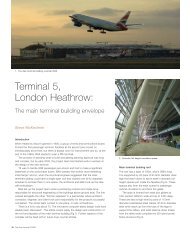
15. Swimming pool support truss in place.<br />
16. Original design for the pool support truss.<br />
17. Deflection of the steel supporting structure and the total combined stresses (ultimate values). 18. Internal core detail.<br />
258.4N/mm 2<br />
236.4<br />
174.5<br />
112.5<br />
50.62<br />
-11.31<br />
-73.24<br />
-135.20<br />
The <strong>Arup</strong> Journal 2/2007<br />
Deformation<br />
magnification: 7.813<br />
Combined stress C1<br />
500N/mm2 Swimming pool<br />
The swimming pool is elliptical on plan: 11m long,<br />
6m wide, about 50m2 in area, and 1.5m deep. It is<br />
a reinforced concrete box with 0.3m thick walls,<br />
supported on a substantial steel truss structure<br />
some 4m deep, to correspond to the storey height<br />
containing the pool. The plan geometry of the truss<br />
is straight from the core to the column locations,<br />
and then elliptical with approximately the same<br />
shape as the pool. The truss is connected to the<br />
core and supported on two columns that continue<br />
down through the levels below, which are supported<br />
on the vertical trusses previously described.<br />
As the pool and deck area extend about 12m<br />
from the tower perimeter, the support positions for<br />
the truss are as close to the perimeter as possible<br />
to minimize the distance to be cantilevered and<br />
maximize the extension. The truss system was<br />
designed to allow the pool itself to extend 8m from<br />
the support columns with the deck area protruding<br />
a further 4m.<br />
The steel structure was erected first, to provide<br />
primary support and a frame within which the<br />
concrete for the pool itself could be cast in situ.<br />
The steel structure and supports were designed to<br />
resist lateral loads and therefore required bracing to<br />
transfer loads back to the core. The pool weighs<br />
about 300 tonnes in total, of which the steel<br />
supporting structure represents just above 10%<br />
(approximately 35 tonnes).<br />
Internal core<br />
Inside the central core are access stairs, lift shafts,<br />
landings, and service risers (Fig 18). The primary<br />
internal walls are of reinforced concrete, with<br />
reinforced concrete stairs cast in situ. The design<br />
allowed for open-mesh access floors to the services<br />
risers, and additional secondary support steelwork<br />
was required to support lift guide rails, etc.<br />
In situ reinforced concrete<br />
lobby/landing slabs<br />
Open mesh flooring<br />
on service risers<br />
as neccesary<br />
Reinforced<br />
concrete<br />
inner walls<br />
Reinforced<br />
concrete<br />
stairs
a) Site welded<br />
fin plate<br />
b)<br />
Tie rods<br />
Cast-in<br />
plate<br />
Sleeves in<br />
core wall<br />
Pocket in<br />
slipformed<br />
wall<br />
Corbel cast<br />
into pocket<br />
19. Initial concepts for a) core connection detail (with tension capacity) and b) strut support<br />
corbel detail.<br />
Connections to the core<br />
The <strong>Arup</strong> team discussed with the contractor how the steel beams should be<br />
connected to the core, which was slipformed throughout its height, including the<br />
corbel section at low level and the frame at the viewing gallery level. Steel plates<br />
were cast into the wall at floor beam locations and anchored back into the body of<br />
the core. These embedded plates were surveyed and connections for the floor and<br />
transfer beams were welded on site.<br />
Damping<br />
Assessment of the building’s performance indicated that additional damping would<br />
be needed to reduce lateral accelerations at the top under wind loading and so<br />
improve comfort levels. A feasibility study of various options for a total of 2% critical<br />
damping indicated that a TMD directly below the highest viewing level was the most<br />
practical solution for the range of predicted frequencies, and so a 140 tonne (active<br />
mass) folded-pendulum TMD with a steel mass was installed within the tower core.<br />
Fine tuning to the tower’s measured natural frequency was achieved by adjusting<br />
the pendulum lengths. The “fold” in the pendulum reduced the height of the<br />
required envelope by about half, but needed a rigid frame to transfer the tension<br />
between the first and second stage members. Shaping the TMD mass in this way<br />
facilitated fitting the damper within the circular plan shape of the core (Fig 20).<br />
The detailed design, manufacture, testing and tuning of the TMD container was<br />
undertaken by a specialist contractor. Energy dissipation of the TMD is achieved by<br />
“pot dampers” which also incorporate bumper stops to prevent excess movement<br />
of the mass in extreme situations.<br />
Cladding support systems<br />
As already noted, the whole tower is clad in stainless steel mesh of varying<br />
permeability, apart from the bottom few metres. The hotel lobby, up to some 63m,<br />
is fully glazed within the outer mesh surface; this glazing is subject to wind load,<br />
and has significant thermal performance requirements as the upper levels of the<br />
hotel lobby get hot. Apart from the mesh and the hotel lobby glazing, the rest of the<br />
cladding is fairly conventional. It typically spans floor-to-floor (typically 4.05m apart),<br />
either directly or with supporting mullions.<br />
JAP, the Belgian cladding supplier, proposed supporting the lobby mesh<br />
cladding and glazing in panels typically 8.1m high (ie two hotel storey heights), with<br />
six panels for each 20° of circumference giving a total of 108 panels on plan. The<br />
even number of subdivisions gives greater planning flexibility as it allows the use of<br />
the half grid. Above the lobby, the number of mesh panels was reduced to three for<br />
each 20° segment, ie 54 in plan for the total circumference. In the hotel lobby zone<br />
the external mesh and the glass are separated by about 1m. JAP proposed to link<br />
the frames carrying the mesh and glass to form a truss supporting a maintenance<br />
walkway. To reduce the number of struts here, the truss was designed to span one<br />
ninth of the circumference. Where the large cladding panels or the lobby trusses<br />
connect to the struts, movement joints are provided to avoid thermal stresses.<br />
Internal diameter<br />
of core 11m at<br />
+234.5m<br />
a)<br />
b)<br />
20. Folded pendulum TMD.<br />
Edge of TMD<br />
envelope<br />
Pendulum<br />
frame<br />
21. Detail of support for façade mesh.<br />
7m<br />
First stage pendulum<br />
(rod or cable)<br />
Second stage pendulum<br />
(rod or cable)<br />
5m<br />
The <strong>Arup</strong> Journal 2/2007 9
22. The diagrid and flame support, October 2006.<br />
The top of the building<br />
Structural elements<br />
The 62m high steel diagrid frame tops out at 300m<br />
above the reference external ground level. The diagrid<br />
forms the lateral stability system for this part of the<br />
building, and also supports the cladding down to the<br />
restaurant floors. The diagrid springs from a substantial<br />
concrete frame: a 1m wide and 1.5m deep<br />
circumferential ring beam supported by nine concrete<br />
columns each approximately 1m by 1.5m arranged<br />
radially on top of the concrete core wall. The top of the<br />
concrete core wall is approximately 233.3m above<br />
lobby level, the top of the frame some 4.5m above that.<br />
The primary loadbearing elements are the circular<br />
hollow sections (CHS) that form the diagrid shell, which<br />
vary from 610mm diameter near the base to 457mm<br />
diameter at the top. The shell is restrained laterally by a<br />
series of horizontal trusses outside the “petal” at 8.1m<br />
vertical centres, spaced to coincide with the cladding<br />
system’s horizontal support elements and sized to<br />
accept horizontal loads from it. The upper levels of<br />
trusses are in 500mm x 200mm rectangular hollow<br />
sections (RHS) and 300mm x 300mm square hollow<br />
sections (SHS), while the lower levels have 300mm x<br />
300mm SHS.<br />
The vertical loads in the outer plane of the structure, ie<br />
just inside the cladding line, are carried by 18 hangers,<br />
120mm x 120mm SHS, equally spaced around the<br />
building perimeter. The outer booms of the trusses<br />
span between them for vertical load, whilst they restrain<br />
the truss booms against buckling out of plane. At the<br />
head of the outer plane there is an “eaves trimmer” -<br />
23. Structural elements of the diagrid frame and b) ring beam support for diagrid.<br />
a)<br />
The diagrid<br />
shell<br />
10 The <strong>Arup</strong> Journal 2/2007<br />
Horizontal<br />
trusses<br />
the rim of the “petal” - formed from 610mm diameter<br />
CHS. It carries the vertical load in the hangers,<br />
spanning between the heads of the diagrid elements<br />
and acting in biaxial bending to resolve the forces in the<br />
diagrid elements that do not node out regularly at the<br />
ring. In addition the eaves trimmer carries wind load<br />
and/or vertical load from the cladding connected<br />
directly to it.<br />
The diagrid is a tall, relatively light structure that is<br />
subject to significant lateral loads. As a result,<br />
substantial tension forces are generated within it under<br />
some load situations. The steel structure is well able to<br />
deal with these, but this behaviour also gave rise to the<br />
potential for physical uplift and considerable movement<br />
of the base of the shell from the supporting structure.<br />
To cater for this effect, the base of the lattice shell is<br />
attached to the top of the core by clusters of vertical<br />
prestressed bars extending down into the body of the<br />
core. these clusters consist of either four or six<br />
prestressed bars, each stressed up to 3200kN, and<br />
anchoring 300mm thick baseplates of the lattice shell<br />
nodes to the supporting concrete. Installing these bars<br />
and the associated anchor plates, ducts, and antibursting<br />
reinforcement was a considerable challenge<br />
for the contractor.<br />
Structural action<br />
Vertical loads<br />
At the diagrid rim, the hanger loads are collected by the<br />
eaves trimmer. This is curved in plan and elevation, so<br />
there is no direct line-up between the hangers and the<br />
diagrid members. The eaves trimmer must therefore<br />
carry torsion as well as bending moments in two<br />
directions, shear in two directions, and axial force.<br />
The splice connections in the eaves trimmer are bolted<br />
connections offset from the diagrid members. The<br />
diagrid CHSs then carry the loads in compression to<br />
the head of the core where they are resisted by the<br />
bearing of the connection nodes onto a grout layer on<br />
the head of the core walls.<br />
The building’s asymmetrical shape means that the<br />
cladding and self-weight loads on the high side are<br />
significantly greater than on the low side. In addition to<br />
the overall compression, this generates an overall<br />
bending moment in the diagrid shell system, carried in<br />
the same way as the moments generated by wind load<br />
in the wide direction.<br />
Horizontal loads applied in the wide direction<br />
This is the critical direction for wind loading because (a)<br />
the widest face area is exposed to the wind, and (b) the<br />
structural depth available to resist the loads is at a<br />
minimum.<br />
The wind applies pressure to the cladding system,<br />
which spans 8.1m vertically between horizontal trusses.<br />
The horizontal trusses collect and redistribute the<br />
horizontal component of the wind load and transfer it to<br />
Vertical<br />
hangers<br />
The rim of<br />
the “petal”<br />
the petal diagrid, which resists by push/pull action in<br />
the inclined CHS members and transfers it down to the<br />
connection at the head of the core. Each level of<br />
horizontal truss contributes to the push/pull in the<br />
diagrid CHSs and so the magnitude of the forces in the<br />
diagrid increases down the structure until it reaches a<br />
maximum in the level immediately above the head of<br />
the core. The forces distribute themselves elastically<br />
through the grid structure so that there are<br />
compressions on the downwind side of the shell<br />
structure, tensions on the upwind side, and opposing<br />
pairs of compressions and tensions in between.<br />
This is analogous to a vertical cantilevering action in an<br />
idealized beam element.<br />
Axial shortening of the compression elements and<br />
extension of the tension elements lead to an overall<br />
downwind deflection of the top of the structure - its<br />
most significant deflection mode. Elements were sized<br />
to limit this deflection and keep its effect on the racking<br />
of the cladding panels within reasonable limits.<br />
Horizontal loads in the narrow direction<br />
The structure works similarly for narrow direction wind<br />
but, as the loaded profile is narrower, the overall loads<br />
on the diagrid are less. Also, the width of diagrid<br />
perpendicular to the load direction is greater, so the<br />
push/pull action resists loads more efficiently. However<br />
the eccentricity of the centre of action of the load does<br />
give rise to an overall torsion in the diagrid in addition<br />
to the overall bending. This is resisted by the diagrid<br />
just as it resists the other shear forces, by push/pull<br />
action in the diagonal CHSs.<br />
24. The lattice diagrid, August 2006.<br />
b)
a) Vertical loads. b) Wide direction load resistance.<br />
c) Magnified deflection. d) Narrow direction load resistance.<br />
25. CAD modelling of structural loads.<br />
Axial force, FX<br />
10 000 kN/pic.cm<br />
6224kN<br />
4394<br />
2563<br />
732.8<br />
-1098<br />
-2928<br />
-4758<br />
-6589<br />
Red = tension<br />
Blue = compression<br />
Axial force, FX<br />
10 000 kN/pic.cm<br />
3464kN<br />
2474<br />
1485<br />
494.8<br />
-4948<br />
-1485<br />
-2474<br />
-3484<br />
Red = tension<br />
Blue = compression<br />
Vertical loads from the cladding are applied to the outer horizontal booms. The booms span between hangers.<br />
Hangers carry these loads to the eaves trimmer at the rim of the diagrid. Note that the hanger connections<br />
must carry the whole hanging load through the node points.<br />
Wind loading and wind tunnel testing<br />
Meteorological data on wind speeds enabled an analysis of extreme winds to be<br />
undertaken. This analysis indicated a gust reference design wind speed of 38m/sec<br />
to CP3: Chapter V: Part 25 , which was the reference code specified by the client.<br />
This analysis was accepted as the design basis for the tower and allowed a<br />
reduction to the normal reference design wind speed in <strong>Doha</strong>.<br />
Wind tunnel studies were undertaken at a facility run by the specialist company<br />
BMT Fluid Mechanics. These provided aerodynamic design data on which to base<br />
computation of the tower’s response, as well as assessing the potential of a vortex<br />
shedding resonant response.<br />
Overall aerodynamic coefficients were derived from wind tunnel testing, and<br />
were used to review the values adopted in the initial design stage. This permitted a<br />
more accurate assessment of overall structural loads and accelerations at the top<br />
occupied level. Forces were measured on 1:100 scale sectional models of the top<br />
of the tower and a middle section (these being most relevant to the overall<br />
behaviour of the tower). A high-frequency force balance at the base of the models<br />
was used to measure forces on the model. Modelling of the surface mesh was<br />
particularly important, and full size samples were tested together with a scale<br />
representation of the mesh so as to provide appropriate representation on the wind<br />
tunnel model. Aerodynamic coefficients were derived from the measured force<br />
values and the geometry of the tower.<br />
CAD<br />
The tower superstructure was modelled in 3-D using Tekla Structures software.<br />
This provided valuable co-ordination and representation of complex elements,<br />
including the diagrid, where 2-D CAD would clearly have been inadequate.<br />
Building services design<br />
To design and build the 300m tower in 21 months<br />
was a huge challenge. <strong>Qatar</strong>’s desert climate, with<br />
temperatures as high as 50°C in summer, plus<br />
<strong>Doha</strong>’s high humidity levels, make it vital that the<br />
plant and equipment perform to their design<br />
parameters without failing. The building envelope<br />
has to achieve maximum thermal efficiency and<br />
comfort levels in the occupied spaces whilst giving<br />
guests panoramic views of the city. Detailed studies<br />
were carried out, including building physics with<br />
simulation software, to select the best glazing and<br />
mesh properties to reduce overall cooling load and<br />
energy consumption.<br />
The MEP systems were designed to relevant<br />
international standards but incorporate <strong>Qatar</strong> codes<br />
and regulations. The main considerations in <strong>Arup</strong>’s<br />
design of the systems included comfort, reliability,<br />
life safety, energy efficiency, space for plant, and<br />
speed of construction.<br />
The tower’s estimated electrical demand was<br />
7MVA with a peak cooling load of 7MW; two<br />
independent 11kV power supplies are connected to<br />
the network and operate simultaneously to share<br />
the load. Each, however, can supply the full load if<br />
the other fails, to give high resilient power supply for<br />
life safety and hotel operations. 11kV switchrooms<br />
at the basement and revolving restaurant levels act<br />
as nodes for the local 11kV distribution network.<br />
A 350mm diameter chilled water connection links<br />
to the main energy centre with flow and return<br />
temperatures of 6.5°C and 14.5°C respectively, and<br />
a chilled water flow rate of 223 litres/sec. Stand-by<br />
generators serve the life safety equipment, security<br />
systems, commercial operations, and data/<br />
communication systems.<br />
As the tower comprises discrete blocks of<br />
accommodation connected to the central core, the<br />
extent of the MEP services running within the core<br />
was limited so as to speed its construction and<br />
maximize the accommodation space. Only the main<br />
lifts and the chilled water, electrical, and water<br />
installations were located in the core to connect the<br />
health club, museum, and restaurant levels to the<br />
plant in the basement. Each of these includes air<br />
intake and exhaust points for the air-handling units<br />
(AHUs) serving each discrete block.<br />
The chilled water system comprises series of<br />
sealed pressurized circuits, operating on variable<br />
flow to match the anticipated high diversity factor<br />
and reduce energy demand. The building is divided<br />
into four pressure zones: the lowest serving the<br />
basement only, the second up to health club level,<br />
the third up to museum level, and the fourth the<br />
revolving restaurant and observation deck.<br />
The <strong>Arup</strong> Journal 2/2007 11
A<br />
Solar altitude<br />
= 44.2°<br />
Outer skin inclination = 79° (approximately)<br />
26. CFD modelling for air movement and temperature.<br />
27. Environmental zones.<br />
To reduce pressure ratings, a plate heat exchanger at health club level serves the<br />
upper floors. All terminal units and AHUs were designed with two-port control<br />
valves to maintain the required enthalpies. Because of high ambient water<br />
temperatures, the swimming pool water is also cooled by plate heat exchangers to<br />
maintain a temperature of 30°C.<br />
To predict air movement and comfort level, especially for the ground floor lobby<br />
and restaurant areas, a computational fluid dynamics (CFD) model, STAR-CD, was<br />
used to calculate the air temperature distribution and air movement in the atrium.<br />
The light ray tracing software Radiance was used to calculate the direct and diffuse<br />
solar radiation distribution as inputs to the CFD model. This included the complex<br />
transmission, absorption, and reflection properties of the external shading elements<br />
and glass façade combination.<br />
<strong>Arup</strong>’s innovative approach to the mechanical design was to create a two-zone<br />
environment with air supply nozzles mounted around the inner core at level 4 and a<br />
series of binnacles in the lobby area. The low zone was predicted to be well mixed<br />
within the target air temperature range, whilst the high zone had stratified<br />
conditions - less critical as it was outside the occupied zones. The two-zone<br />
approach results in an effective distribution of temperatures.<br />
Both the nozzle and binnacle supplies were optimized (throw angle, flow rate,<br />
supply temperature, location) to give an acceptable balance of air temperatures and<br />
speeds in the occupied zones, whilst the external mesh and façade glazing<br />
combined to reduce direct solar transmission to acceptable levels. The complex<br />
annular flow of high-level air between the unshaded and shaded sides of the atrium<br />
12 The <strong>Arup</strong> Journal 2/2007<br />
26°C<br />
25<br />
24<br />
23<br />
22<br />
21<br />
20<br />
19<br />
B<br />
Solar altitude<br />
= 68.1°<br />
A B<br />
1.2m/s<br />
1.0<br />
0.8<br />
0.6<br />
0.4<br />
0.2<br />
0<br />
and its impact on the nozzle system was<br />
understood through this high resolution approach.<br />
In addition, comfort levels (air/radiant temperature,<br />
air speeds) in the occupied zones could be<br />
assessed.<br />
To minimize plantroom space and improve the<br />
efficiency of the mechanical systems, terminal<br />
cooling units and AHUs were selected to control<br />
cooling and dehumidification. The minimum<br />
ventilation rates were based on ASHRAE and<br />
CIBSE guide recommendations. Terminal units,<br />
especially for the triple-height ground floor lobby<br />
and restaurant areas, were selected to be<br />
integrated with the interior design, and cool only the<br />
occupied areas.<br />
Heat recovery systems are used to recover<br />
coolth from the exhaust air to pre-cool the hot<br />
outside air entering the AHUs, all of which were<br />
designed for minimum fresh air to reduce the overall<br />
cooling load and energy consumption.<br />
Acoustic design<br />
Apart from the usual aspects of acoustic design,<br />
two were particularly interesting. As the tower is<br />
clad with mesh to visually alter the profile, its height<br />
and the wind climate indicated high levels of windgenerated<br />
noise. Once the wind magnitudes and<br />
frequencies were established, the mesh profile had<br />
to be adjusted for the presidential suite area. This<br />
was confirmed by the specialist cladding suppliers<br />
who tested the mesh at different velocities and<br />
frequencies using a wind turbine. <strong>Arup</strong> used 3-D<br />
animation to develop the acoustic analysis of the<br />
large atrium area at ground level, the results of<br />
which aided the architects and interior designers<br />
with their design and choice of materials.<br />
28. Acoustic model of the atrium.
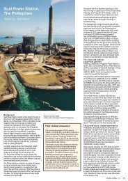
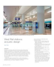
29. The <strong>Aspire</strong> <strong>Tower</strong> and Khalifa Stadium during the Games.<br />
Fire engineering<br />
A highly fire-engineered approach was necessary for the tower’s fire safety design,<br />
making use of its architectural features to achieve the expected level of safety and<br />
at the same time minimize costs. In the absence of specific local codes for high-rise<br />
buildings in <strong>Doha</strong>, this fire strategy was based mainly on the approach described in<br />
various appropriate British Standards, chosen for their good guidance on tall<br />
buildings and provision for fire-fighting activities.<br />
The fundamentals of the escape route design were largely determined by the<br />
cylindrical structural core design: two exits from each storey into opposite sides of<br />
the core, from a racetrack corridor on the hotel levels, served by two separate<br />
stairways in the core. The designed floor-to-floor height allowed the scissor stair<br />
arrangement. The very robust core wall provides a high degree of fire protection,<br />
and pressurization keeps smoke out of the escape stairways.<br />
As the various accommodation sections are spaced up the tower, this<br />
separation between groups of floors enables staged evacuation in the event of fire,<br />
reducing disruption from unwanted fire alarms and making better use of the<br />
available stair capacity.<br />
The automatic sprinkler installation was designed in accordance with NFPA136 ,<br />
for the protection of all areas, including fire hydrant system throughout the building<br />
in accordance with NFPA147 , for a Class I standpipe system. Gaseous flooding<br />
systems were specified for the electrical rooms and data processing rooms.<br />
Analogue addressable, intelligent fire detection systems are networked, together<br />
with “fire survival” bi-directional communications to a master control and monitoring<br />
panel. The fire alarm system operates on a two-stage principle and is linked with a<br />
voice-alarm system consisting of alert and evacuation alarms in public areas.<br />
Emergency lighting is provided along all escape routes and egress points.<br />
Conclusion<br />
All the main structural elements were completed within the 21 months specified for<br />
the tower’s design and construction, enabling it to fulfil its designated function for<br />
the 2006 Asian Games. Work on the interior spaces continued after the conclusion<br />
of the Games, and were completed during the first half of 2007. The <strong>Aspire</strong> <strong>Tower</strong><br />
has proven to be a momentous project, of which the entire concept, design, and<br />
construction team is very proud.<br />
Gregoir Chikaher is a mechanical engineer, and Global<br />
Hotels & Leisure Business Area Leader for <strong>Arup</strong>, based<br />
in the Building London Hotels and Leisure Group. He<br />
was Project Director for the <strong>Aspire</strong> <strong>Tower</strong>.<br />
John Hirst is a structural engineer and a Director of<br />
<strong>Arup</strong> in the Building 6 Group. He was lead structural<br />
engineer for the <strong>Aspire</strong> <strong>Tower</strong>.<br />
Credits<br />
Client/main contractor: Midmac-Six Construct JV<br />
Concept architect: Hadi Simaan Executive architect:<br />
Arep SME, fire, acoustics, lift, and wind engineer:<br />
<strong>Arup</strong> - Andrew Allsop, Chris Armstrong, Darren Barlow,<br />
Christopher Brown, Tony Campbell, Lee Carter, Valerie<br />
Chan, Gregoir Chikaher, Dave Choy, Dean Clabrough,<br />
Paul Cross, Antonio Pimentel da Fonseca, Pat Dallard,<br />
Andrea de Donno, Ian Fellingham, Ian Feltham, Anthony<br />
Ferguson, Martin Finch, Pietro Franconiero, Eiji Fujii,<br />
Neal Gardiner, Alexej Goehring, Steve Harris, Mike<br />
Hastings, Kelvin Hindson, John Hirst, Ed Hoare,<br />
Graham Humphreys, Shaed Jalal, Seb Jouan, Martin<br />
Kirk, Joanne Larmour, Charles Macdonald, Steve<br />
Macklin, Adam Martin, Martin McGrellis, Steve<br />
McKechnie, David Mills, Paul Morrison, Brendon Moss,<br />
Julian Olley, Ender Ozkan, Steven Parker, Navin Peiris,<br />
Daniel Powell, Nihal Rajapakse, Laurence Reed, Ricky<br />
Reynolds, Colin Roberts, Agnes Rothery, Nick Rushton,<br />
Ray Sciortino, Alfonso Senatore, Martin Simpson,<br />
Les Stokes, Joe Sumners, Jens Tandler, Martin<br />
Tarnowski, Richard Terry, Pete Thompson, Camilla<br />
Thomson, Gareth Thyer, James Watts, Ian Vigrass,<br />
Mick White, Michael Willford, Derek Woodcraft, Darren<br />
Woolf, Ray Young Interior designer: Ecart Cladding<br />
mesh contractor: JAP Wind tunnel facility: BMT Fluid<br />
Mechanics. Illustrations: 1, 3, 4, 7, 8, 16, 17, 23, 25-<br />
28 <strong>Arup</strong>; 2, 6 Hadi Simaan; 5, 9-11, 15, 21, 22, 24, 29<br />
Midmax-Six Contract JV; 12-14, 18-20 Nigel Whale.<br />
References<br />
(1) CARFRAE, T et al. Khalifa Stadium, <strong>Doha</strong>, <strong>Qatar</strong>.<br />
The <strong>Arup</strong> Journal, 41(1), pp36-43, 2/2006.<br />
(2) http://eom.springer.de/R/r082500.htm<br />
(3) INTERNATIONAL CODE COUNCIL. Uniform building code<br />
1997. ICC, 1997.<br />
(4) BRITISH STANDARDS INSTITUTION. BS8110.<br />
The structural use of concrete. BSI, 1985 onwards.<br />
(5) BRITISH STANDARDS INSTITUTION. CP3: Chapter V: Part<br />
2. Wind loading of building structures: Part 2. BSI, 1972.<br />
(6) NATIONAL FIRE PROTECTION ASSOCIATION. NFPA13.<br />
Standard for the installation of sprinkler systems. NFPA, nd,<br />
revised bi-annually.<br />
(7) NATIONAL FIRE PROTECTION ASSOCIATION. NFPA14.<br />
Standard for the installation of standpipes and hose systems.<br />
NFPA, nd, revised bi-annually.<br />
The <strong>Arup</strong> Journal 2/2007 13