3 Ngong Ping 360 John Batchelor, Suresh Tank 15 Waste as ... - Arup
3 Ngong Ping 360 John Batchelor, Suresh Tank 15 Waste as ... - Arup
3 Ngong Ping 360 John Batchelor, Suresh Tank 15 Waste as ... - Arup

Create successful ePaper yourself
Turn your PDF publications into a flip-book with our unique Google optimized e-Paper software.
2<br />
The <strong>Arup</strong> Journal 1/2008<br />
Contents<br />
3 <strong>Ngong</strong> <strong>Ping</strong> <strong>360</strong><br />
<strong>John</strong> <strong>Batchelor</strong>, <strong>Suresh</strong> <strong>Tank</strong><br />
<strong>15</strong> <strong>W<strong>as</strong>te</strong> <strong>as</strong> a driver of change<br />
Part 1: The nature of the problem<br />
and why we have it<br />
Rachel Birch<br />
25 Textus<br />
Mark Fletcher, Richard Greer,<br />
Dan Lister, Karen Walters<br />
28 The Hylomorphic Project<br />
Judith Leuppi, Kristina Shea<br />
31 Złote Tar<strong>as</strong>y, Warsaw, Poland<br />
Darren Anderson, Zbigniew Czajewski,<br />
Stuart Clarke, Ian Feltham, Paul Geeson,<br />
Marcin Karczmarczyk, Richard Kent,<br />
David Killion, Zbigniew Kotynia,<br />
Maciej Lewonowski, Robert Lindsay,<br />
Philip Monypenny, Chris Murgatroyd,<br />
<strong>John</strong>ny Ojeil, Raf Orlowski, Andrzej Sitko,<br />
Darren Woolf<br />
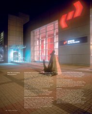
54 MCASD Downtown expansion:<br />
The Joan & Irwin Jacobs Building and<br />
the David C Copley Building<br />
Peter Berry, Jeffrey Huang, Ricardo Pittella<br />
58 Urbanization <strong>as</strong> a driver of change<br />
Susan Thom<strong>as</strong><br />
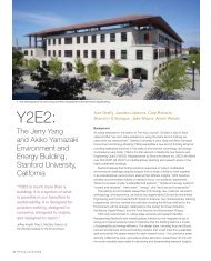
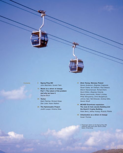
1. P<strong>as</strong>senger cabins on the <strong>Ngong</strong> <strong>Ping</strong> <strong>360</strong><br />
cableway p<strong>as</strong>s each other above Lantau<br />
Island, Hong Kong.
2. The Airport Island angle station (AIAS), leading to Tower 2B.<br />
3. The Tian Tan Buddha, <strong>Ngong</strong> <strong>Ping</strong>.<br />
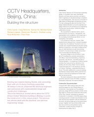
Hong Kong’s latest tourist<br />
attraction is the largest cable car<br />
system of its kind in the world.<br />
<strong>Ngong</strong> <strong>Ping</strong> <strong>360</strong><br />
<strong>John</strong> <strong>Batchelor</strong> <strong>Suresh</strong> <strong>Tank</strong><br />
Introduction<br />
<strong>Ngong</strong> <strong>Ping</strong> <strong>360</strong>, one of Hong Kong’s most challenging and complex tourism<br />
projects, is a cableway linking Tung Chung and <strong>Ngong</strong> <strong>Ping</strong> [pronounced “nong<br />
ping”], on Lantau Island immediately south of Hong Kong International Airport.<br />
Tung Chung is a new town developed in conjunction with the airport, whilst<br />
<strong>Ngong</strong> <strong>Ping</strong> is home to the 34m tall Tian Tan Buddha, the world’s largest outdoor<br />
seated bronze figure, completed in 1993 and weighing over 250 tonnes, and the<br />
nearby Po Lin mon<strong>as</strong>tery. Continuing the theme nearby is <strong>Ngong</strong> <strong>Ping</strong> Village,<br />
with attractions like “Walking with Buddha”, “Monkey’s Tale Theatre”, and the<br />
<strong>Ngong</strong> <strong>Ping</strong> Tea House, <strong>as</strong> well <strong>as</strong> shops, restaurants, and live entertainment.<br />
Totalling 5.7km in length, this bi-cable, circulating, detachable, cable car<br />
system is believed to be the largest of its kind in the world. Each cabin carries<br />
17 p<strong>as</strong>sengers (10 seated and seven standing), and the system h<strong>as</strong> the second<br />
highest transport capacity, with 3500 p<strong>as</strong>sengers per hour each way. It also<br />
achieves the greatest speed yet (7m/sec) in a detachable circulating system,<br />
and h<strong>as</strong> the largest diameter track rope (70mm) for a bi-cable system.<br />
The journey of 20-25 minutes from Tung Chung terminal gives panoramic views<br />
over the North Lantau Country Park, the South China Sea, Hong Kong International<br />
Airport, and surrounding are<strong>as</strong>, and culminates in a breathtaking scenic panorama<br />
<strong>as</strong> it approaches the Tian Tan Buddha and <strong>Ngong</strong> <strong>Ping</strong>.<br />
The <strong>Arup</strong> Journal 1/2008 3
4<br />
Background<br />
<strong>Ngong</strong> <strong>Ping</strong> is an important Hong Kong tourist<br />
attraction. It h<strong>as</strong> around 1M visitors a year, despite<br />
its poor transport connections - the bus journey<br />
takes about an hour from Tung Chung on a narrow,<br />
winding road. Studies were carried out during the<br />
1990s on the development of a cable car link<br />
between the Tung Chung new town and <strong>Ngong</strong><br />
<strong>Ping</strong> <strong>as</strong> part of the then Hong Kong government’s<br />
initiative to develop Lantau <strong>as</strong> a tourism destination.<br />
After a competitive bid process, in July 2002<br />
the MTR Corporation Ltd (MTRCL) and the<br />
government of Hong Kong Special Administrative<br />
Region (HK SAR) entered into a provisional<br />
agreement for the project, by then known <strong>as</strong><br />
Tung Chung Cable Car. During this period the<br />
government enacted the Tung Chung Cable Car<br />
ordinance and the MTRCL carried out, and<br />
obtained approval of, an environmental impact<br />
<strong>as</strong>sessment and a scheme design.<br />
In November 2003, the MTRCL and the HK<br />
SAR signed a project agreement for the cable car.<br />
The franchise commenced on 24 December 2003<br />
and will l<strong>as</strong>t for 30 years, after which the system will<br />
be transferred free to the government for continued<br />
operation <strong>as</strong> a tourist attraction.<br />
Project management<br />
Contract and procurement<br />
With its aim a world-cl<strong>as</strong>s but cost-effective<br />
tourism project, the MTRCL decided on a target<br />
cost contract, with pain share/gain share provisions<br />
within its standard design-and-build contract<br />
format. It adopted a two-stage tender process,<br />
and Maeda Corporation - supported by <strong>Arup</strong> -<br />
w<strong>as</strong> successful in the Stage 1 tender <strong>as</strong>sessment<br />
and w<strong>as</strong> invited to proceed to Stage 2 <strong>as</strong> the<br />
appointed tenderer. A key part of the winning<br />
proposal w<strong>as</strong> its cost-saving alternative design<br />
me<strong>as</strong>ures, several of which were incorporated into<br />
the subsequent target cost model.<br />
The objective of the Stage 2 process w<strong>as</strong> to<br />
develop a scheme/developed design and related<br />
working methods, with a mutually agreed and<br />
realistic target cost for the works, and this duly<br />
enabled the target cost contract to be awarded to<br />
Maeda, supported by <strong>Arup</strong> for engineering design.<br />
25.6m<br />
The <strong>Arup</strong> Journal 1/2008<br />
Tung Chung<br />
terminal<br />
117m<br />
43.2m<br />
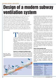
5. Elevation of the cable car system (continues on subsequent pages).<br />
l<br />
Tower 1<br />
37m<br />
k<br />
j<br />
h<br />
n<br />
m<br />
o<br />
i<br />
g<br />
f<br />
4. Route alignment for the cable car system: (a) Tung Chung terminal, (b) Tower 1, (c) Tower 2A,<br />
(d) Airport Island angle station, (e) Tower 2B, (f) Tower 3, (g) Tower 4, (h) Tower 5, (i) Nei Lak<br />
Shan angle station, (j) Tower 6, (k) Tower 7, (l) <strong>Ngong</strong> <strong>Ping</strong> terminal, (m) <strong>Ngong</strong> <strong>Ping</strong> Village,<br />
(n) Tian Tan Buddha, (o) Po Lin mon<strong>as</strong>tery.<br />
The Stage 2 design team, comprising the MTRCL’s design consultant (Aed<strong>as</strong> Ltd<br />
supported by Mott Connell), and its own team members, w<strong>as</strong> b<strong>as</strong>ed in the MTRCL<br />
office, working closely with the appointed tenderer. They were supported by cable<br />
car operator Skyrail-ITM, from Australia, and the ropeway designer Leitner GmbH,<br />
from Austria.<br />
The scope of the building and civil engineering works contract required Maeda<br />
and <strong>Arup</strong> to design tower foundations and pilecaps <strong>as</strong> well <strong>as</strong> provide input to the<br />
value engineering. Leitner GmbH w<strong>as</strong> responsible for designing the ropeway and<br />
steel towers under a separate, interfacing contract. A target cost for the works w<strong>as</strong><br />
agreed at the end of Stage 2 and Maeda w<strong>as</strong> awarded the contract to proceed<br />
with Stage 3 - the detail design and construction. Within this, <strong>Arup</strong> and Aed<strong>as</strong>, <strong>as</strong><br />
project architect, carried out the detailed design of the works, with <strong>Arup</strong> providing<br />
civil, geotechnical, SMEP, and fire services design of the following major elements:<br />
• Tung Chung terminal building<br />
• two turning angle stations - Airport Island and Nei Lak Shan<br />
• <strong>Ngong</strong> <strong>Ping</strong> terminal building<br />
• the <strong>Ngong</strong> <strong>Ping</strong> theme village and its <strong>as</strong>sociated attractions<br />
• diversion of 390m of <strong>Ngong</strong> <strong>Ping</strong> stream, constructed from gabions<br />
d<br />
c<br />
e<br />
355m<br />
b<br />
a
Tower 2A<br />
21m<br />
• foundation design of eight towers<br />
• slope stabilization and mitigation me<strong>as</strong>ures for towers and angle stations<br />
• approximately 6km of rescue trail along the cable car alignment<br />
• infr<strong>as</strong>tructure <strong>as</strong>sociated with the terminal buildings, the theme village, and the<br />
angle stations.<br />
A site team from the MTRCL and Maeda w<strong>as</strong> established in shared project offices<br />
in Tung Chung and <strong>Ngong</strong> <strong>Ping</strong>, with the aim of providing effective everyday<br />
communications and quick joint decisions. At peak, the <strong>Arup</strong> team totalled around<br />
50 engineering design staff in Hong Kong, with support from the <strong>Arup</strong> Shenzhen<br />
and Manila offices to meet multiple deadlines for design submissions.<br />
Building approvals<br />
All private building projects in Hong Kong are strictly controlled from design through<br />
to occupation by the Government Building Authority via its Buildings Department<br />
(BD). As <strong>Ngong</strong> <strong>Ping</strong> <strong>360</strong> is a private initiative operated by a non-government<br />
company, the project had to be carried out under the Buildings Ordinance.<br />
Full structural submissions including foundations and their geotechnical input<br />
were submitted to the BD for formal approval and consent, <strong>as</strong> until consent is<br />
issued no construction may proceed for that particular element of the work. Normal<br />
approval processing is carried out within a 60 calendar day window, followed by a<br />
28-day period for formal consent to be issued. The BD insisted that each station<br />
and tower – a total of 13 sites - be treated <strong>as</strong> a separate project from the point of<br />
view of submissions, which added significant challenges of complexity.<br />
Responsibility for submissions, gaining approvals, consents, and subsequent<br />
safe execution within the strict controls of the Buildings Ordinance lies with<br />
professionally qualified individuals appointed by the project promoter. These<br />
individuals have a duty to see that the works are designed and constructed to the<br />
Ordinance. Overall responsibility lies with the authorized person (AP) - usually an<br />
architect - with the structural and geotechnical issues taken by a registered<br />
structural engineer (RSE) and registered geotechnical engineer (RGE). For <strong>Ngong</strong><br />
<strong>Ping</strong> <strong>360</strong>, these latter individuals were <strong>Arup</strong> staff, with Aed<strong>as</strong> providing the AP role.<br />
At the commencement of the project, the MTRCL initiated and chaired weekly<br />
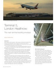
6. The dynamic roof structure of the Tung Chung terminal building.<br />
52.5 m<br />
52m<br />
Airport Island angle station<br />
40.2m<br />
88m<br />
56.7m<br />
Tower 2B<br />
50m<br />
meetings between <strong>Arup</strong>, Aed<strong>as</strong>, and Maeda to<br />
monitor a programme of BD submissions, reviewing<br />
conditions imposed by BD during the processing,<br />
and monitoring the programme tightly due to the<br />
unprecedented number of submissions (over 200)<br />
required to cover the engineering <strong>as</strong>pects of the<br />
work. <strong>Arup</strong>’s work covered the building structures<br />
and tower foundations, but excluded the towers<br />
themselves and other secondary support structures<br />
covered by separate RSEs in other companies.<br />
Partnering<br />
The concept of partnering w<strong>as</strong> introduced at the<br />
outset. Several partnering and value management<br />
workshops, facilitated by an external consultant,<br />
were held for the project team including top<br />
management and front end site staff.<br />
Regular monthly partnering meetings were also<br />
held on site to monitor the objectives in the project<br />
charter signed by all involved. This approach proved<br />
successful, with all parties working together to<br />
achieve common goals and creating a barrier-free<br />
and harmonious working relationship.<br />
The cost challenges, and the complex approvals<br />
process which impacted the design costs, also<br />
tested the partnering concept, since <strong>Arup</strong> had<br />
committed to a fixed lump sum fee in advance of<br />
the BD requirements being known. However, mutual<br />
commitment to partnering by all parties enabled<br />
these challenges to be resolved without breakdown<br />
of relationships or retreat to contractual positions<br />
that would have delayed the project.<br />
The <strong>Arup</strong> Journal 1/2008 5
6<br />
7. Tung Chung terminal building and Tower 1.<br />
8. Anchor drum and cabin storage at Tung Chung terminal.<br />
The <strong>Arup</strong> Journal 1/2008<br />
Tung Chung terminal, elevated walkway, and footbridge<br />
The Tung Chung terminal (Fig 7) forms the gateway to the cable car system and<br />
this is reflected in the design, with its dynamic steel roof structure (Fig 6) and its<br />
range of architectural finishes.<br />
The main roof is split into three sections with a standing seam metal finish to the<br />
top side with concealed gutters and edge profiles. The roof structure comprises<br />
several monopitch frames with varied geometry to achieve the dynamic curved roof<br />
profile whilst keeping the fabrication and construction simple. All the steel members<br />
are straight but angled in varying directions b<strong>as</strong>ed on geometry developed by <strong>Arup</strong><br />
from Aed<strong>as</strong>’ original design intent, working interactively with the project architects.<br />
The upper (platform) level is mainly for the p<strong>as</strong>sengers to board and alight, and<br />
contains provisions for ticketing, queuing, and retail. All 112 cable car cabins are<br />
stored at night on the first floor level, below the platform level. The two track ropes<br />
supporting the system’s vertical loads, one for each direction of travel, are diverted<br />
from the main vertical support through an opening in the platform slab and down to<br />
the anchorage point. The anchor drum, approximately 4.5m in diameter (Fig 8),<br />
is at this level and extends down to the pile cap. A mezzanine at first floor provides<br />
additional retail storage. Electrical and mechanical plant is mainly at the ground<br />
floor level, though it also occupies some additional first floor are<strong>as</strong>.<br />
The main building structure is of reinforced concrete, supporting the roof above<br />
at platform level. Bored piles founded in rock carry the structure. An elevated<br />
walkway and a footbridge with stairs and escalators connect cable car p<strong>as</strong>sengers<br />
to Tung Chung MTR station (another <strong>Arup</strong> project 1 ). Coach parking and bus and<br />
taxi interchange are also nearby.<br />
Airport Island angle station (AIAS)<br />
General<br />
The AIAS site is in the lower portion of a cut slope adjacent to the junction of Chek<br />
Lap Kok South Road and Scenic Road, roughly 2.5km from the airport terminal<br />
building and some 600m from the main cable car terminal building in Tung Chung.<br />
It provides a turning point for the cable cars towards <strong>Ngong</strong> <strong>Ping</strong>, and h<strong>as</strong> six levels<br />
- five of accommodation plus a platform at the top. Matching that of the Tung<br />
Chung terminal building, the roof is a monopitched standing seam metal roof<br />
supported by a slender steel frame with concealed gutters and edge profiles.<br />
The station houses the main drive units for two sections of the system:<br />
the 600m back to the Tung Chung terminal building via Towers 2A and 1; and also<br />
the longer uphill section, with a rise in elevation of 550m and a distance of<br />
approximately 3.5km to the Nei Lak Shan angle station (NLSAS) via Towers 2B, 3,<br />
4, and 5. The main control room for surveillance of the system is also here.<br />
A 6m wide access road connecting to Scenic Road facilitates future<br />
maintenance access, heavy equipment and material delivery,<br />
and possible use by emergency vehicles.<br />
<strong>15</strong>12m
9. Structural support at the AIAS for cable catenaries leading<br />
to Tower 3 and on to Nei Lak Shan angle station (NLSAS).<br />
Structure<br />
The top level of the AIAS reinforced concrete<br />
superstructure is a platform 25m above ground level<br />
(Fig 9), comprising two 40m long and 14m wide<br />
arms projecting from the central core at 120°<br />
relative to one another (Fig 10), each supported by<br />
a single row of reinforced concrete pillars down to<br />
bedrock. These arms support the structure for the<br />
separate systems of cables that serve the lengths<br />
from the Tung Chung terminal building and on<br />
towards the NLSAS. For each, a single row of<br />
reinforced concrete piers above platform level<br />
supports the main track and haul ropes and the<br />
<strong>as</strong>sociated cable car equipment and maintenance<br />
walkways. At the end of each platform arm, a single<br />
pier forms the main vertical support for<br />
the cable catenaries.<br />
10. 120° angle between the AIAS arms leading to Tung Chung terminal building and to the NLSAS.<br />
The foundations are a combination of pad foundations on grade II/III rock for<br />
the columns that support the AIAS structure, and a raft foundation and pre-bored<br />
rock-socketed H-piles under the central core, providing overall stability under lateral<br />
loads. Rock joint mapping, boulder surveys, and slope stability <strong>as</strong>sessment were<br />
carried out to justify the proposed foundation and rock slopes.<br />
The haul rope provides traction for the cable car system but does not support<br />
the weight of the cars themselves. It runs along either side of the central line of<br />
piers above the level 6 platform and is driven by a bull wheel on the pier closest to<br />
the central core. The bull wheel is connected by a drive shaft to a motor in the<br />
level 5 plantroom below.<br />
Two track ropes support the system’s vertical loads, one for each direction of<br />
travel. They are diverted from the main vertical support, down below the level 6<br />
platform at an anchorage point within the level 5 plantrooms. The maximum design<br />
load on a single track rope, generated by the weight of the cable car system <strong>as</strong><br />
well <strong>as</strong> other dynamic effects, is over 200 tonnes (2000kN of force). The combined<br />
effects of these loads from each side of the station, together with their 25m height<br />
above foundation level, generate the large overturning forces that in turn controlled<br />
the foundation design and stiffness of the superstructure. These permanent<br />
overturning forces are resisted by 500mm thick reinforced concrete core walls that<br />
spring from a stepped raft foundation, c<strong>as</strong>t onto the cut rock slope and anchored<br />
by seven pre-bored rock-socketed H-piles.<br />
The ropeway designer produced a simplified envelope of design forces for each<br />
anchorage location for the civil works design, characterized by maximum and<br />
minimum loads for each location and loadc<strong>as</strong>e type. Cable loads for dead, live and<br />
wind loadc<strong>as</strong>es were provided for both an operational c<strong>as</strong>e, with a limited design<br />
wind speed of 135km/hr, and an out-of-operation c<strong>as</strong>e, subject to full<br />
typhoon wind loads. The loads were defined by moments and<br />
forces in all three global axis directions and resulted in<br />
over 100 design combinations that were<br />
themselves enveloped to complete<br />
the design of the foundations<br />
and superstructure.<br />
312.6m<br />
Tower 3<br />
17m<br />
The <strong>Arup</strong> Journal 1/2008 7
8<br />
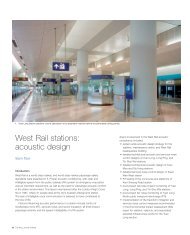
11. Nei Lak Shan angle station and Tower 4 slope reinstated<br />
after completion of stabilization works.<br />
12. Geological model showing raking piles socketed in rock<br />
(blue) together with boreholes and structure above.<br />
The <strong>Arup</strong> Journal 1/2008<br />
Nei Lak Shan angle station (NLSAS)<br />
General<br />
This building w<strong>as</strong> sited on a rounded hilltop (Fig 11) with difficult access upslope<br />
from Tower 5 in Lantau North Country Park. It provides the turning point for the<br />
change of direction of the cable car towards <strong>Ngong</strong> <strong>Ping</strong>. As at AIAS, the cable<br />
cars detach from the rope and move at reduced speed along the station, so <strong>as</strong> to<br />
maintain riding comfort for the p<strong>as</strong>sengers before attaching back to the rope.<br />
The station comprises a lower ground level (b<strong>as</strong>ement) and a ground (platform)<br />
level. The roof superstructure is monopitch steel frames and roof finishes similar to<br />
that of AIAS, with concealed gutters and edge profiles.<br />
Foundations<br />
The foundations are simple pads and strip footings for the single-storey electrical<br />
and mechanical services buildings, and pilecaps and raking minipiles over the<br />
central structure supporting the cable car anchor drums and reinforced concrete<br />
columns. The minipiles were proposed due to the difficult site access (achieved by<br />
helicopters) and to minimize environmental impact. They rake in two directions<br />
(Fig 12) to resist the vertical and lateral loads - their orientation, number, and<br />
lengths being established after rigorous analysis that took into account several<br />
combinations of cable car loadings provided by the ropeway designer.<br />
1063m<br />
A 3-D model of the ground conditions w<strong>as</strong> created to <strong>as</strong>sess whether any adverse<br />
geological features were present that could affect the size and shape of the rock<br />
and soil cones <strong>as</strong>sumed in the tension capacity calculation, <strong>as</strong> well <strong>as</strong> the stability<br />
of any nearby slopes. The model w<strong>as</strong> b<strong>as</strong>ed on the findings of all previous and new<br />
ground investigations, <strong>as</strong> well <strong>as</strong> geological mapping and a desk study review of<br />
geological information of the area.<br />
The geological model did not identify any significant shearing or faulting running<br />
through the area of the foundations, and confirmed that no such adverse geological<br />
features would affect their overall stability or that of any adjacent slopes. It also<br />
confirmed the choice of socket length for each minipile under the structure.<br />
Structure<br />
Open cut staged excavations were undertaken to enable construction of the<br />
foundations, the excavation plans being prepared after discussion with the<br />
construction team, so <strong>as</strong> to suit the preferred construction method. Due to the<br />
site’s remoteness, every effort w<strong>as</strong> made to minimize the volume of excavated<br />
material that had to be removed.<br />
The foundations for the single-storey E & M services buildings were raised,<br />
both to minimize the volume of excavation and limit bearing pressures to less than<br />
100kPa. This w<strong>as</strong> to avoid regulatory requirements for plate load tests, which would<br />
have been very expensive and difficult to carry out on this remote site.<br />
The top level of the NLSAS reinforced superstructure forms the platform. It is<br />
some 5.5m above the pilecap formation level, and comprises 40m and 35m long<br />
sections of platforms from the centre, at 160° relative to each other and supported<br />
by a single row of reinforced concrete pillars down to the pilecaps. These columns<br />
support the main track, the haul ropes, and the <strong>as</strong>sociated equipment for the<br />
cable car systems between the NLSAS and AIAS, and between the NLSAS and<br />
<strong>Ngong</strong> <strong>Ping</strong> terminal.
13. Roof structure at angle stations.<br />
For the roof structure, three alternative schemes were compared to identify the<br />
most economic solution, <strong>as</strong> opposed to the large portal frame structures originally<br />
proposed, which formed the b<strong>as</strong>is of the target cost contract during Stage 2 for<br />
both the AIAS and the NLSAS. The final scheme adopted is a trussed frame<br />
(Fig 13), which simplified connection details and only amounted to about half the<br />
steelwork weight of the Stage 2 scheme. Columns and bracing along the central<br />
gridline were limited to locations agreed with the ropeway designer.<br />
Towers<br />
General<br />
There are eight towers in all, five of them in the country park (Towers 3, 4, 5, 6,<br />
and 7). The building and civil engineering contract 5201 included construction of<br />
the foundations and pilecaps within <strong>Arup</strong>’s scope of works. <strong>Arup</strong> also took over<br />
all natural terrain hazard <strong>as</strong>sessment and mitigation works <strong>as</strong>sociated with the<br />
foundation design in the country park, including identification of hazards, boulder<br />
surveys, rock joint mapping, design of mitigation me<strong>as</strong>ures like soil nailing and<br />
boulder stabilization, and regulatory approval processes.<br />
Foundations<br />
Vertical pre-bored H-piles were adopted for Towers 1 and 2B, and a combination<br />
of vertical and raking minipiles for Towers 2A and 3-7, with rock sockets to resist<br />
tension and compression. Minipiles were the preferred option for works in the<br />
country park <strong>as</strong> they could be installed with small rigs.<br />
A typical tower foundation comprises a series of vertical and raking minipiles<br />
in two directions under a single pilecap supporting each tower leg. The ropeway<br />
designer supplied data on the most critical loads for each support, including the<br />
effects of dead load, imposed loads, wind, and earthquake loads (<strong>as</strong> required by<br />
MTRCL) from both the tower steel superstructure and the cable car system.<br />
The maximum and minimum loads in each of the three axes, together with<br />
co-existing loads, were analyzed to give all possible load combinations from the<br />
superstructure and the cable car above. Hundreds had to be <strong>as</strong>sessed so <strong>as</strong> to<br />
determine the loads in the piles and for the design of the pilecaps.<br />
14. Tower 2B.<br />
492.0m<br />
Tower 4<br />
49m<br />
Table 1: Tower and station distances<br />
Tung Chung terminal<br />
Tower 1<br />
Tower 2A<br />
Airport Island angle station<br />
Tower 2B<br />
Tower 3<br />
Tower 4<br />
Tower 5<br />
Nei Lak Shan angle station<br />
Tower 6<br />
Tower 7<br />
<strong>Ngong</strong> <strong>Ping</strong> terminal<br />
Table 2: Tower heights<br />
Horizontal<br />
distance<br />
Tower 1 37 12 2.5<br />
Tower 2A 21 7 2.5<br />
Tower 2B 50 16 2.5<br />
Tower 3 17 7 7<br />
Tower 4 49 16 2.5<br />
Tower 5 44 13 2.5<br />
Tower 6 27 9 2.5<br />
Tower 7 46 16 4<br />
* Below tower head<br />
Tower height<br />
in the axis<br />
Inclined<br />
distance<br />
1 16 117<br />
355 355<br />
51 52<br />
86 88<br />
1490 <strong>15</strong>12<br />
1048 1063<br />
83 3 838<br />
29 30<br />
161 161<br />
96 9 974<br />
38 6 388<br />
Tower width<br />
at b<strong>as</strong>e<br />
Tower width<br />
at top*<br />
The <strong>Arup</strong> Journal 1/2008 9
10<br />
The design of Tower 7 proved the greatest<br />
challenge to the project team in devising a<br />
solution, taking it through the BD approvals<br />
process, and obtaining consents for<br />
construction over a fault zone.<br />
B<strong>as</strong>ed on the ground investigation provided<br />
by MTRCL (three boreholes and trial pits<br />
near the Tower 7 location), <strong>Arup</strong>’s foundation<br />
design comprised vertical and raking<br />
minipiles socketed in rock a few metres<br />
below ground level. This w<strong>as</strong> approved by<br />
the BD and consent w<strong>as</strong> granted.<br />
After BD approval and consent of the<br />
foundation pre-drilling, however, some of<br />
the early pre-drill holes revealed a rockhead<br />
level significantly lower than that anticipated<br />
from the original ground investigation holes.<br />
A total of 29 more holes were then drilled<br />
on a plan area of 45m x 45m to provide<br />
additional information for reviewing the<br />
ground conditions at the tower location.<br />
A 3-D geological model for the tower w<strong>as</strong><br />
developed using data from all the boreholes<br />
and drill holes. The depth to the grade III<br />
rockhead w<strong>as</strong> found to be extremely variable<br />
(7.6m to more than 60m), which w<strong>as</strong><br />
interpreted <strong>as</strong> being due to the presence of<br />
a fault zone at the tower.<br />
The <strong>Arup</strong> Journal 1/2008<br />
<strong>15</strong>. Tower 2A.<br />
Tower 7:<br />
foundation design<br />
17. Geological model showing transfer<br />
beams spanning across the fault with<br />
minipiles (red) founded in grade IV or<br />
better rock.<br />
16. Tower 4.<br />
838m<br />
18. The completed Tower 7 showing the<br />
extent of slope stabilization, and the<br />
tower plinths.<br />
Relocating it w<strong>as</strong> not an option, <strong>as</strong> this<br />
would have had huge impact on cost and<br />
programme: the changed alignment would<br />
have meant the redesign by the ropeway<br />
designer of the towers, a requirement for<br />
additional land for the tower, further ground<br />
investigation and submission to the BD, a<br />
redesign of the tower foundations and<br />
stabilization me<strong>as</strong>ures, and further approvals.<br />
A raft spanning across the fault w<strong>as</strong> also<br />
considered, with minipiles beneath it for<br />
stability. However, this option w<strong>as</strong> ruled out<br />
due to the requirement for a large volume of<br />
concrete in a remote area with difficult<br />
access, the extra cost and programme<br />
implications, and impact on the stability of<br />
the existing slope due to the additional load<br />
of the raft.<br />
The solution adopted, therefore, w<strong>as</strong> a fourbeam<br />
transfer structure spanning across the<br />
fault zone and supporting the four plinths of<br />
the steel tower (Fig 17). The transfer beams<br />
are supported on raking minipiles (18.4° to<br />
the vertical) and carefully located away from<br />
the fault zone in grade IV/III or better rock.<br />
With a lot of effort from the design and<br />
construction team and the MTRCL, the<br />
geological model w<strong>as</strong> agreed with the<br />
appropriate approval departments.<br />
19. Towers, the rescue trail and Nei Lak Shan angle station.<br />
20. Tower 3.
583.5m<br />
Tower 5<br />
44m<br />
Nei Lak Shan angle station<br />
30m 161m<br />
<strong>Ngong</strong> <strong>Ping</strong> terminal<br />
575.2m<br />
Prior to any construction works in the <strong>Ngong</strong> <strong>Ping</strong><br />
area, the <strong>Ngong</strong> <strong>Ping</strong> stream, which flowed directly<br />
through the site, had to be diverted to run parallel<br />
to the site’s northern boundary and rejoin the<br />
existing watercourse immediately downstream of<br />
the terminal building.<br />
Approximately 390m of banks for the diverted<br />
stream were constructed of rectangular galvanized<br />
steel mesh gabion b<strong>as</strong>kets, filled with crushed rocks<br />
excavated on site (Fig 21). Gabion mattresses for<br />
the stream bed were proposed by the Stage 2<br />
designers, but were replaced by natural crushed<br />
rocks excavated on site to enhance the<br />
environmental and ecological value of the diverted<br />
stream. Additional calculations by <strong>Arup</strong> showed that<br />
the change to the stream bed lining would have no<br />
impact on the stream’s hydraulics. Detail design,<br />
government approval, and construction of the<br />
stream were all completed within five months of<br />
award of contract and before the 2004 rainy se<strong>as</strong>on<br />
commenced (Fig 22).<br />
21. Stream diversion under construction, showing<br />
gabion b<strong>as</strong>kets.<br />
22. <strong>Ngong</strong> <strong>Ping</strong> stream diverted.<br />
Tower 6<br />
27m<br />
585.0m<br />
23. <strong>Ngong</strong> <strong>Ping</strong> Village: the terminal building is on the right, with <strong>Ngong</strong> <strong>Ping</strong> sewerage treatment<br />
works (another <strong>Arup</strong> project) in the background.<br />
The terminal forms the start of the <strong>Ngong</strong> <strong>Ping</strong> cultural experience, and this is<br />
reflected in theming to complement the theme village itself. The superstructure of<br />
the latter’s buildings are in concrete with Chinese roof tiles, except for the main<br />
terminal building roof which is of structural steel with a standing seam metal finish.<br />
The terminal building frame is in reinforced concrete with one b<strong>as</strong>ement level.<br />
The terminal building accommodates the ticketing, pre-ride queuing and<br />
<strong>as</strong>sociated retail, covered walkway, plant, administration, and maintenance are<strong>as</strong>.<br />
Emergency vehicle access is provided around the building with the main utilities<br />
laid under footpaths.<br />
<strong>Ngong</strong> <strong>Ping</strong> theme village<br />
The theme village (Fig 23) h<strong>as</strong> three are<strong>as</strong> of one and two-storey buildings with a<br />
traditional regional Chinese character. Maeda and <strong>Arup</strong> opted to replace the steel<br />
frames proposed by the Stage 2 designer with concrete frames to reduce cost and<br />
save time. Most of the design and drawing production for the village w<strong>as</strong> carried<br />
out in <strong>Arup</strong>’s Shenzhen and Manila offices and checked by the Hong Kong office<br />
before being submitted to the BD for approval.<br />
The <strong>Arup</strong> Journal 1/2008 11
12<br />
25. Detail of rescue trail timber construction.<br />
The <strong>Arup</strong> Journal 1/2008<br />
26. A Kamov helicopter<br />
approaching Tower<br />
3 (Hong Kong<br />
International Airport<br />
on Chek Lap Kok –<br />
also an <strong>Arup</strong><br />
project - is in the<br />
background).<br />
24. One of the six mules used for transporting loads up to<br />
120kg on narrow trails in the country park.<br />
974m<br />
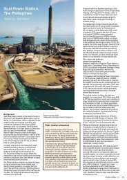
Environmental considerations<br />
The project team put great emph<strong>as</strong>is on environmental considerations. The route<br />
alignment and the type of cable car system were both selected to minimize the<br />
number of towers required in the country park. Ecological surveys were carried out<br />
by others and protected species from the tower sites were relocated.<br />
Rather than build a haul road, helicopters and mules were used to transport<br />
materials. Six mules were specially brought from Alberta, Canada, to transport<br />
water, fuel, and construction materials on a narrow steep trail to NLSAS and Towers<br />
6 and 7. The mules proved able to carry up to 120kg loads, and worked seven<br />
hours a day, six days a week, for 14 months (Fig 24).<br />
Due to the nature (and weight) of <strong>Ngong</strong> <strong>Ping</strong> <strong>360</strong>’s construction materials,<br />
two types of helicopter were used, the French-built Lama and the Russian Kamov.<br />
The Lam<strong>as</strong> were used to transport mainly concrete and reinforcing bars to remote<br />
sites and could carry loads of up to one tonne. During peak periods, they operated<br />
up to seven and eight hours a day transporting materials to the remote tower sites<br />
in North Lantau Country Park. The Kamov (Fig 26) w<strong>as</strong> brought to Hong Kong<br />
specifically for the <strong>Ngong</strong> <strong>Ping</strong> <strong>360</strong> project and to transport loads of up to 4.5<br />
tonnes; it w<strong>as</strong> used to move the bulkier construction materials, including the<br />
tower “heads”, into remote sites.<br />
The rescue trail<br />
A rescue trail, approximately 6km in length, runs generally along the cable car<br />
alignment, for use in the event of emergency evacuation from one of the cabins.<br />
The trail is constructed in difficult terrain, using timber (Fig 25) or natural stones.<br />
Close co-ordination with Maeda enabled a design to suit the construction<br />
constraints and with minimum impact on the environment of the country park.<br />
Fire engineering<br />
A drencher system between the two levels of each terminal building would normally<br />
be necessary to divide the large single compartment into two while also permitting<br />
cable car movement between the levels through a maintenance stair opening.<br />
This, however, would have required very large water tanks, with additional cost and<br />
space requirements, and would have impacted on the operation of the cable car.<br />
<strong>Arup</strong> provided a performance-b<strong>as</strong>ed fire engineering approach to justify the<br />
deletion of this drencher system. A design fire w<strong>as</strong> established to demonstrate<br />
whether there would be any smoke movement from level 1 to level 2 through the<br />
maintenance stair opening. The temperature and visibility of smoke spill to level 2<br />
w<strong>as</strong> also calculated. To limit the smoke spread from the lower level to the upper,<br />
a high level downstand around the lower floor opening w<strong>as</strong> required, and it w<strong>as</strong><br />
also demonstrated that the downstand can prevent smoke spilling to the high level,<br />
using existing ventilation louvres for smoke outlets.
27. <strong>Arup</strong> <strong>as</strong>sessed materials for glazing the cable car cabins.<br />
Risk <strong>as</strong>sessment<br />
Tower 7<br />
46m<br />
483.0m<br />
MTRCL also appointed <strong>Arup</strong> to <strong>as</strong>sess the<br />
preferred materials for glazing the cable car cabins<br />
(Fig 27). These included polymethyl methacrylate<br />
(PMMA), polyethylene tetrephthalate copolymer<br />
(PETG), and polycarbonate (PC). An <strong>as</strong>sessment of<br />
the implications of these products from the fire<br />
hazard point of view w<strong>as</strong> required for MTRCL to<br />
come to a decision with the cabin manufacturers,<br />
who preferred a more expensive material.<br />
<strong>Arup</strong>’s fire hazard <strong>as</strong>sessment of these glazing<br />
materials included identification and <strong>as</strong>sessing the<br />
likelihood of potential ignition, fire scenarios during<br />
operation, related combustion behaviour and hazard<br />
levels, and a literature review of their use on similar<br />
projects. B<strong>as</strong>ed on the risk <strong>as</strong>sessment, MTRCL<br />
w<strong>as</strong> able to select the appropriate material that w<strong>as</strong><br />
also acceptable to the cabin manufacturers.<br />
Value engineering<br />
During Stage 2, <strong>Arup</strong> and Maeda proposed several<br />
value engineering initiatives. Once agreed with<br />
MTRCL, these were implemented and factored into<br />
the gainshare/painshare equation agreed between<br />
MTRCL and Maeda.<br />
At the Tung Chung terminal, the main structural<br />
frames were altered to use edge cantilevers for<br />
structural efficiency, and to resolve headroom<br />
problems. The roof geometry w<strong>as</strong> developed with<br />
straight members and the elimination of purlins for<br />
simplicity of fabrication, in spite of the complex<br />
roof shape (Fig 29).<br />
Foundation savings in the detailed design of the<br />
piles were achieved, but the more radical alternative<br />
of a raft instead of bored piles, which would have<br />
saved around 20% of the building cost with<br />
appropriate detailing, w<strong>as</strong> not adopted due to<br />
MTRCL’s concerns over the uncertain fill properties<br />
in the area.<br />
28. Computational evacuation software w<strong>as</strong> used to address<br />
the means of escape provision by calculating total<br />
evacuation time. This showed the risk of exposure to<br />
fire and smoke to be low, <strong>as</strong> the total evacuation time is<br />
less than five minutes.<br />
388m<br />
<strong>Ngong</strong> <strong>Ping</strong><br />
terminal<br />
29. Value engineering at Tung Chung terminal: the roof geometry w<strong>as</strong> developed with straight<br />
members and elimination of purlins for simplicity of fabrication, in spite of the complex shape.<br />
As already noted, the application of <strong>Arup</strong>’s fire engineering skills resulted in the<br />
deletion of a large drencher tank and system, whilst the foundation solutions for<br />
the AIAS achieved reduced pile quantities following the critical review by <strong>Arup</strong> of<br />
the piling design.<br />
At the two angle stations, <strong>Arup</strong> achieved reduced steel roof weights of around<br />
50% compared to the target cost figures by using more structurally efficient trussed<br />
frames, which also simplified the lifting problems for those stations in the country<br />
park are<strong>as</strong>. In addition, the minipile sizes were reduced and the excavations<br />
minimized by raising the foundation levels, thus reducing the amount of material to<br />
be disposed of by helicopter or mule.<br />
At the <strong>Ngong</strong> <strong>Ping</strong> terminal and theme village, steel frames were generally<br />
changed to concrete frames, and foundations reduced in size <strong>as</strong> well. Again at the<br />
theme village, the stream diversion gabion layout w<strong>as</strong> reduced to take advantage of<br />
existing rock outcrops found during excavation. Taking into account the approvals<br />
timing and design change costs, each works proposal w<strong>as</strong> evaluated on its merits<br />
and agreed with MTRCL before implementation within the target cost contract.<br />
The benefits of the target cost approach were clear from the alignment of all<br />
parties’ mutual interests towards seeking the most cost-effective solution overall for<br />
the project, using planned and agreed redesign, with extra design costs, to yield<br />
larger savings throughout construction.<br />
The <strong>Arup</strong> Journal 1/2008 13<br />
444.0m
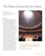
30. <strong>Ngong</strong> <strong>Ping</strong> Village.<br />
Conclusion<br />
<strong>Ngong</strong> <strong>Ping</strong> <strong>360</strong> w<strong>as</strong> a challenging project that required, and received, dedication<br />
from the design team. As noted previously, this included staff not only from <strong>Arup</strong>’s<br />
Hong Kong office, but from the offices in Shenzhen and Manila <strong>as</strong> well. As far <strong>as</strong><br />
the overall design and construction were concerned, the target cost contract<br />
environment worked well to align the interests of Maeda and <strong>Arup</strong> with the MTRCL.<br />
The partnering process enabled all parties to take a joint view of whether design<br />
changes would add value to the project, in the light of ground conditions uncovered<br />
in the field and other issues, such <strong>as</strong> timing and approvals, that impacted the<br />
design and construction.<br />
<strong>Ngong</strong> <strong>Ping</strong> <strong>360</strong> opened on 18 September 2006, but the detachment and fall of<br />
one of the cars during a night time emergency drill on 11 June 2007 – fortunately<br />
without injury or loss of life - caused the system to be shut down while the<br />
accident w<strong>as</strong> investigated. It reopened to the public on 31 December 2007.<br />
As for the public response to this new tourism highlight for Hong Kong, the<br />
government’s initial study predicted 1.5M visitors in the first year of its opening but<br />
on 9 March 2007, less than six months after opening, <strong>Ngong</strong> <strong>Ping</strong> <strong>360</strong> w<strong>as</strong><br />
traversed by its millionth p<strong>as</strong>senger.<br />
31. Cable car approaching <strong>Ngong</strong> <strong>Ping</strong>, showing the Tian Tan Buddha, Tower 7 and the rescue<br />
trail, with the theme village in the background.<br />
14 The <strong>Arup</strong> Journal 1/2008<br />
<strong>John</strong> <strong>Batchelor</strong> is a Director of <strong>Arup</strong> in the<br />
Infr<strong>as</strong>tructure London Group. He w<strong>as</strong> Project Director<br />
for <strong>Ngong</strong> <strong>Ping</strong> <strong>360</strong>.<br />
<strong>Suresh</strong> <strong>Tank</strong> is an Associate of <strong>Arup</strong> at the UK<br />
Midlands Campus. He w<strong>as</strong> Project Manager for<br />
<strong>Ngong</strong> <strong>Ping</strong> <strong>360</strong>.<br />
Credits<br />
Client and design/build contractor: Maeda<br />
Corporation Promoter: MTR Corporation Ltd Hong<br />
Kong Architect: Aed<strong>as</strong> Ltd Civil, SMEP,<br />
geotechnical, and fire engineer: <strong>Arup</strong> – Roger Alley,<br />
<strong>John</strong> <strong>Batchelor</strong>, Arnel Bautista, Ambrose Chan,<br />
Kenneth Chan, Man-Lung Chan, Paul Chan, Spencer<br />
Chan, Henry Cheng, Calvin Cheung, Cici Cheung,<br />
Hung-Cho Cheung, Robot Chiang, Kenneth Chiu,<br />
Joanne Choi, Stephen Chow, Sidney Chu, Stuart<br />
Cowan, Angus Fong, Sandy Fong, Wendy Fong,<br />
Matthew Free, Jim Haley, <strong>John</strong>y Ho, Stephen Hope,<br />
Ji-Guang Kuang, Oi-Yung Kwan, Nelson Kwong, David<br />
Lai, Vivian Lai, Ernest Lam, Maggie Lam, Eric Lau,<br />
Catherine Leung, Ryan Leung, Steve Leung, Vincent Li,<br />
Patrick Lit, Andy Liu, Darwin Lo, Rock Lo, Martino Mak,<br />
Wilson Mak, Jack Pappin, Nelson Pong, Lioni Ramos,<br />
Grant Robertson, Richard Scott, Kin-Piu Shum, Edith<br />
So, David Song, Timothy Suen, Alan Tam, Christine<br />
Tam, <strong>Suresh</strong> <strong>Tank</strong>, Wai-Shing Tang, Kwok-Kei Tse,<br />
Evan Tsui, David Vesey, Colin Wade, Mark Wallace,<br />
Hou-Ju Wang, Kelvin Wong, Louis Wong, Stella Wong,<br />
Eric Wu, Thom<strong>as</strong> Yeung, Xue-Ning Zhang, Jeanne<br />
Zhao, Longde Zhao Ropeway designer: Leitner<br />
GmBH Operator: Skyrail-ITM Specialist contractors –<br />
Minipiling: Simon & Sons Bored piling: Bachy<br />
Soletanche Roof steelwork: Kepple Cladding: Craft<br />
Mechanical and electrical: Kinden Landscape: Tarzan<br />
Specialist attractions – Client: Dedica Group<br />
Architect: Leigh & Orange Mechanical and electrical:<br />
Meinhardt, BMMK Illustrations: 1, 3, 6-11, 14-16, 18-<br />
20, 23, 25, 27, 29-31 Colin Wade; 2 <strong>Arup</strong>/Marcel Lam;<br />
4 Google Earth/Digital Globe; 5 <strong>Arup</strong>/Nigel Whale; 12,<br />
13, 17, 28 <strong>Arup</strong>; 21, 22, 24; Damon Yuen; 26 Leitner.<br />
References<br />
(1) WADE, C. Tung Chung Station and tunnels. The <strong>Arup</strong><br />
Journal, 34(1), pp34-37, 1/1999 (Hong Kong Airport Core<br />
Projects Special Issue).<br />
(2) BLAIR, A, et al. Design and construction of the MTRC Tung<br />
Chung cable car. Hong Kong Institute of Engineers, 2005.<br />
(3) BAYLISS, RF, and CHUNG, L. The Tung Chung cable car –<br />
A new icon for Hong Kong [paper presented to HK Institution<br />
of Engineers Electrical Division seminar, October 2004].<br />
(4) http://www.np<strong>360</strong>.com.hk