3 Ngong Ping 360 John Batchelor, Suresh Tank 15 Waste as ... - Arup
3 Ngong Ping 360 John Batchelor, Suresh Tank 15 Waste as ... - Arup
3 Ngong Ping 360 John Batchelor, Suresh Tank 15 Waste as ... - Arup

Create successful ePaper yourself
Turn your PDF publications into a flip-book with our unique Google optimized e-Paper software.
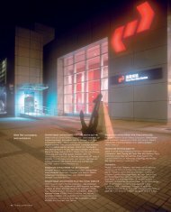
13. Roof structure at angle stations.<br />
For the roof structure, three alternative schemes were compared to identify the<br />
most economic solution, <strong>as</strong> opposed to the large portal frame structures originally<br />
proposed, which formed the b<strong>as</strong>is of the target cost contract during Stage 2 for<br />
both the AIAS and the NLSAS. The final scheme adopted is a trussed frame<br />
(Fig 13), which simplified connection details and only amounted to about half the<br />
steelwork weight of the Stage 2 scheme. Columns and bracing along the central<br />
gridline were limited to locations agreed with the ropeway designer.<br />
Towers<br />
General<br />
There are eight towers in all, five of them in the country park (Towers 3, 4, 5, 6,<br />
and 7). The building and civil engineering contract 5201 included construction of<br />
the foundations and pilecaps within <strong>Arup</strong>’s scope of works. <strong>Arup</strong> also took over<br />
all natural terrain hazard <strong>as</strong>sessment and mitigation works <strong>as</strong>sociated with the<br />
foundation design in the country park, including identification of hazards, boulder<br />
surveys, rock joint mapping, design of mitigation me<strong>as</strong>ures like soil nailing and<br />
boulder stabilization, and regulatory approval processes.<br />
Foundations<br />
Vertical pre-bored H-piles were adopted for Towers 1 and 2B, and a combination<br />
of vertical and raking minipiles for Towers 2A and 3-7, with rock sockets to resist<br />
tension and compression. Minipiles were the preferred option for works in the<br />
country park <strong>as</strong> they could be installed with small rigs.<br />
A typical tower foundation comprises a series of vertical and raking minipiles<br />
in two directions under a single pilecap supporting each tower leg. The ropeway<br />
designer supplied data on the most critical loads for each support, including the<br />
effects of dead load, imposed loads, wind, and earthquake loads (<strong>as</strong> required by<br />
MTRCL) from both the tower steel superstructure and the cable car system.<br />
The maximum and minimum loads in each of the three axes, together with<br />
co-existing loads, were analyzed to give all possible load combinations from the<br />
superstructure and the cable car above. Hundreds had to be <strong>as</strong>sessed so <strong>as</strong> to<br />
determine the loads in the piles and for the design of the pilecaps.<br />
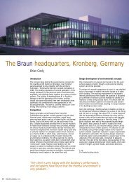
14. Tower 2B.<br />
492.0m<br />
Tower 4<br />
49m<br />
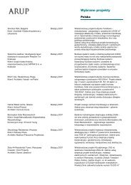
Table 1: Tower and station distances<br />
Tung Chung terminal<br />
Tower 1<br />
Tower 2A<br />
Airport Island angle station<br />
Tower 2B<br />
Tower 3<br />
Tower 4<br />
Tower 5<br />
Nei Lak Shan angle station<br />
Tower 6<br />
Tower 7<br />
<strong>Ngong</strong> <strong>Ping</strong> terminal<br />
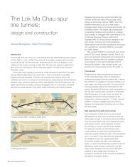
Table 2: Tower heights<br />
Horizontal<br />
distance<br />
Tower 1 37 12 2.5<br />
Tower 2A 21 7 2.5<br />
Tower 2B 50 16 2.5<br />
Tower 3 17 7 7<br />
Tower 4 49 16 2.5<br />
Tower 5 44 13 2.5<br />
Tower 6 27 9 2.5<br />
Tower 7 46 16 4<br />
* Below tower head<br />
Tower height<br />
in the axis<br />
Inclined<br />
distance<br />
1 16 117<br />
355 355<br />
51 52<br />
86 88<br />
1490 <strong>15</strong>12<br />
1048 1063<br />
83 3 838<br />
29 30<br />
161 161<br />
96 9 974<br />
38 6 388<br />
Tower width<br />
at b<strong>as</strong>e<br />
Tower width<br />
at top*<br />
The <strong>Arup</strong> Journal 1/2008 9