A Survey of Unstructured Mesh Generation Technology
A Survey of Unstructured Mesh Generation Technology
A Survey of Unstructured Mesh Generation Technology

Create successful ePaper yourself
Turn your PDF publications into a flip-book with our unique Google optimized e-Paper software.
A <strong>Survey</strong> <strong>of</strong> <strong>Unstructured</strong> <strong>Mesh</strong> <strong>Generation</strong> <strong>Technology</strong><br />
Steven J. Owen<br />
Department <strong>of</strong> Civil and Environmental Engineering, Carngie Mellon University, Pittsburgh, PA.<br />
and<br />
ANSYS Inc., Canonsburg, PA.<br />
steve.owen@ansys.com<br />
Abstract<br />
A brief survey <strong>of</strong> some <strong>of</strong> the fundamental algorithms in unstructured mesh generation is presented.<br />
Included is a discussion and categorization <strong>of</strong> triangle, tetrahedral, quadrilateral and hexahedral mesh<br />
generation methods currently in use in academia and industry. Also included is a brief discussion <strong>of</strong><br />
smoothing, cleanup and refinement algorithms. An informal survey <strong>of</strong> currently available mesh generation<br />
s<strong>of</strong>tware is also provided comparing some <strong>of</strong> their main features.<br />
1. Introduction<br />
Automatic unstructured mesh generation is a relatively new field. Within its short life span we have seen<br />
tremendous advances in many diverse fields. Once in a while, it is useful to step back from our own<br />
expertise and look at the entire picture <strong>of</strong> what is going on in the field. The purpose <strong>of</strong> this survey is to<br />
give some perspective to what the current trends are in mesh generation and outline some <strong>of</strong> the major<br />
technology areas, who is working in these fields and what s<strong>of</strong>tware is available.<br />
Probably the simplest approach is to first break down the technology based on the shape <strong>of</strong> element<br />
generated. We will consider triangle and quad generation methods in 2D and tetrahedral and hexahedral<br />
methods in 3D. Straddled between 2D and 3D, we have surface meshing, which has it’s own set <strong>of</strong> issues.<br />
In addition we have another set <strong>of</strong> issues dealing with post processing <strong>of</strong> the mesh including smoothing,<br />
cleanup and refinement. Within each <strong>of</strong> these issues, have emerged a few clear categories <strong>of</strong> algorithms,<br />
which tend to dominate much <strong>of</strong> the literature and s<strong>of</strong>tware. Not included in this survey are a wide variety<br />
<strong>of</strong> equally important related topics such as adaptive, anisotropic and parallel mesh generation as well as<br />
data structure and geometry management issues. Because <strong>of</strong> the immense scope <strong>of</strong> the field <strong>of</strong> unstructured<br />
mesh generation, I have limited this survey to include what I consider the more fundamental aspects <strong>of</strong> the<br />
field. Since I do not purport to be an expert in all fields <strong>of</strong> mesh generation, this will be at best, a cursory<br />
look at the main issues in each category.<br />
1.1 S<strong>of</strong>tware <strong>Survey</strong><br />
As part <strong>of</strong> this paper, I conducted an informal survey <strong>of</strong> s<strong>of</strong>tware vendors, research labs and educational<br />
institutions that develop mesh and grid generation s<strong>of</strong>tware. The purpose was to get a broad picture <strong>of</strong> who<br />
was currently involved in developing s<strong>of</strong>tware and what common algorithms were employed. The results<br />
<strong>of</strong> the survey are included as an appendix to this paper. They are also posted on the World Wide Web 1 .<br />
From the over 100 surveys mailed, approximately 80 responded. While the emphasis <strong>of</strong> the survey was<br />
unstructured, many unstructured codes are also included.<br />
The survey is certainly not a complete list <strong>of</strong> all those developing s<strong>of</strong>tware, but it does illustrate the wide<br />
range <strong>of</strong> mesh generation technology currently available. Included are simple research codes used by only<br />
a few people, to commercial codes integrated within complex analysis packages.
1.2 Structured vs. <strong>Unstructured</strong><br />
This survey paper focuses on unstructured meshing technology. There is a large group <strong>of</strong> literature 2,3 and<br />
s<strong>of</strong>tware 4 that deals with structured meshing commonly referred to as “grid generation”. Strictly speaking,<br />
a structured mesh can be recognized by all interior nodes <strong>of</strong> the mesh having an equal number <strong>of</strong> adjacent<br />
elements. For our purposes, the mesh generated by a structured grid generator is typically all quad or<br />
hexahedral. Algorithms employed generally involve complex iterative smoothing techniques that attempt to<br />
align elements with boundaries or physical domains. Where non-trivial boundaries are required, “blockstructured”<br />
techniques can be employed which allow the user to break the domain up into topological<br />
blocks. Structured grid generators are most commonly used within the CFD field, where strict alignment <strong>of</strong><br />
elements can be required by the analysis code or necessary to capture physical phenomenon.<br />
<strong>Unstructured</strong> mesh generation, on the other hand, relaxes the node valence requirement, allowing any<br />
number <strong>of</strong> elements to meet at a single node. Triangle and Tetrahedral meshes are most commonly thought<br />
<strong>of</strong> when referring to unstructured meshing, although quadrilateral and hexahedral meshes can also be<br />
unstructured. While there is certainly some overlap between structured and unstructured mesh generation<br />
technologies, the main feature which distinguish the two fields are the unique iterative smoothing<br />
algorithms employed by structured grid generators.<br />
2.0 Tri/Tetrahedral <strong>Mesh</strong>ing<br />
Triangle and tetrahedral meshing are by far the most common forms <strong>of</strong> unstructured mesh generation.<br />
Most techniques currently in use can fit into one <strong>of</strong> three main categories:<br />
1. Octree<br />
2. Delaunay<br />
3. Advancing Front<br />
Although there is certainly a difference in complexity when moving from 2D to 3D, the algorithms<br />
discussed are for the most part applicable for both triangle and tetrahedral mesh generation.<br />
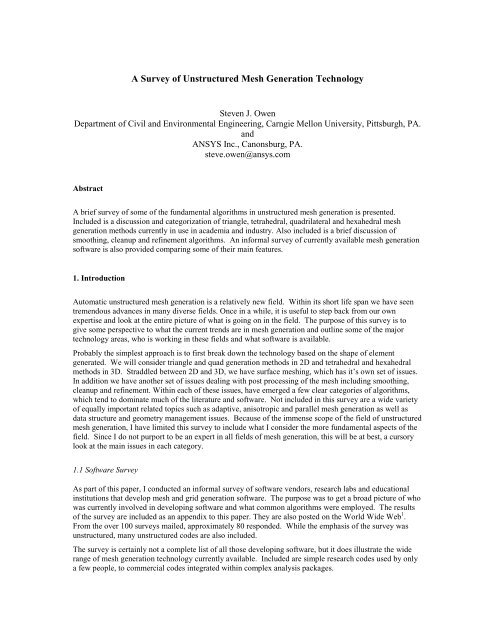
2.1 Octree<br />
The Octree technique was primarily developed in the 1980s by Mark Shephard’s 5,6 group at Rensselaer.<br />
With this method, cubes containing the geometric model are recursively subdivided until the desired<br />
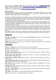
resolution is reached. Figure 1 shows the equivalent two-dimensional quadtree decomposition <strong>of</strong> a model.<br />
Irregular cells are then created where cubes intersect the surface, <strong>of</strong>ten requiring a significant number <strong>of</strong><br />
surface intersection calculations. Tetrahedra are generated from both the irregular cells on the boundary and<br />
the internal regular cells. The Octree technique does not match a pre-defined surface mesh, as an<br />
advancing front or Delaunay mesh might, rather surface facets are formed wherever the internal octree<br />
structure intersects the boundary. The resulting mesh also will change as the orientation <strong>of</strong> the cubes in the<br />
octree structure is changed and can also require. To ensure element sizes do not change too dramatically, a<br />
maximum difference in octree subdivision level between adjacent cubes can be limited to one. Smoothing<br />
and cleanup operations can also be employed to improve element shapes.<br />
Figure 1. Quadtree decomposition <strong>of</strong> a simple 2D object<br />
From the survey, only four <strong>of</strong> the 38 codes generating tetrahedral meshes reported using some form <strong>of</strong><br />
octree technique. SCOREC 7 at Rensselaer develops a set <strong>of</strong> mesh generation tools called MEGA that
utilizes the Octree technique that is available through their partners program. A public domain octree mesh<br />
generator called QMG 8 is available from Steve Vivasis at Cornell.<br />
2.2 Delaunay<br />
By far the most popular <strong>of</strong> the triangle and tetrahedral meshing techniques are those utilizing the Delaunay 9<br />
criterion. The Delaunay criterion, sometimes called the “empty sphere” property simply stated, says that<br />
any node must not be contained within the circumsphere <strong>of</strong> any tetrahedra within the mesh. A circumsphere<br />
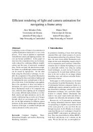
can be defined as the sphere passing through all four vertices <strong>of</strong> a tetrahedron. Figure 2 is a simple twodimensional<br />
illustration <strong>of</strong> the criterion. Since the circumcircles <strong>of</strong> the triangles in (a) do not contain the<br />
other triangle’s nodes, the empty circle property is maintained. Although the Delaunay criterion has been<br />
known for many years, it was not until the work <strong>of</strong> Charles Lawson 10 and Dave Watson 11 that the criterion<br />
was utilized for developing algorithms to triangulate a set <strong>of</strong> vertices. A simple public domain 3D<br />
Delaunay triangulation program called Qhull is available from the University <strong>of</strong> Minneapolis. The criterion<br />
was later used in developing meshing algorithms by Timothy Baker 12 at Princeton, Nigel Weatherill 13 at<br />
Swansea, Paul-Louis George 14 at INRIA among others.<br />
(a)<br />
(b)<br />
Figure 2. Example <strong>of</strong> Delaunay criterion. (a) maintains the criterion while (b) does not.<br />
The Delaunay criterion in itself, is not an algorithm for generating a mesh. It merely provides the criteria<br />
for which to connect a set <strong>of</strong> existing points in space. As such it is necessary to provide a method for<br />
generating node locations within the geometry. A typical approach is to first mesh the boundary <strong>of</strong> the<br />
geometry to provide an initial set <strong>of</strong> nodes. The boundary nodes are then triangulated according to the<br />
Delaunay criterion. Nodes are then inserted incrementally into the existing mesh, redefining the triangles<br />
or tetrahedra locally as each new node is inserted to maintain the Delaunay criterion. It is the method that<br />
is chosen for defining where to locate the interior nodes that distinguishes one Delaunay algorithm from<br />
another.<br />
2.2.1 Point insertion<br />
The simplest point insertion approach is to define nodes from a regular grid <strong>of</strong> points covering the domain<br />
at a specified nodal density. In order to provide for varying element sizes, a user specified sizing function<br />
can also be defined and nodes inserted until the underlying sizing function is satisfied. Another approach is<br />
for nodes to be recursively inserted at triangle or tetrahedral centroids. Weatherill and Hassan 13 propose a<br />
tetrahedral mesh generation scheme where nodes are inserted at a tetrahedron’s centroid provided the<br />
underlying sizing function is not violated.<br />
An alternate approach is to define new nodes at element circumcircle/sphere centers as proposed by Chew 15<br />
and Ruppert 16 . When a specific order <strong>of</strong> insertion is followed, this technique is <strong>of</strong>ten referred to as<br />
“Guaranteed Quality” as triangles can be generated with a minimum bound on any angle in the mesh.<br />
Jonathon Shewchuk 17 at CMU has developed a 2D version <strong>of</strong> this algorithm and makes it available free <strong>of</strong><br />
charge for research purposes.<br />
Similar to the circumcircle point insertion method, another technique introduced by Rebay 18 is the socalled,<br />
Voronoi-segment point insertion method. A Voronoi segment can be defined as the line segment<br />
between the circumcircle centers <strong>of</strong> two adjacent triangles or tetrahedra. The new node is introduced at a
point along the Voronoi segment in order to satisfy the best local size criteria. This method tends to<br />
generate very structured looking meshes with six triangles at every internal node.<br />
Another method, introduced by Marcum 19 is an advancing front approach to node insertion. Nodes are<br />
inserted incrementally, but added from the boundary towards the interior. Each facet is examined to<br />
determine the ideal location for a new fourth node on the interior <strong>of</strong> the existing Delaunay mesh. The node<br />
is then inserted and local reconnection is performed. This method tends to generate elements well aligned<br />
with the boundary with a very structured appearance to the mesh. Dave Marcum provides both a 2D and<br />
3D version <strong>of</strong> his mesh generators through the ERC 20 at Mississippi State.<br />
One straightforward method used by INRIA 21 in their mesh generator GSH3D 22 , is point insertion along<br />
edges. A set <strong>of</strong> candidate vertices is generated by marching along the existing internal edges <strong>of</strong> the<br />
triangulation at a given spacing ratio. Nodes are then inserted incrementally, discarding nodes that would<br />
be too close to an existing neighbor. This process is continued recursively until a background sizing<br />
function is satisfied.<br />
A variety <strong>of</strong> other methods for point insertion have also been proposed, but most have a similar flavor to<br />
those discussed above<br />
2.2.2 Boundary Constrained Triangulation<br />
In many finite element applications, there is a requirement that an existing surface triangulation be<br />
maintained. In most Delaunay approaches, before internal nodes are generated, a three dimensional<br />
tessellation <strong>of</strong> the nodes on the geometry surface is produced. In this process, there is no guarantee that the<br />
surface triangulation will be satisfied. In many implementations, the approach is to tessellate the boundary<br />
nodes using a standard Delaunay algorithm without regard for the surface facets. A second step is then<br />
employed to force or recover the surface triangulation. Of course by doing so, the triangulation may no<br />
longer be strictly “Delaunay”, hence the term “Boundary Constrained Delaunay Triangulation”.<br />
In two dimensions the edge recovery is relatively straightforward. George 23 describes how the edges <strong>of</strong> a<br />
triangulation may be recovered by iteratively swapping triangle edges. The process is considerably more<br />
complex in three dimensions, since after recovering all edges in the surface triangulation, there is no<br />
guarantee that the surface facets themselves will be recovered. Additional facet recovery operations can be<br />
required to maintain the surface triangulation. While the two dimensional recovery process is guaranteed<br />
to produce a boundary conforming triangulation, there are cases 24 in three dimensions where a valid<br />
triangulation can not be defined without first inserting additional vertices. This fact increases the<br />
complexity <strong>of</strong> any three dimensional boundary recovery procedure. Two different methods presented in the<br />
literature for recovery <strong>of</strong> the boundary include George 14 and Weatherill 13 .<br />
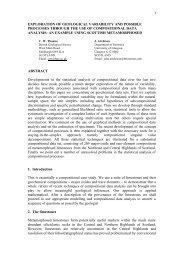
In the first approach defined by George 14 and implemented in INRIA’s GSH3D 22 s<strong>of</strong>tware, edges are<br />
recovered by performing a series <strong>of</strong> tetrahedral transformations by swapping two adjacent tetrahedra for<br />
three, as shown in Figure 3. Where a swap cannot resolve the edge, nodes must sometimes be inserted.<br />
After edges have been recovered, in order to recover the face, additional transformations are performed,<br />
mostly characterized by swapping three adjacent tetrahedra at an edge for two. More complex<br />
transformations or additional nodes can be inserted during the face recovery phase if the transformations do<br />
not resolve the surface facet.<br />
C<br />
C<br />
D<br />
E<br />
D<br />
E<br />
A<br />
A<br />
B<br />
B<br />
Figure 3. Tetrahedral transformation where two tets are swapped for three.
The second approach defined by Weatherill also involves an edge recovery phase and a face recovery<br />
phase. The main difference with this approach is that rather than attempting to transform the tetrahedra to<br />
recover edges and faces, nodes are inserted directly into the triangulation wherever the surface edge or facet<br />
cuts non-conforming tetrahedra. This process temporarily adds additional nodes to the surface. Once the<br />
surface facets have been recovered, additional nodes that were inserted to facilitate the boundary recovery<br />
are deleted and the resulting local void retriangulated.<br />
Another approach presented by Barry Joe 25 , is able to avoid the boundary recovery problem altogether.<br />
Provided the geometry is convex, Joe is able to define a boundary conforming tetrahedral mesh. The<br />
emphasis in this method, rather than attempting to repair the boundary <strong>of</strong> an arbitrary non-convex surface<br />
triangulation, is to decompose the geometry into convex regions that can be separately processed. An older<br />
unsupported public domain version <strong>of</strong> Barry Joe’s code, Geompack, is available from the University <strong>of</strong><br />
Alberta 26 via anonymous ftp.<br />
2.3 Advancing Front<br />
Another very popular family <strong>of</strong> triangle and tetrahedral mesh generation algorithms is the advancing front,<br />
or moving front method. Two <strong>of</strong> the main contributors to this method are Rainald Lohner 27,28 at George<br />
Mason University and S. H. Lo 29,30 at the University <strong>of</strong> Hong Kong. In this method, the tetrahedra are built<br />
progressively inward from the triangulated surface. An active front is maintained where new tetrahedra are<br />
formed. Figure 4 is a simple two-dimensional example <strong>of</strong> the advancing front, where triangles have been<br />
formed at the boundary. As the algorithm progresses, the front will advance to fill the remainder <strong>of</strong> the<br />
area with triangles. In three-dimensions, for each triangular facet on the front, an ideal location for a new<br />
fourth node is computed. Also determined are any existing nodes on the front that may form a well-shaped<br />
tetrahedron with the facet. The algorithm selects either the new fourth node or an existing node to form the<br />
new tetrahedron based on which will form the best tetrahedron. Also required are intersection checks to<br />
ensure that tetrahedron do not overlap as opposing fronts advance towards each other. A sizing function<br />
can also be defined in this method to control element sizes. Lohner 28 proposed using a course Delaunay<br />
mesh <strong>of</strong> selected boundary nodes over which the sizing function could be quickly interpolated. A version<br />
<strong>of</strong> S. H. Lo’s advancing front mesh generator is available with the ANSYS 31 suite <strong>of</strong> mesh generation tools.<br />
Figure 4. Example <strong>of</strong> advancing front where one layer <strong>of</strong> triangles has been placed<br />
A form <strong>of</strong> the advancing front method, sometimes called “advancing layers”, is also used for generating<br />
boundary layers for CFD, Navier-Stokes applications. This method lends itself well to control <strong>of</strong> element<br />
sizes near the boundary. Pirzadeh 32 presents a method where the elements are stretched in the direction <strong>of</strong><br />
the boundary, the expected direction <strong>of</strong> fluid flow. A public domain version <strong>of</strong> Pirzadeh’s code, VGRID 33<br />
is available from NASA, Langley.<br />
3. Quad/Hexahedral <strong>Mesh</strong>ing<br />
Automatic unstructured mesh generation algorithms have lent themselves more readily to triangle and<br />
tetrahedral meshing. As a result, most <strong>of</strong> the literature and s<strong>of</strong>tware are triangle and tetrahedral. In spite <strong>of</strong><br />
this, there is a significant group <strong>of</strong> literature that focuses on unstructured quad and hexahedral methods.<br />
<strong>Unstructured</strong> quad 34 and hex 35 meshing s<strong>of</strong>tware have also become widely available in recent years. Unlike
triangle and tetrahedral methods, extension from a 2D quadrilateral algorithm to a 3D hexahedral method is<br />
not generally straightforward.<br />
3.1 Mapped <strong>Mesh</strong>ing<br />
When the geometry <strong>of</strong> the domain is applicable, quad or hex mapped meshing 36 will generally produce the<br />
most desirable result. Although mapped meshing is considered a structured method, it is quite common for<br />
unstructured codes to provide a mapped meshing option. For mapped meshing to be applicable, opposite<br />
edges <strong>of</strong> the area to be meshed must have equal numbers <strong>of</strong> divisions. In 3D, each opposing face <strong>of</strong> a<br />
topological cube must have the same surface mesh. This can <strong>of</strong>ten be impossible for an arbitrary geometric<br />
configuration or can involve considerable user interaction to decompose geometry into mapped meshable<br />
regions and assign boundary intervals. In order to reduce human interaction, research has be done in recent<br />
years through the CUBIT 37 project at Sandia National Labs to automatically recognize features 38 and<br />
decompose geometry 39 into separate mapped meshable areas and volumes. Work has also been done to<br />
automate interval assignments 40 .<br />
Another category <strong>of</strong> mapped meshing, also developed as part <strong>of</strong> the CUBIT 37 project is referred to as submapping<br />
41 . This method, rather than decomposing the geometry directly, determines an appropriate virtual<br />
decomposition based on corner angles and edge directions. The separate map-meshable regions are then<br />
meshed separately. This method is suitable for blocky shapes and volumes that have well defined corners<br />
and cube-like regions.<br />
Sweeping, sometimes referred to as 2 ½-D meshing, is another class <strong>of</strong> mapped hexahedral meshing. A<br />
quadrilateral mesh can be swept through space along a curve. Regular layers <strong>of</strong> hexahedra are formed at<br />
specified intervals using the same topology as the quadrilateral mesh. This technique can be generalized to<br />
mesh certain classes <strong>of</strong> volumes by defining so-called source and target surfaces. Provided the source and<br />
target surface have similar topology and the surfaces are connected by a set <strong>of</strong> map-meshable surfaces, the<br />
quad elements <strong>of</strong> the source area can be swept through the volume to generate hexahedra as shown in<br />
Figure 5. Care must be taken in locating internal nodes during the sweeping process and several papers 42,43<br />
have been presented addressing this issue.<br />
sweep<br />
target<br />
source<br />
Figure 5. Hex elements generated by sweeping<br />
Blacker 44 generalizes and extends the applicability <strong>of</strong> sweeping when he introduces the Cooper Tool. The<br />
Cooper tool allows for multiple source and target surfaces while still requiring a single sweep direction.<br />
With this tool, the topology is allowed to branch or split along the sweep direction. In addition, the<br />
topology <strong>of</strong> source and target surfaces are not required to be similar. With these requirements relaxed, a<br />
greater subset <strong>of</strong> geometry may be meshed with generally very high quality elements. The cooper tool is<br />
provided as part <strong>of</strong> the Fluent pre-processor, Gambit 45 .<br />
3.2 <strong>Unstructured</strong> Quad <strong>Mesh</strong>ing<br />
<strong>Unstructured</strong> quadrilateral meshing algorithms can, in general, be grouped into two main categories: direct<br />
and indirect approaches. With an indirect approach, the domain is first meshed with triangles. Various<br />
algorithms are then employed to convert the triangles into quadrilaterals. With a direct approach,
quadrilaterals are placed on the surface directly, without first going through the process <strong>of</strong> triangle<br />
meshing.<br />
3.2.1 Indirect Methods<br />
One <strong>of</strong> the simplest methods for indirect quadrilateral mesh generation includes dividing all triangles into<br />
three quadrilaterals, as shown in Figure 6. This method guarantees an all-quadrilateral mesh, but a high<br />
number <strong>of</strong> irregular nodes are introduced into the mesh resulting in poor element quality. An alternate<br />
algorithm is to combine adjacent pairs <strong>of</strong> triangles to form a single quadrilateral as shown in Figure 7.<br />
While the element quality increases using this method, a large number <strong>of</strong> triangles may be left.<br />
Figure 6. Quad mesh generated by splitting each triangle into three quads<br />
Figure 7. Quad-dominant mesh generated by combining triangles.<br />
The triangle combining method can be improved, if some care is taken in the order in which triangles are<br />
combined. In an effort to maximize the number <strong>of</strong> quadrilaterals, Lo 46 defined an algorithm that suggested<br />
several heuristic procedures for the order in which triangles could be combined. The result is a quaddominant<br />
mesh containing a minimal number <strong>of</strong> triangles. Johnston 47 proposes additional local element<br />
splitting and swapping strategies to increase the number and quality <strong>of</strong> quads.<br />
Lee 48 later enhances Lo’s 46 strategy by including local triangle splitting. In addition, an advancing front<br />
approach is used over the initial triangles. An initial set <strong>of</strong> fronts is defined consisting <strong>of</strong> the edges <strong>of</strong><br />
triangles at the boundary <strong>of</strong> the domain. Triangles are systematically combined at the front, advancing<br />
towards the interior <strong>of</strong> the area. Each time a set <strong>of</strong> triangles is combined the front advances. The front<br />
always defines the division between quadrilaterals already formed and triangles yet to be combined. With<br />
this technique, Lee is able to guarantee an all-quadrilateral mesh, provided the initial number <strong>of</strong> edges on<br />
the boundary is even.<br />
Since all operations are local, indirect methods have the advantage <strong>of</strong> being very fast. Global intersection<br />
checks are not necessary as is required with some forms <strong>of</strong> direct methods. The drawback to indirect<br />
methods is that there are typically many irregular nodes left in the mesh. Even if few irregular nodes exist,<br />
there is no guarantee that the elements will align with the boundary, a desirable property for some<br />
applications. Some <strong>of</strong> the irregular nodes can be reduced, and hence element quality increased by<br />
performing topological clean-up operations (discussed later).<br />
Another method recently introduced by the author, known as Quad Morphing 49 also utilizes an advancing<br />
front approach to convert triangles to quads, but is able to significantly reduce the number <strong>of</strong> irregular<br />
nodes in the mesh. With this approach, local edge swaps are performed and additional nodes introduced in<br />
order to ensure boundary alignment and orthogonality. Any number <strong>of</strong> triangles may be deleted to create a<br />
single quad.
3.2.2 Direct Methods<br />
Many methods for direct generation <strong>of</strong> quad meshes have been proposed. Among these methods, there<br />
appears to be two main categories. The first are methods that rely on some form <strong>of</strong> decomposition <strong>of</strong> the<br />
domain into simpler regions than can be resolved by one <strong>of</strong> a series <strong>of</strong> templates. The second category are<br />
those that utilize a moving front method for direct placement <strong>of</strong> nodes and elements.<br />
3.2.2.1 Quad <strong>Mesh</strong>ing by Decomposition<br />
The quad-tree decomposition technique proposed by Baehmann 50 is among the first methods utilizing<br />
decomposition <strong>of</strong> the area for quadrilateral meshing. After an initial decomposition <strong>of</strong> the 2D space into a<br />
quad-tree based on local feature sizes, quadrilateral elements are fitted into the quad-tree leaves, adjusting<br />
nodes in order to conform to the boundary.<br />
Talbert 51 later introduces another decomposition technique. With this approach, the domain is recursively<br />
subdivided into simple polygonal shapes. The resulting polygons satisfy a limited number <strong>of</strong> templates into<br />
which quadrilateral elements are inserted. Chae 52 has recently proposed enhancements to Talbert’s<br />
algorithm with similar work presented by Nowottny 53 .<br />
Quadrilateral meshing utilizing a medial axis decomposition <strong>of</strong> the domain was first introduced by Tam 54 .<br />
The medial axis can be thought <strong>of</strong> as a series <strong>of</strong> lines and curves generated from the midpoint <strong>of</strong> a maximal<br />
circle as it is rolled through the area (Figure 8). Having decomposed the area into simpler regions, sets <strong>of</strong><br />
templates are then employed to insert quadrilaterals into the domain. Linear programming techniques are<br />
used in order to maintain compatibility <strong>of</strong> element divisions between adjoining regions <strong>of</strong> the domain.<br />
medial axis<br />
Figure 8. Decomposition <strong>of</strong> an area using the medial axis<br />
Joe 55 also utilizes decomposition algorithms to decompose the area into convex polygons. Using<br />
techniques previously developed for triangle mesh generation 56 , Joe constructs a boundary constrained<br />
quadrilateral mesh within each convex sub-domain <strong>of</strong> the area.<br />
3.2.2.2 Advancing Front Quad <strong>Mesh</strong>ing<br />
Zhu 57 is among the first to propose a quadrilateral meshing algorithm using an advancing front approach.<br />
Starting with an initial placement <strong>of</strong> nodes on the boundary, individual elements are formed by projecting<br />
edges towards the interior. Two triangles are formed using traditional triangle advancing front methods<br />
and then combined to form a single quadrilateral.<br />
The paving algorithm introduced by Blacker and Stephenson 58 , presents a method for forming complete<br />
rows <strong>of</strong> elements starting from the boundary and working in. Methods for projection <strong>of</strong> nodes, handling <strong>of</strong><br />
special geometric situations and intersection <strong>of</strong> opposing fronts are discussed. Cass 59 further developed<br />
paving, by generalizing the method for three-dimensional surfaces. White 60 recently proposed<br />
enhancements to the paving algorithm suggesting individual placement <strong>of</strong> elements rather than complete<br />
rows. The paving algorithm is currently implemented as part <strong>of</strong> the CUBIT 37 s<strong>of</strong>tware as well as several<br />
commercial packages including MSC Patran 61 and Fluent’s Gambit 45 s<strong>of</strong>tware.
3.3 <strong>Unstructured</strong> Hex <strong>Mesh</strong>ing<br />
Similar to quadrilateral meshing, there are both direct and indirect methods for unstructured hex meshing.<br />
3.3.1 Indirect Methods<br />
Indirect methods, although not in wide use have been proposed for some applications 62 . Provided a solid<br />
can be tet meshed, each tetrahedron can be subdivided into four hexahedra as shown in Figure 9. Most<br />
finite element analysts, because <strong>of</strong> the poor element quality that will in general result, have rejected this<br />
solution.<br />
Figure 9. Decomposition <strong>of</strong> a tetrahedron into four hexahedra<br />
An equivalent indirect hexahedral mesh generation scheme that will combine tetrahedra, similar to<br />
combining triangles to form quadrilaterals has not been presented in the literature. The simplest<br />
tetrahedralization <strong>of</strong> a cube will contain five tetrahedra. An indirect method that combines tets to form<br />
hexes would therefore need to look for combinations <strong>of</strong> five or more tetrahedra to form a single hexahedra.<br />
This problem to date has not proved a reasonable nor tractable method for mesh generation.<br />
3.3.2 Direct Methods<br />
There are currently four distinct strategies proposed for unstructured all-hex mesh generation that are<br />
predominant in the literature:<br />
1. grid-based<br />
2. medial surface<br />
3. plastering<br />
4. whisker weaving<br />
3.3.2.1 Grid-Based<br />
The grid-based approach, proposed by Schneiders 63 involves generating a fitted three dimensional grid <strong>of</strong><br />
hex elements on the interior <strong>of</strong> the volume. Hex elements are added at the boundaries to fill gaps where the<br />
regular grid <strong>of</strong> hexes does not meet flush with the surface. This method, while robust, tends to generate<br />
poor quality elements at the boundary <strong>of</strong> the volume. Hex elements will in general not be aligned with the<br />
boundary. The resulting mesh generated from the grid-based approach is also highly dependent upon the<br />
orientation <strong>of</strong> the interior grid <strong>of</strong> hex elements. In addition, element sizes must be approximately all the<br />
same. In recent work, Weiler 64 and Schneiders 65 have introduced modifications that allow for significant<br />
transition in element sizes utilizing an octree decomposition <strong>of</strong> the domain. <strong>Mesh</strong> generators based on the<br />
grid-based approach are available in the Hexar 66 s<strong>of</strong>tware from Cray Research and in MARC’s Mentat 67<br />
s<strong>of</strong>tware.
3.3.2.2 Medial Surface<br />
Medial surface methods 68,69,70 involve an initial decomposition <strong>of</strong> the volume. As a direct extension <strong>of</strong> the<br />
medial axis method for quad meshing, the domain is subdivided by a set <strong>of</strong> medial surfaces, which can be<br />
thought <strong>of</strong> as the surfaces generated from the midpoint <strong>of</strong> a maximal sphere as it is rolled through the<br />
volume. The decomposition <strong>of</strong> the volume by medial surfaces is said to generate map meshable regions. A<br />
series <strong>of</strong> templates for the expected topology <strong>of</strong> the regions formed by the medial surfaces are utilized to<br />
fill the volume with hexahedra. Linear programming is used to ensure element divisions match from one<br />
region to another. This method, while proving useful for some geometry, has been less than reliable for<br />
general geometry. Robustness issues in generating the medial surfaces as well as providing for all cases <strong>of</strong><br />
regions defined by the medial surfaces has proved to be a difficult problem. Medial surface methods are<br />
incorporated into the FEGS’ CADFix 71 hexahedral mesh generator and within Solidpoint’s Turbomesh 72<br />
s<strong>of</strong>tware.<br />
3.3.2.3 Plastering<br />
Plastering 73,74 is an attempt to extend the paving algorithm to three dimensions. With this method, elements<br />
are first placed starting with the boundaries and advancing towards the center <strong>of</strong> the volume as shown in<br />
Figure 10. A heuristic set <strong>of</strong> procedures for determining the order <strong>of</strong> element formation is defined. Similar<br />
to other advancing front algorithms, a current front is defined consisting <strong>of</strong> all quadrilaterals. Individual<br />
quads are projected towards the interior <strong>of</strong> the volume to form hexahedra. In addition, plastering must<br />
detect intersecting faces and determine when and how to connect to pre-existing nodes or to seam faces.<br />
As the algorithm advances, complex interior voids may result, which in some cases are impossible to fill<br />
with all-hex elements. Existing elements, already placed by the plastering algorithm must sometimes be<br />
modified in order to facilitate placement <strong>of</strong> hexes towards the interior.<br />
Figure 10. Plastering process forming elements at the boundary.<br />
Currently, the plastering algorithm has not been proven to be reliable on a large class <strong>of</strong> problems.<br />
Although in many cases, several layers <strong>of</strong> hex elements may be successfully placed on the boundary <strong>of</strong> the<br />
volume, intersection and closure procedures are less than reliable. Sandia’s CUBIT 37 project is continuing<br />
research on plastering and makes it available in their s<strong>of</strong>tware.<br />
3.3.2.4 Whisker Weaving<br />
Whisker weaving, first introduced by Tautges and Blacker 75 , is based on the concept <strong>of</strong> the spatial twist<br />
continuum (STC) 76 . Tautges describes the STC as the dual <strong>of</strong> the hexahedral mesh, represented by an<br />
arrangement <strong>of</strong> intersecting surfaces which bisect hexahedral elements in each direction. Figure 11 shows a<br />
simple representation <strong>of</strong> the twist planes <strong>of</strong> the STC defined for a volume composed <strong>of</strong> only two hexahedra.<br />
The principal behind whisker weaving is to first construct the STC or dual <strong>of</strong> the hex mesh. With a<br />
complete STC, the hex elements can then be fitted into the volume using the STC as a guide. This is done<br />
by beginning with a topological representation <strong>of</strong> the loops formed by the intersection <strong>of</strong> the twist planes<br />
with the surface. The loops can be easily determined from an initial quad mesh <strong>of</strong> the surface. The<br />
objective <strong>of</strong> the whisker weaving algorithm is to determine where the intersections <strong>of</strong> the twist planes will
occur within the volume. Since this is done topologically, there are no actual intersection calculations<br />
performed. Once a valid topological representation <strong>of</strong> the twist planes has been achieved, hexes are then<br />
formed inside the volume. One hex is formed wherever three twist planes converge.<br />
The whisker weaving algorithm has achieved some success, but has yet to prove itself as robust and reliable<br />
for a wide variety <strong>of</strong> problems.<br />
Figure 11. The STC composed <strong>of</strong> four twist planes, for a solid composed <strong>of</strong> two hexahedra<br />
3.4 Hex-Dominant Methods<br />
Since most methods for all-hex meshing appear to be less than robust, some researchers have proposed<br />
using a mixed hexahedra/tetrahedra mesh. A hex-dominant approach appears to be satisfactory in many<br />
cases. One simple approach introduced by the author 77 is to manually subdivide the geometry into regions<br />
that will readily accept a mapped mesh and those that are more geometrically complex. Within the<br />
complex regions a tet mesh is defined. Wherever the tet elements interface directly with hex elements, a<br />
pyramid shaped element may be formed. This option is provided with the ANSYS 31 mesh generation<br />
s<strong>of</strong>tware.<br />
Tuchinsky 78 recently proposed an algorithm for combining both plastering and tetrahedral meshing<br />
technologies. Using the plastering algorithm, hex elements are advanced as far as possible into the volume.<br />
The remaining voids within the volume are then filled with tetrahedra. The user also has the option <strong>of</strong><br />
forming pyramid shaped elements at the interface between hex and tet elements. The CUBIT 37 s<strong>of</strong>tware<br />
now provides an option to allow a hex-dominant mesh.<br />
Min 79 also presents a similar method for hex-dominant meshing, utilizing <strong>of</strong>fset geometry from the<br />
boundaries in order to form layers <strong>of</strong> hexes. After a series <strong>of</strong> shrunken shells have been advanced towards<br />
the interior <strong>of</strong> the volume, the remainder <strong>of</strong> the volume is filled with tetrahedra. In addition to tets and<br />
hexes, Min introduces pyramid and wedge shaped elements where applicable.<br />
4. Surface <strong>Mesh</strong>ing<br />
Many <strong>of</strong> today’s mesh generation problems involve the formation <strong>of</strong> elements on arbitrary threedimensional<br />
surfaces. These surfaces are typically represented by NURBS, which have been generated<br />
within a commercial CAD package. The resulting surface elements can either be used directly as structural<br />
shell elements, or used as input to a volumetric mesh generator. In either case, the algorithms used for twodimensional<br />
mesh generation require some modification in order to generalize them for use on threedimensional<br />
surfaces. Surface mesh generation algorithms can be classified as either parametric space or<br />
direct 3D.
4.1 Parametric Space<br />
Parametric space algorithms will form elements in the two-dimensional parametric space <strong>of</strong> the surface.<br />
Since all NURBS surfaces have an underlying u-v representation, it can <strong>of</strong>ten be efficient to mesh in two<br />
dimensions and as a final step, map the u-v coordinates back to world space, x-y-z coordinates. The<br />
drawback to this method is that the elements formed in parametric space may not always form well-shaped<br />
elements in three dimensions once mapped back to the surface. To resolve this, parametric surface meshers<br />
can do one <strong>of</strong> two things: 1) modify or reparamaterize the underlying parametric representation so there is a<br />
reasonable mapping from parametric space to world space; or 2) modify the mesh generation algorithm so<br />
that stretched or anisotropic elements meshed in 2D will map back to well-shaped, isotropic elements in<br />
3D.<br />
The first method requires that in order to have a good paramaterization, the surface derivatives, (∆u, ∆v),<br />
should not vary widely over the domain. Some exact arc-length reparamaterizations have been defined in<br />
the literature 80 , but can be excessively costly. An approximate arc-length paramaterization or “warped<br />
parametric space” can be defined by selectively evaluating surface derivatives over the domain and<br />
adjusting local u-v values to hold the magnitude <strong>of</strong> ∆u, ∆v roughly constant. For many cases, a warped<br />
parametric space can generate reasonable surface meshes, but there are many problems that the<br />
reparamaterization cannot adequately resolve. For this reason, much <strong>of</strong> the literature on surface meshing<br />
focuses on the second option <strong>of</strong> forming anisotropic elements in 2D that will map back to isotropic<br />
elements in 3D.<br />
A common method used in practice is to take advantage <strong>of</strong> surface derivatives, ∆u, ∆v, easily computed<br />
from a NURBS surface. George and Borouchaki 81 propose the use <strong>of</strong> a metric derived from the first<br />
fundamental form <strong>of</strong> the surface. The metric is in the form <strong>of</strong> a 2X2 matrix and is used to transform<br />
vectors and distances in parametric space. With their Delaunay approach, the “empty circle” property,<br />
effectively becomes an “empty ellipse” property. Also included with the metric is the option to incorporate<br />
element sizing and stretching properties. A similar approach to parametric Delaunay surface meshing is<br />
presented by Chen and Bishop 82 and available in MARC’s Mentat 67 s<strong>of</strong>tware. Equivalent advancing front<br />
surface mesh generation algorithms, which utilize a metric derived from the first fundamental form <strong>of</strong> the<br />
surface are presented independently by Cuilliere 83 and Tristano 84 . Tristano’s implementation is available in<br />
a recent release <strong>of</strong> the ANSYS 31 mesh generation tools.<br />
4.2 Direct 3D<br />
Direct 3D surface mesh generators form elements directly on the geometry without regard to the parametric<br />
representation <strong>of</strong> the underlying geometry. In some cases where a parametric representation is not<br />
available or where the surface paramaterization is very poor, direct 3D surface mesh generators can be<br />
useful. Lau and Lo 85,86 present an advancing front approach for arbitrary 3D surfaces. In this method<br />
surface normals and tangents must be computed in order to compute the direction <strong>of</strong> the advancing front.<br />
In addition, a significant number <strong>of</strong> surface projections are required to ensure that new nodes remain on the<br />
surface. Also <strong>of</strong> significance is the increased complexity <strong>of</strong> the intersection calculations required to ensure<br />
that triangles on the surface do not overlap.<br />
A direct 3D implementation 59 <strong>of</strong> the paving 44 algorithm is also available in the CUBIT 37 s<strong>of</strong>tware. Similar<br />
issues regarding additional projection and evaluations are also <strong>of</strong> significance to 3D paving. Cass 59 defines<br />
a heuristic “sticky space” in order to detect intersecting or overlapping quadrilaterals.<br />
5. <strong>Mesh</strong> Post-processing<br />
It is rare that any mesh generation algorithm will be able to define a mesh that is optimal without some<br />
form <strong>of</strong> post-processing to improve the overall quality <strong>of</strong> the elements. The two main categories <strong>of</strong> mesh<br />
improvement include smoothing and clean-up. Smoothing includes any method that adjusts node locations<br />
while maintaining the element connectivity. Clean-up generally refers to any process that changes the<br />
element connectivity.
5.1 Smoothing<br />
Most smoothing procedures involve some form <strong>of</strong> iterative process that repositions individual nodes to<br />
improve the local quality <strong>of</strong> the elements. A wide variety <strong>of</strong> smoothing techniques have been proposed.<br />
These methods can generally be classified as follows:<br />
1. Averaging methods<br />
2. Optimization-based methods<br />
3. Physically-based methods<br />
4. Mid-node placement<br />
5.1.1 Averaging Methods<br />
Of the wide variety <strong>of</strong> smoothing algorithms, the simplest and most straight forward is Laplacian<br />
smoothing 87 . With this method, an internal node in the mesh is placed at the average location <strong>of</strong> any node<br />
connected to it by an edge. With little modification, this technique can be applicable for any element shape.<br />
Most smoothing procedures will iterate through all the internal nodes in the mesh several times until any<br />
individual node has not moved more than a specified tolerance. Although it has its problems, it is simple to<br />
implement and is in wide use. Similar to Laplacian, there are a variety <strong>of</strong> other smoothing techniques,<br />
which iteratively reposition nodes based on a weighted average <strong>of</strong> the geometric properties <strong>of</strong> the<br />
surrounding nodes and elements. Canann 88 provides an overview <strong>of</strong> some <strong>of</strong> the common methods in use.<br />
Averaging methods quite <strong>of</strong>ten also employ some form <strong>of</strong> additional constraint on the movement <strong>of</strong> a node.<br />
For example, because Laplacian smoothing alone sometimes has the tendency to invert or degrade the local<br />
element quality, a comparison <strong>of</strong> local element quality is made before and after the proposed move and the<br />
node moved only if element quality is improved. This is <strong>of</strong>ten referred to as constrained Laplacian<br />
smoothing. Canann 88 presents criteria for the movement <strong>of</strong> the node with this method.<br />
5.1.2 Optimization-Based Methods<br />
Rather than relying on heuristic averaging methods, some codes use optimization techniques to improve<br />
element quality. Optimization-based smoothing techniques measure the quality <strong>of</strong> the surrounding<br />
elements to a node and attempt to optimize by computing the local gradient <strong>of</strong> the element quality with<br />
respect to the node location. The node is moved in the direction <strong>of</strong> the increasing gradient until an<br />
optimum is reached. Canann 88 and Freitag 89 both present optimization-based smoothing algorithms.<br />
While maintaining that optimization-based smoothing techniques provide superior mesh quality, the<br />
computational time involved is generally too excessive to use in standard practice. Canann 88 and Freitag 90<br />
both recommend a combined Laplacian/optimzation-based approach. What is generally advocated is that<br />
Laplacian smoothing is done for the majority <strong>of</strong> the time, reverting to optimization based smoothing only<br />
when local element shape metrics drop below a certain threshold.<br />
5.1.3 Physically-Based Methods<br />
Another important area <strong>of</strong> mesh improvement includes methods that reposition nodes based on a simulated<br />
physically based attraction or repulsion force. Lohner 91 simulates the force between neighboring nodes as a<br />
system <strong>of</strong> springs interacting with each other. Shimada 92 and Bossen 93 view the nodes as the center <strong>of</strong><br />
bubbles that are repositioned to attain equilibrium. With changes in the magnitude and direction <strong>of</strong> interparticle<br />
forces, different anisotropic characteristics and element sizes can be achieved.<br />
5.1.4 Mid-node Placement<br />
While most smoothing methods focus on repositioning corner nodes, Salem 94 recently introduced a method<br />
providing criteria for repositioning mid-nodes on quadratic elements to improve element quality. This
method computes a region surrounding the mid-node known as the mid-node admissible space (MAS),<br />
shown in Figure 12, where the mid-node can safely be moved and maintain or improve element quality.<br />
A<br />
Figure 12. Mid-node admissible space for node at A<br />
5.2 Cleanup<br />
Like smoothing, there are a wide variety <strong>of</strong> methods currently employed to improve the quality <strong>of</strong> the mesh<br />
by making local changes to the element connectivities. Cleanup methods generally apply some criteria that<br />
must be met in order to perform a local operation. The criteria in general can be defined as: 1) shape<br />
improvement or 2) topological improvement.<br />
In addition, cleanup operations are generally not done alone, but are used in conjunction with smoothing.<br />
Freitag 95 describes how smoothing and cleanup may be combined to efficiently improve overall element<br />
quality.<br />
5.2.1 Shape improvement<br />
For triangle meshes, simple diagonal swaps are <strong>of</strong>ten performed. For each interior edge in the triangulation<br />
a check can be made to determine at what position the edge would effectively improve the overall or<br />
minimum shape metric <strong>of</strong> its two adjacent triangles. The Delaunay criteria can also be used to determine<br />
the position <strong>of</strong> an edge. For Tetrahedral meshes, Barry Joe 96 presents a series <strong>of</strong> local transformations that<br />
are designed to improve the element quality. These include swapping two adjacent interior tets sharing the<br />
same face for three tets (see Figure 3). Likewise, three tets can be replaced with two. Other more complex<br />
transformations are also defined.<br />
In some applications where mixed element meshes are supported, the element quality <strong>of</strong> two adjacent<br />
triangles may be preferable to a single poor quality quadrilateral. When this is the case, selected<br />
quadrilaterals may be split.<br />
In some cases, particularly with curved surfaces, the elements resulting from the mesh generator may<br />
deviate significantly from the underlying geometry. For a triangle mesh, edge swaps can be performed<br />
based on which local position <strong>of</strong> the edge will deviate least from the surface. Although not strictly a<br />
cleanup operation, local refinement <strong>of</strong> the mesh may also be considered to capture surface features.<br />
5.2.2 Topological Improvement<br />
A common method for improving meshes is to attempt to optimize the number <strong>of</strong> edges sharing a single<br />
node. This is sometimes referred to as node valence or degree. In doing so, it is assumed that the local<br />
element shapes will improve. For a triangle mesh there should optimally be 6 edges at a node and four<br />
edges at a node surrounded by quads. Whenever there is a node that does not have an ideal valence, the<br />
quality <strong>of</strong> the elements surrounding it will also be less than optimal. Performing local transformations to<br />
the elements can improve topology and hence element quality. Several methods have been proposed for<br />
improving node valence for both triangle 97 and quadrilateral 98,99 meshes.
For volumetric meshes, valence optimization becomes more complex. In addition to optimizing the<br />
number <strong>of</strong> edges at a node, the number <strong>of</strong> faces at an edge can also be considered. For tetrahedral meshes<br />
this can involve a complex series <strong>of</strong> local transformations. For hexahedral elements, valence optimization<br />
is generally not considered tractable. The reason for this is that local modifications to a hex mesh will<br />
typically propagate themselves to more than the immediate vicinity. One special case <strong>of</strong> cleanup in hex<br />
meshes used in conjunction with the whisker weaving algorithm is presented by Mitchell 100 .<br />
5.3 Refinement<br />
Element refinement procedures are numerous. For our purposes, refinement is defined as any operation<br />
performed on the mesh that effectively reduces the local element size. The reduction in size may be<br />
required in order to capture a local physical phenomenon, or it may be done simply to improve the local<br />
element quality. Some refinement methods in themselves can be considered mesh generation algorithms.<br />
Starting with a coarse mesh, a refinement procedure can be applied until the desired nodal density has been<br />
achieved. Quite frequently, refinement algorithms are used as part <strong>of</strong> an adaptive solution process, where<br />
the results from a previous solution provide criteria for mesh refinement. Methods have been proposed for<br />
triangle and tet refinement as well as quad and hex.<br />
5.3.1 Triangle/Tetrahedral Refinement<br />
Although there are certainly more methods defined, three <strong>of</strong> the principal methods for triangle and<br />
tetrahedral refinement include:<br />
1. Edge bisection<br />
2. Point insertion<br />
3. Templates<br />
5.3.1.1 Edge Bisection.<br />
Edge bisection involves splitting individual edges in the triangulation. As a result, the two triangles<br />
adjacent the edge are split into two. Extended to volumetric meshing, any tetrahedron sharing the edge to<br />
be split must also be split as illustrated in Figure 13. Rivara 101 proposes criteria for the splitting <strong>of</strong> edges<br />
based on the longest edge <strong>of</strong> a triangle or tetrahedron.<br />
B<br />
B<br />
C<br />
A<br />
A<br />
Figure 13. Edge bisection in a tetrahedral mesh. Edge A-B is split at point C, also splitting its surrounding<br />
tetrahedra.<br />
5.3.1.2 Point Insertion<br />
A simple approach to refinement is to insert a single node at the centroid <strong>of</strong> an existing element, dividing<br />
the triangle into three or tetrahedron into four. This method does not generally provide good quality<br />
elements, particularly after several iterations <strong>of</strong> the scheme. To improve upon the scheme, a Delaunay<br />
approach can be used that will delete the local triangles or tetrahedra and connect the node to the
triangulation maintaining the Delaunay criterion. Any <strong>of</strong> the Delaunay point insertion methods discussed<br />
previously could effectively be used for refinement.<br />
A<br />
A<br />
Figure 14. Example <strong>of</strong> Delaunay refinement, where point A is inserted.<br />
5.3.1.3 Templates<br />
A template refers to a specific decomposition <strong>of</strong> the triangle. One example is to decompose a single<br />
triangle into four similar triangles by inserting a new node at each <strong>of</strong> its edges as show in Figure 15. The<br />
equivalent tetrahedron template would decompose it into eight tetrahedra where each face <strong>of</strong> the tet has<br />
been decomposed into 4 similar triangles. To maintain a conforming mesh, additional templates can also<br />
be defined based on the number <strong>of</strong> edges that have been split. Staten 102 outlines the various templates<br />
needed to locally refine tetrahedra while maintaining a conforming mesh.<br />
A<br />
B<br />
Figure 15. Example <strong>of</strong> local triangle refinement using a template where elements at A and B are refined<br />
5.3.2 Quad/Hex Refinement<br />
Because <strong>of</strong> the structured nature <strong>of</strong> quad and hex meshes, the point insertion and edge bisection methods<br />
are generally not applicable. The main methods used for quad and hex refinement involve decomposing<br />
the elements based on a set <strong>of</strong> predefined templates. Both Schneiders 103 and Staten 98 propose algorithms<br />
and a series <strong>of</strong> templates for element decomposition. An example <strong>of</strong> local quad refinement is shown in<br />
Figure 16. In order to maintain a conforming mesh, some quad and hex refinement schemes will <strong>of</strong>ten<br />
necessarily introduce triangle or alternate shaped elements including tetrahedra and pentahedra.<br />
A<br />
B<br />
Figure 16. Example <strong>of</strong> local quad refinement where elements at A and B are refined by one half.
6. Conclusion<br />
This survey has touched only briefly on some <strong>of</strong> the main issues and algorithms used in unstructured mesh<br />
generation. There are many more important aspects <strong>of</strong> unstructured mesh generation that were not<br />
addressed. Due to time and space constraints, it was not intended to be a comprehensive overview <strong>of</strong> the<br />
subject. Instead, it was the intent to focus on some <strong>of</strong> the more fundamental algorithms and procedures.<br />
Often times in the research and development <strong>of</strong> s<strong>of</strong>tware, we tend to forget what has gone before us, or fail<br />
to look at what is already readily available. The most efficient way to provide new and innovative<br />
technology is to build on the accomplishments <strong>of</strong> others. We should recognize the innovations and<br />
creativity <strong>of</strong> others in the field and try to improve upon what has gone before.<br />
References<br />
1 Steven J. Owen, (1998) <strong>Mesh</strong>ing S<strong>of</strong>tware <strong>Survey</strong>, web page: http://www.andrew.cmu.edu/user/sowen/s<strong>of</strong>tsurv.html<br />
2 Joe F. Thompson, (1985) “Numerical Grid <strong>Generation</strong>, Foundation and Applications”, Elsevier. Posted on www at<br />
http://www.erc.msstate.edu/education/gridbook/index.html<br />
3 Joe F. Thompson, (1996) “A Reflection on Grid generation in the 90s: Trends Needs and Influences”, 5th International<br />
Conference on Numerical Grid <strong>Generation</strong> in Computational Field Simulations, Mississippi State University, April 1996.<br />
pp.1029-1110<br />
4 Steven J. Owen, <strong>Mesh</strong>ing S<strong>of</strong>tware <strong>Survey</strong>, Structured Grid <strong>Generation</strong> S<strong>of</strong>tware, web page:<br />
http://www.andrew.cmu.edu/user/sowen/s<strong>of</strong>tware/structured.html<br />
5 Mark A.Yerry and Mark S, Shephard, (1984) “Three-Dimensional <strong>Mesh</strong> <strong>Generation</strong> by Modified Octree Technique”,<br />
International Journal for Numerical Methods in Engineering, vol 20, pp.1965-1990<br />
6 Mark S. Shephard and Marcel K. Georges, (1991) “Three-Dimensional <strong>Mesh</strong> <strong>Generation</strong> by Finite Octree Technique”,<br />
International Journal for Numerical Methods in Engineering, vol 32, pp. 709-749<br />
7 Scientific Computation Research Center (SCOREC), Rensselaer Polytechnic Institute, web site: http://www.scorec.rpi.edu/<br />
8 Stephen A. Vavasis, QMG web site: http://simon.cs.cornell.edu/Info/People/vavasis/qmg-home.html<br />
9 Boris, N. Delaunay, (1934) “Sur la Sphere” Vide. Izvestia Akademia Nauk SSSR, VII Seria, Otdelenie Matematicheskii i<br />
Estestvennyka Nauk Vol 7 pp.793-800<br />
10 C. L. Lawson, (1977) "S<strong>of</strong>tware for C 1 Surface Interpolation", Mathematical S<strong>of</strong>tware III, pp.161-194<br />
11 David F. Watson, (1981) “Computing the Delaunay Tesselation with Application to Voronoi Polytopes”, The Computer<br />
Journal, Vol 24(2) pp.167-172<br />
12 Timothy J. Baker, (1989) “Automatic <strong>Mesh</strong> <strong>Generation</strong> for Complex Three-Dimensional Regions Using a Constrained Delaunay<br />
Triangulation”, Engineering with Computers, vol 5, pp.161-175<br />
13 N. P. Weatherill and O. Hassan (1994) “Efficient Three-dimensional Delaunay Triangulation with Automatic Point Creation and<br />
Imposed Boundary Constraints”, International Journal for Numerical Methods in Engineering, vol 37, pp.2005-2039<br />
14 P.L. George, F. Hecht and E. Saltel (1991) "Automatic <strong>Mesh</strong> Generator with Specified Boundary", Computer Methods in<br />
Applied Mechanics and Engineering, North-Holland, vol 92, pp.269-288<br />
15 Paul L. Chew, (1989) "Guaranteed-Quality Triangular <strong>Mesh</strong>es", TR 89-983, Department <strong>of</strong> Computer Science, Cornell<br />
University, Ithaca, NY, April 1989<br />
16 Jim Ruppert, (1992) “A New and Simple Algorithm for Quality 2-Dimensional <strong>Mesh</strong> <strong>Generation</strong>”. Technical Report UCB/CSD<br />
92/694, University <strong>of</strong> California at Berkely, Berkely California<br />
17 Jonathan Richard Shewchuk, (1996) “Triangle: Engineering a 2D Quality <strong>Mesh</strong> Generator and Delaunay Triangulator”,<br />
http://www.cs.cmu.edu/~quake/triangle.html , 1996<br />
18 S. Rebay, (1993) "Efficient <strong>Unstructured</strong> <strong>Mesh</strong> <strong>Generation</strong> by Means <strong>of</strong> Delaunay Triangulation and Bowyer-Watson<br />
Algorithm", Journal Of Computational Physics, vol. 106, pp.125-138<br />
19 David L. Marcum and Nigel P. Weatherill, "<strong>Unstructured</strong> Grid <strong>Generation</strong> Using Iterative Point Insertion and Local<br />
Reconnection", AIAA Journal, vol 33, no. 9, pp.1619-1625, September 1995<br />
20 David L. Marcum Solidmesh web site: http://www.erc.msstate.edu/thrusts/grid/solid_mesh/
21 H. Borouchaki, F. Hecht, E. Saltel and P. L. George, "Reasonably Efficient Delaunay Based <strong>Mesh</strong> Generator in 3 Dimensions",<br />
Proceedings 4th International <strong>Mesh</strong>ing Roundtable, pp.3-14, October 1995<br />
22 Tet<strong>Mesh</strong>, GSH3D web site: http://www.simulog.fr/tetmesh/<br />
23 P.L. George, , F. Hecht and E. Saltel, (1991) "Automatic <strong>Mesh</strong> Generator with Specified Boundary", Computer Methods in<br />
Applied Mechanics and Engineering, vol 92, pp.269-288<br />
24 B. Joe, (1992) “Three-dimensional boundary-constrained triangulations”, Artificial Intelligence, Expert Systems, and Symbolic<br />
Computing -- Proceedings <strong>of</strong> the 13th IMACS World Congress, ed. E. N. Houstis and J. R. Rice, Elsevier Science Publishers,<br />
pp. 215-222.<br />
25 B. Joe, (1991) "GEOMPACK - A S<strong>of</strong>tware Package for the <strong>Generation</strong> <strong>of</strong> <strong>Mesh</strong>es Using Geometric Algorithms", Advances in<br />
Engineering S<strong>of</strong>tware, vol 56, no. 13, pp.325-331<br />
26 B. Joe, GEOMPACK, anonymous ftp: ftp://ftp.cs.ualberta.ca/pub/geompack<br />
27 Rainald Lohner, Paresh Parikh and Clyde Gumbert, (1988) "Interactive <strong>Generation</strong> <strong>of</strong> <strong>Unstructured</strong> Grid for Three Dimensional<br />
Problems", Numerical Grid <strong>Generation</strong> in Computational Fluid Mechanics ‘88, Pineridge Press, pp.687-697<br />
28 R. Lohner, (1996) "Progress in Grid <strong>Generation</strong> via the Advancing Front Technique", Engineering with Computers, vol 12,<br />
pp.186-210<br />
29 S. H. Lo, (1991) "Volume Discretization into Tetrahedra-I. Verification and Orientation <strong>of</strong> Boundary Surfaces", Computers and<br />
Structures, vol 39, no. 5, pp.493-500<br />
30 S. H. Lo, (1991) "Volume Discretization into Tetrahedra - II. 3D Triangulation by Advancing Front Approach", Computers and<br />
Structures, vol 39, no 5, pp.501-511<br />
31 ANSYS web site: http://www.ansys.com<br />
32 Shahyar Pirzadeh, (1993) "<strong>Unstructured</strong> Viscous Grid <strong>Generation</strong> by Advancing-Layers Method", AIAA-93-3453-CP, AIAA,<br />
pp.420-434<br />
33 TetrUSS, Tetrahedral <strong>Unstructured</strong> S<strong>of</strong>tware System (includes VGRID mesh generator), web site: http://adwww.larc.nasa.gov/tsab/tetruss/<br />
34 Steven J. Owen, <strong>Mesh</strong>ing S<strong>of</strong>tware <strong>Survey</strong>, Quadrilateral <strong>Mesh</strong> <strong>Generation</strong> S<strong>of</strong>tware: web page:<br />
http://www.andrew.cmu.edu/user/sowen/s<strong>of</strong>tware/quadrilateral.html<br />
35 Steven J. Owen, <strong>Mesh</strong>ing S<strong>of</strong>tware <strong>Survey</strong>, Hexahedra <strong>Mesh</strong> <strong>Generation</strong> S<strong>of</strong>tware: web page:<br />
http://www.andrew.cmu.edu/user/sowen/s<strong>of</strong>tware/quadrilateral.html hexahedra.html<br />
36 W.A. Cook, and W.R. Oakes (1982). “Mapping Methods for Generating Three-Dimensional <strong>Mesh</strong>es”, Computers in Mechanical<br />
Engineering, August 1982, pp. 67-72<br />
37 CUBIT <strong>Mesh</strong> <strong>Generation</strong> Toolkit, web site: http://endo.sandia.gov/SEACAS/CUBIT/Cubit.html<br />
38 Timothy J. Tautges, , Shang-sheng Liu, Yong Lu, Jason Kraftcheck, Rajit Gadh, (1997) "Feature Recognition Applications in<br />
<strong>Mesh</strong> <strong>Generation</strong>", AMD-Vol. 220 Trends in <strong>Unstructured</strong> <strong>Mesh</strong> <strong>Generation</strong>, ASME, pp.117-121<br />
39 Shang-Sheng Liu, and Rajit Gadh, (1996) "Basic LOgical Bulk Shapes (BLOBS) for Finite Element Hexahedral <strong>Mesh</strong><br />
<strong>Generation</strong>", 5th International <strong>Mesh</strong>ing Roundtable, pp.291-306<br />
40 Scott A. Mitchell, (1997) "High Fidelity Interval Assignment", Proceedings, 6th International <strong>Mesh</strong>ing Roundtable, pp.33-44<br />
41 David R. White, (1995). “Automated Hexahedral <strong>Mesh</strong> <strong>Generation</strong> by Virtual Decomposition”, Proceedings, 4th International<br />
<strong>Mesh</strong>ing Roundtable, Sandia National Laboratories, pp.165-176<br />
42 Matthew L. Staten, Scott A. Canann, and Steve J. Owen (1998) "BMSWEEP: Locating Interior Nodes During Sweeping", 7th<br />
International <strong>Mesh</strong>ing Roundtable<br />
43 Mingwu, Lai, Steven E. Benzley, Greg Sjaardema and Tim Tautges (1998) “A Multiple Source and Target Sweeping Method for<br />
Generating All-Hexahedral Finite Element <strong>Mesh</strong>es”, 5th International <strong>Mesh</strong>ing Roundtable, pp.217-228<br />
44 Ted D. Blacker, (1996). “The Cooper Tool”, Proceedings, 5th International <strong>Mesh</strong>ing Roundtable, pp.13-29<br />
45 Fluent, Gambit web site: http://www.fluent.com/s<strong>of</strong>tware/gambit/gambit.htm<br />
46 S.H. Lo, (1989). “Generating Quadrilateral Elements on Plane and Over Curved Surfaces”, Computers and Structures,<br />
Vol.31(3), pp.421-426<br />
47 Bruce P Johnston, John M. Sullivan Jr. and Andrew Kwasnik (1991). “Automatic Conversion <strong>of</strong> Triangular Finite Element<br />
<strong>Mesh</strong>es to Quadrilateral Elements”, International Journal for Numerical Methods in Engineering, Vol.31, pp.67-84
48 C.K Lee, and S.H. Lo (1994). “A New Scheme for the <strong>Generation</strong> <strong>of</strong> a Graded Quadrilateral <strong>Mesh</strong>,” Computers and Structures,<br />
Vol.52 pp.847-857<br />
49 Steven J. Owen, Matthew L. Staten, Scott A. Canann and Sunil Saigal, (1998) “Advancing Front Quad <strong>Mesh</strong>ing Using Local<br />
Triangle Transformations”, Proceedings, 7th International <strong>Mesh</strong>ing Roundtable<br />
50 Peggy L. Baehmann, Scott L. Wittchen, Mark S. Shephard, Kurt R. Grice and Mark A. Yerry, (1987). “Robust Geometricallybased,<br />
Automatic Two-Dimensional <strong>Mesh</strong> <strong>Generation</strong>,” International Journal for Numerical Methods in Engineering, Vol.24,<br />
pp.1043-1078<br />
51 J.A. Talbert, and A.R. Parkinson, (1991). “Development <strong>of</strong> an Automatic, Two Dimensional Finite Element <strong>Mesh</strong> Generator<br />
using Quadrilateral Elements and Bezier Curve Boundary Definitions”, International Journal for Numerical Methods in<br />
Engineering, Vol.29 pp.1551-1567<br />
52 Soo-Won Chae, and Jung-Hwan Jeong, (1997). “<strong>Unstructured</strong> Surface <strong>Mesh</strong>ing Using Operators”, Proceedings, 6th<br />
International <strong>Mesh</strong>ing Roundtable, pp.281-291<br />
53 Dietrich, Nowottny, (1997). “Quadrilateral <strong>Mesh</strong> <strong>Generation</strong> via Geometrically Optimized Domain Decomposition”,<br />
Proceedings, 6th International <strong>Mesh</strong>ing Roundtable, pp.309-320<br />
54 T. K. H. Tam and C. G. Armstrong (1991). “2D Finite Element <strong>Mesh</strong> <strong>Generation</strong> by Medial Axis Subdivision”, Advances in<br />
Engineering S<strong>of</strong>tware, Vol.13, pp.313-324<br />
55 Barry Joe, (1995). “Quadrilateral <strong>Mesh</strong> <strong>Generation</strong> in Polygonal Regions”, Computer Aided Design, Vol.27, pp.209-222<br />
56 Barry Joe, (1986). “Delaunay Triangular <strong>Mesh</strong>es in Convex polygons”, SIAM J. Sci. Stat. Comput., Vol.7, pp.514-539<br />
57 J.Z. Zhu, O.C. Zienkiewicz, E. Hinton and J. Wu (1991). “A New Approach to the Development <strong>of</strong> Automatic Quadrilateral<br />
<strong>Mesh</strong> <strong>Generation</strong>,” ”, International Journal for Numerical Methods in Engineering, Vol.32 pp.849-866<br />
58 Ted D. Blacker, and Michael B. Stephenson (1991). “Paving: A New Approach to Automated Quadrilateral <strong>Mesh</strong> <strong>Generation</strong>”,<br />
International Journal for Numerical Methods in Engineering, Vol 32 pp.811-847<br />
59 Roger J. Cass, , Steven E. Benzley, Ray J. Meyers and Ted D. Blacker (1996). “Generalized 3-D Paving: An Automated<br />
Quadrilateral Surface <strong>Mesh</strong> <strong>Generation</strong> Algorithm”, International Journal for Numerical Methods in Engineering, Vol. 39<br />
pp.1475-1489<br />
60 David R. White and Paul Kinney (1997). “Redesign <strong>of</strong> the Paving Algorithm: Robustness Enhancements through Element by<br />
Element <strong>Mesh</strong>ing,” Proceedings, 6th International <strong>Mesh</strong>ing Roundtable, Sandia National Laboratories, pp. 323-335<br />
61 MacNeal-Schwendler Home Page, web site: http://www.macsch.com/<br />
62 Takeo Taniguchi, Tomoaki Goda, Harald Kasper and Werner Zielke, (1996) "Hexahedral <strong>Mesh</strong> <strong>Generation</strong> <strong>of</strong> Complex<br />
Composite Domain", 5th International Conference on Grid <strong>Generation</strong> in Computational Field Simmulations, Mississippi State<br />
University. pp 699-707<br />
63 Robert Schneiders, (1996) “A Grid-Based Algorithm for the <strong>Generation</strong> <strong>of</strong> Hexahedral Element <strong>Mesh</strong>es”, Engineering With<br />
Computers. Vol.12 pp.168-177<br />
64 F. Weiler, R. Schindler and R. Schneiders, (1996) “Automatic Geometry-Adaptive <strong>Generation</strong> <strong>of</strong> Quadrilateral and Hexahedral<br />
Element <strong>Mesh</strong>es for the FEM”, Proceedings, 5th International Conference on Numerical Grid <strong>Generation</strong> in Computational<br />
Field Simmulations, Mississippi State University, pp.689-697<br />
65 Robert Schneiders, (1997) “An Algorithm for the <strong>Generation</strong> <strong>of</strong> Hexahedral Element <strong>Mesh</strong>es Based On An Octree Technique”,<br />
Proceedings, 6th International <strong>Mesh</strong>ing Roundtable, Abstract only pp.195-196<br />
66 Monika Wierse, Jean Cabello and Yoshihiko Mochizuki, (1998) “Automatic Grid <strong>Generation</strong> with HEXAR”, Proceedings 6th<br />
International Conference on Numerical Grid <strong>Generation</strong> in Computational Field Simulations, ed. M. Cross et. al., University <strong>of</strong><br />
Greenwich, UK., pp. 843-852<br />
67 MARC web site: http://toto.marc.com/<br />
68 T.S. Li, R.M. McKeag and C.G. Armstrong, (1995) “Hexahedral <strong>Mesh</strong>ing Using Midpoint Subdivision and Integer<br />
Programming”, Computer Methods in Applied Mechanics and Engineering, Vol.124, pp.171-193<br />
69 M.A. Price and C.G. Armstrong, (1995) “Hexahedral <strong>Mesh</strong> <strong>Generation</strong> by Medial Surface Subdivision: Part I”, International<br />
Journal for Numerical Methods in Engineering. Vol 38(19), pp.3335-3359<br />
70 M.A. Price and C.G. Armstrong, (1997) “Hexahedral <strong>Mesh</strong> <strong>Generation</strong> by Medial Surface Subdivision: Part II,” International<br />
Journal for Numerical Methods in Engineering. Vol 40, pp.111-136<br />
71 FEGS web site: http://fegs.co.uk<br />
72 Solidpoint web site: http://www.99main.com/~diholm/
73 Scott A. Canann, (1991) “Plastering and Optismoothing: New Approaches to Automated, 3D Hexahedral <strong>Mesh</strong> <strong>Generation</strong> and<br />
<strong>Mesh</strong> Smoothing,” Ph.D. Dissertation, Brigham Young University, Provo, UT.<br />
74 Ted D. Blacker and R. J. Myers, (1993). “Seams and Wedges in Plastering: A 3D Hexahedral <strong>Mesh</strong> <strong>Generation</strong> Algorithm,”<br />
Engineering With Computers, Vol.2, pp.83-93<br />
75 Timothy J. Tautges, Ted Blacker and Scott Mitchell, (1996) “The Whisker-Weaving Algorithm: A Connectivity Based Method<br />
for Constructing All-Hexahedral Finite Element <strong>Mesh</strong>es,” International Journal for Numerical Methods in Engineering, Vol.39,<br />
pp.3327-3349<br />
76 Peter Murdoch, and Steven E. Benzley, (1995) “The Spatial Twist Continuum”, Proceedings, 4th International <strong>Mesh</strong>ing<br />
Roundtable, Sandia National Laboratories, pp.243-251<br />
77 Steven J. Owen, Scott A. Canann and Sunil Saigal, (1997) "Pyramid Elements for Maintaining Tetrahedra to Hexahedra<br />
Conformability", AMD-Vol. 220 Trends in <strong>Unstructured</strong> <strong>Mesh</strong> <strong>Generation</strong>, ASME, pp.123-129<br />
78 Phillip Tuchinsky, M., Brett W. Clark, (1997) “The Hex-Tet, Hex-Dominant Automesher: An Interim Progress Report”,<br />
Proceedings, 6th International <strong>Mesh</strong>ing Roundtable, pp.183-193<br />
79 Weidong Min, (1997) “Generating Hexahedron-Dominant <strong>Mesh</strong> Based on Shrinking-Mapping Method”, Proceedings, 6th<br />
International <strong>Mesh</strong>ing Roundtable, pp.171-182<br />
80 R. T. Farouki, (1997) “Optimal paramaterizations,” Comuter Aided Geometric Design, vol. 14 153-168<br />
81 Paul-Louis George, and Houman Borouchaki (1998) Delaunay Triangulation and <strong>Mesh</strong>ing: Application to Finite Elements,<br />
Hermes, France, 413 p.<br />
82 Hao Chen and Jonathan Bishop (1997) “Delaunay Triangulation for Curved Surfaces”, Proceedings, 6th International <strong>Mesh</strong>ing<br />
Roundtable, pp.115-127<br />
83 J. C. Cuilliere, (1998) "An adaptive method for the automatic triangulation <strong>of</strong> 3D parametric surfaces", Computer-Aided Design,<br />
vol 30, no. 2, pp.139-149<br />
84 Joseph R. Tristano, Steven J. Owen and Scott A. Canann, (1998) “Advancing Front Surface <strong>Mesh</strong> <strong>Generation</strong> in Parametric<br />
Space Using a Riemannian Surface Definition”, 7th International <strong>Mesh</strong>ing Roundtable<br />
85 Lau, T.S. and S.H. Lo, (1996) "Finite Element <strong>Mesh</strong> <strong>Generation</strong> Over Analytical Surfaces", Computers and Structures, vol 59,<br />
no. 2, pp.301-309<br />
86 Lau, T.S., S. H. Lo and C. K. Lee, (1997) "<strong>Generation</strong> <strong>of</strong> Quadrilateral <strong>Mesh</strong> over Analytical Curved Surfaces", Finite Elements<br />
in Analysis and Design, vol 27, pp.251-272<br />
87 Field, D. A.(1988), “Laplacian smoothing and Delaunay triangulations”, Commuications in Applied Numerical Methods., vol. 4,<br />
pp. 709-712.<br />
88 Scott A. Canann, Joseph R. Tristano and Matthew L. Staten, (1998) “An Approach to Combined Laplacian and Optimization-<br />
Based Smoothing for Triangular, Quadrilateral, and Quad-Dominant <strong>Mesh</strong>es,” Proceedings, 7th International <strong>Mesh</strong>ing<br />
Roundtable<br />
89 Lori Freitag, Mark Jones, and Paul Plassmann, (1995) "An Efficient Parallel Algorithm for <strong>Mesh</strong> Smoothing", Proceedings, 4th<br />
International <strong>Mesh</strong>ing Roundtable, pp.47-58<br />
90 Lori A. Freitag, (1997) "On Combining Laplacian and Optimization-Based <strong>Mesh</strong> Smoothing Techniques", AMD-Vol. 220<br />
Trends in <strong>Unstructured</strong> <strong>Mesh</strong> <strong>Generation</strong>, pp.37-43<br />
91 R. Lohner, K. Morgan and O. C. Zienkiewicz, (1986) “Adaptive Grid Refinement for Compressible Euler Equations”, Accuracy<br />
Estimates and Adaptive refinements in Finite Element Computations, I. Babuska et. al. eds., Wiley, pp. 281-297<br />
92 Kenji Shimada, Atsushi Yamada and Takayuki Itoh, (1997) “Anisotropic Triangular <strong>Mesh</strong>ing <strong>of</strong> Parametric Surfaces via Close<br />
Packing <strong>of</strong> Ellipsoidal Bubbles”, Proceedings, 6th International <strong>Mesh</strong>ing Roundtable, pp.375-390<br />
93 Frank, J Bossen and Paul S. Heckbert (1996) "A Pliant Method for Anisotropic <strong>Mesh</strong> <strong>Generation</strong>", Proceedings, 5th<br />
International <strong>Mesh</strong>ing Roundtable, pp.63-76<br />
94 Ahmed Z.I.Salem, Scott A. Canann, and Sunil Saigal, (1997) “Robust Distortion Metric for Quadratic Triangular 2D Finite<br />
Elements”, AMD-Vol. 220 Trends in <strong>Unstructured</strong> <strong>Mesh</strong> <strong>Generation</strong>, pp.73-80<br />
95 Freitag, Lori A. and Carl Ollivier-Gooch, (1997) "Tetrahedral <strong>Mesh</strong> Improvement Using Swapping and Smoothing",<br />
International Journal for Numerical Methods in Engineering, vol. 40, pp.3979-4002<br />
96 Barry Joe, (1995) "Construction <strong>of</strong> Three-Dimensional Improved-Quality Triangulations Using Local Transformations", Siam J.<br />
Sci. Comput., vol 16, pp.1292-1307
97 S. A. Canann, S. N. Muthukrishnan and R. K. Phillips (1996) "Topological Refinement Procedures for Triangular Finite Element<br />
<strong>Mesh</strong>es", Engineering with Computers, vol 12, pp.243-255<br />
98 Staten, Matthew L. and Scott A. Canann, (1997) "Post Refinement Element Shape Improvement for Quadrilateral <strong>Mesh</strong>es",<br />
AMD-Vol. 220 Trends in <strong>Unstructured</strong> <strong>Mesh</strong> <strong>Generation</strong>, pp.9-16<br />
99 Paul Kinney, (1997) “CleanUp: Improving Quadrilateral Finite Element <strong>Mesh</strong>es”, Proceedings, 6th International <strong>Mesh</strong>ing<br />
Roundtable, pp.437-447<br />
100 Scott A Mitchell and Timmothy J. Tautges, (1995) "Pillowing Doublets: Refining A <strong>Mesh</strong> to Ensure That Faces Share At Most<br />
One Edge", Proceedings, 4th Internatinal <strong>Mesh</strong>ing Roundtable, pp.231-240, October 1995<br />
101 Rivara, Maria-Cecilia, (1997) "New Longest-Edge Algorithms For the Refinement and/or Improvement <strong>of</strong> <strong>Unstructured</strong><br />
Triangulations", International Journal for Numerical Methods in Engineering, vol. 40, pp.3313-3324<br />
102 Staten, M.L. and N.L. Jones (1997) "Local Refinement <strong>of</strong> Three-Dimensional Finite Element <strong>Mesh</strong>es", Engineering with<br />
Computers, vol 13, pp.165-174<br />
103 R. Schneiders, (1996) "Refining Quadrilateral and Hexahedral Element <strong>Mesh</strong>es", 5th International Conference on Numerical<br />
Grid <strong>Generation</strong> in Computational Field Simulations, Mississippi State University, pp.679-688<br />
Appendix<br />
<strong>Mesh</strong>ing S<strong>of</strong>tware <strong>Survey</strong><br />
A survey was conducted during September 1998 <strong>of</strong> current mesh and grid generation s<strong>of</strong>tware. Over 100<br />
surveys were mailed to s<strong>of</strong>tware vendors, research labs and educational institutions. This list is definitely<br />
not all-inclusive, but I believe is fairly representative <strong>of</strong> what is currently available, as well as what is state<strong>of</strong>-the-art.<br />
Only those responding to the survey are included here. While the emphasis <strong>of</strong> the survey is<br />
unstructured codes, there are also a considerable number <strong>of</strong> structured codes included. The codes range<br />
from simple research codes that are used only by a few people, to commercial products incorporated into<br />
sophisticated analysis packages. An online and up-to-date copy <strong>of</strong> this survey is available on the web as<br />
part <strong>of</strong> the <strong>Mesh</strong>ing Research Corner web site maintained at Carnegie Mellon University by the author at<br />
the following URL: http://www.andrew.cmu.edu/user/sowen/s<strong>of</strong>tsurv.html<br />
<strong>Survey</strong> Statistics<br />
Total number <strong>of</strong> s<strong>of</strong>tware products in survey 81<br />
Element Shapes<br />
Number <strong>of</strong> products that generate triangles 52<br />
Number <strong>of</strong> products that generate quadrilaterals (non-structured codes) 25<br />
Number <strong>of</strong> products that generate tetrahedra 39<br />
Number <strong>of</strong> products that generate hexahedra (non-structured codes) 20<br />
Number <strong>of</strong> products that generate structured quads or hexes 21<br />
Availability<br />
Number <strong>of</strong> Public Domain Codes 34<br />
Number <strong>of</strong> Research Codes 24<br />
Number <strong>of</strong> Commercial Products 33<br />
Number <strong>of</strong> Products Available as Stand-Alone <strong>Mesh</strong>ing Generator 40
Number <strong>of</strong> Products providing Source Code 21<br />
Engineering Discipline<br />
Number <strong>of</strong> Products used for Structural Applications 23<br />
Number <strong>of</strong> Products used for CFD (Fluids) Applications 47<br />
Number <strong>of</strong> Products used for EMAG (Electro-magnetic) Applications 23<br />
Number <strong>of</strong> Products used for Thermal Applications 9<br />
Number <strong>of</strong> Products used for Environmental Applications 12<br />
Tri/Tet <strong>Mesh</strong>ing Algorithm<br />
Number <strong>of</strong> tri/tet codes using some form <strong>of</strong> Delaunay Algorithm 37<br />
Number <strong>of</strong> tri/tet codes using some form <strong>of</strong> Advancing Front Algorithm 23<br />
Number <strong>of</strong> tri/tet codes using an Octree Algorithm 4<br />
Quad/Hex <strong>Mesh</strong>ing Algorithm<br />
Number <strong>of</strong> quad/hex codes using an Advancing_Front Algorithm 9<br />
Number <strong>of</strong> quad/hex codes using a Medial Axis/Surface Algorithm 2<br />
Number <strong>of</strong> quad/hex codes using an indirect Algorithm (combine triangles) 5<br />
Number <strong>of</strong> quad/hex codes using a Sweeping or Extrusion Algorithm 8<br />
Number <strong>of</strong> quad/hex codes using a Mapped <strong>Mesh</strong>ing Algorithm 11<br />
Other Features<br />
Number <strong>of</strong> Products providing Boundary Layer definition 17<br />
Number <strong>of</strong> Products providing Adaptivity 18<br />
Number <strong>of</strong> Products providing Anisotropy (stretched elements) 16<br />
Number <strong>of</strong> Products providing Refinement 27<br />
Number <strong>of</strong> Products providing <strong>Mesh</strong> Improvement 8<br />
S<strong>of</strong>tware Products<br />
The following is the complete list <strong>of</strong> s<strong>of</strong>tware included in the survey ordered alphabetically by product<br />
name. Also included is a contact indvidual and web site. A separate web page for each product listing<br />
basic features and comments provided by the contact is also provided on-line.<br />
2-D GWADAPT, University <strong>of</strong> Nevada Las Vegas/Nevada Center for Advanced Computational Methods (NCACM), Dr. Yitung<br />
Chen or Dr. Laxmi Gewali, nccm_www@aurora.nscee.edu, http://www.unlv.edu/Research_Centers/NCACM/<br />
3DMAGGS (Three-Dimensional Multi-block Advanced Grid <strong>Generation</strong> System ), NASA Langley Research Center/Lockheed Martin<br />
Engineering & Sciences, Stephen J. Alter, Charles G. Miller, s.j.alter@larc.nasa.gov,<br />
http://ab00.larc.nasa.gov/~salter/3DMAGGS.html<br />
AD<strong>Mesh</strong>, Varlog, Anthony D. Martin, amartin@varlog.com, http://www.varlog.com/products/admesh<br />
AFLR2, Engineering Research Center for Computational Field Simulation, Mississippi State University, David L. Marcum,<br />
marcum@erc.msstate.edu,<br />
AFLR3, Engineering Research Center for Computational Field Simulation, Mississippi State University, David L. Marcum,<br />
marcum@erc.msstate.edu, http://www.erc.msstate.edu/thrusts/grid/solid_mesh
Algor Finite Element and Event Simulation S<strong>of</strong>tware, Algor, Inc., Julie Halapchuk, Marketing Communications, info@algor.com,<br />
http://www.algor.com<br />
Altair Hypermesh, Altair Computing, Inc., George Christ, gjc@altair.com, http://www.altair.com/Products/Hyper<strong>Mesh</strong>.html<br />
AMESH - Multi-Region Finite Element <strong>Mesh</strong>ing for Casting Processes, EKK, Inc, shawnekk@mail.ic.net, ekk@mail.ic.net,<br />
http://ic.net/~ekk/amesh.htm<br />
ANSYS, ANSYS, Inc., Local ANSYS Support Distributor, , http://www.ansys.com<br />
Argus ONE (Argus Open Numerical Environments), Argus Interware, Inc., Joshua Margolin, margolinj@argusint.com,<br />
http://www.argusint.com http://www.argusint.com/<strong>Mesh</strong><strong>Generation</strong>.html<br />
AVL FAME, AVL LIST GmbH, Anton Plimon, Robert Schmitz (North America), ap@avl.com schmitz@avlna.com,<br />
http://www.avl.com/html/69.htm<br />
BAMG, INRIA, Frédéric Hecht, Frederic.Hecht@inria.fr, http://www-rocq.inria.fr/gamma/cdrom/www/bamg/eng.htm<br />
BL2D, INRIA Rocquencourt, B.P. 105, 78153 Le Chesnay Cedex (France), Patrick Laug, Houman Borouchaki, Patrick.Laug@inria.fr<br />
Houman.Borouchaki@univ-troyes.fr, http://www-rocq.inria.fr/gamma/cdrom/www/bl2d/eng.htm<br />
CADfix, FEGS Ltd., John Rawlinson, john.rawlinson@fegs.co.uk, http://www.fegs.co.uk/index.html http://fegs.co.uk<br />
CAF2D / GENMESH, Yeungnam Univ., Dept. <strong>of</strong> Mechanical Engineering, CAF Lab or OnDemand S<strong>of</strong>t (venture company),<br />
Pr<strong>of</strong>essor Jong-Youb Sah, jysah@ynucc.yeungnam.ac.kr, http://caflab.yeungnam.ac.kr/genmesh.html<br />
CAGI, ERC, Mississippi State University, Bharat Soni, bsoni@erc.msstate.edu,<br />
http://www.erc.msstate.edu/thrusts/grid/cagi/index.html<br />
Cart3D, NASA Ames Research Center, Michael J. Aftosmis, Cathy Pochel (licensing), aftosmis@nas.nasa.gov<br />
cpochel@mail.arc.nasa.gov, http://george.arc.nasa.gov/~aftosmis/cart3d/<br />
CFD-GEOM, CFD Research Corporation, John Whitmire, jbw@cfdrc.com, http://www.cfdrc.com<br />
http://www.cfdrc.com/datab/S<strong>of</strong>tware/geom/cfdgeom.html<br />
Chalmesh, Chalmers University <strong>of</strong> <strong>Technology</strong>, Dept. <strong>of</strong> Naval Arch. & Ocean Eng., Anders Petersson, andersp@na.chalmers.se,<br />
http://www.na.chalmers.se/~andersp/chalmesh.html<br />
COG, WIAS Berlin, Ilja Schmelzer, schmelzer@wias-berlin.de, ftp://ftp.wias-berlin.de/pub/cog/index.html<br />
CSCMDO, Computer Sciences Corporation/NASA LaRC GEOLAB, William T. Jones, w.t.jones@LaRC.nasa.gov,<br />
http://geolab.larc.nasa.gov/CSCMDO<br />
CUBIT <strong>Mesh</strong> <strong>Generation</strong> Toolkit, Sandia National Laboratories, David R. White, drwhite@sandia.gov,<br />
http://endo.sandia.gov/SEACAS/CUBIT/Cubit.html<br />
delaundo, ipol, Von Karman Institute, Brussels, Belgium, Jens-Dominik Müller, muller@comlab.ox.ac.uk,<br />
http://www.cerfacs.fr/~muller/grids.html http://www.comlab.ox.ac.uk/oucl/people/jens-dominik.muller.html<br />
DesignSpace, ANSYS Inc., Local ANSYS Support Distributor, , http://www.designspace.com/<br />
Easy<strong>Mesh</strong>, University <strong>of</strong> Trieste, D.I.N.M.A, Bojan Niceno, niceno@wt.tn.tudelft.nl, http://wwwdinma.univ.trieste.it/~nirftc/research/easymesh/<br />
EMC2, INRIA, Frédéric Hecht and Eric Saltel, Frederic.Hecht@inria.fr, http://www-rocq.inria.fr/gamma/cdrom/www/emc2/eng.htm<br />
FELISA, NASA and MIT, Karen Bibb, NASA Langley Research Center, k.l.bibb@larc.nasa.gov,<br />
http://ab00.larc.nasa.gov/~kbibb/felisa.html<br />
FEMGV (Version 5.1-01), Femsys Ltd., Steve Attwood, Derek Styles, info@femsys.co.uk s.attwood@femsys.co.uk<br />
d.styles@femsys.co.uk, http://www.femsys.co.uk/<br />
GENIE++, ERC, Mississippi State University, Pr<strong>of</strong>essor Bharat K. Soni, bsoni@erc.msstate.edu,<br />
http://www.erc.msstate.edu/thrusts/grid/genie/index.html<br />
GeoCad, Industrial Research Ltd. (NZ) / Geothermal Energy Research and Development (Japan), Dr Stephen P White,<br />
s.white@irl.cri.nz, http://tui.grace.cri.nz/~steve/<br />
geomagic Wrap, Raindrop Geomagic, Inc., Ping Fu, Chantelle Hougland, inquiry@geomagic.com, http://www.geomagic.com/<br />
Geompack, University <strong>of</strong> Alberta, Computer Science, Barry Joe, bjoe@netcom.ca, ftp://ftp.cs.ualberta.ca:/pub/geompack/<br />
GMS (Groundwater Modeling System), Environmental Modeling Research Laboratory (formerly the ECGL), Norm Jones,<br />
njones@et.byu.edu, http://www.emrl.byu.edu/
GMSH, Ecole Polytechnique de Montreal & University <strong>of</strong> Liege, Jean-François Remacle, remacle@meca.polymtl.ca,<br />
http://www.meca.polymtl.ca/~remacle/<strong>Mesh</strong>.html<br />
Gridgen, Pointwise, Inc, Rick Matus, gridgen@pointwise.com, http://www.pointwise.com/<br />
Gridomatic, VKI, UCDavis, Cislunar Aerospace, Dave Banks, dbanks@cislunar.com,<br />
http://mae.engr.ucdavis.edu/CFD/dbanks/Hybrid/gridomatic.html<br />
gridpak, Rutgers University, Kate Hedstrom, kate@ahab.rutgers.edu, http://marine.rutgers.edu/po/gridpak.html<br />
GridPro/AZ-Manager 3000, CLE GmbH and PDC, New York, Dr. Jochem Hauser (CLE), Dr. Peter Eiseman (PDC), jh@cle.de,<br />
http://www.cle.de/cfd/products/GridPro/index.html<br />
GridTool, GEOLAB at NASA Langley Reseach center, Pat Kerr, P.A.KERR@LaRC.NASA.GOV,<br />
http://geolab.larc.nasa.gov/GridTool/<br />
GRUMMP, University <strong>of</strong> British Columbia, Carl Ollivier-Gooch, cfog@mech.ubc.ca, http://tetra.mech.ubc.ca/GRUMMP<br />
GUM-B, Engineering Research Center, Miss. State, Mike Remotigue, remo@erc.msstate.edu,<br />
http://www.erc.msstate.edu/thrusts/grid/index.html<br />
ICEM CFD, ICEM CFD Engineering, Kristian Debus, Support and Releases, debus@icemcfd.com, http://www.icemcfd.com/<br />
Javamesh, University <strong>of</strong> Pittsburgh, Steven Lin, steven@leetide.net, http://www.steven.pop.net.tw/javamesh/<br />
LaGriT (Los Alamos Gridding Toolbox), Los Alamos National Laboratory, Carl Gable or Denise George, gable@lanl.gov,<br />
dgeorge@lanl.gov, http://www.t12.lanl.gov/~lagrit/<br />
MAFIA-M, CST, Marko Walter, info@cst.de, http://www.cst.de/<br />
MEGA (<strong>Mesh</strong>ing Environment for Geometry-based Analysis), Scientific Computation Research Center, Rensselaer Polytechnic<br />
Institute, Mark Shephard, Shephard@scorec.rpi.edu, http://www.scorec.rpi.edu/<br />
MegaCads (Multiblock-Elliptic-Grid-generation-And-CAD-System), DLR, Institute <strong>of</strong> Design Aerodynamics and MEGAFLOW<br />
project, Olaf Brodersen and Pr<strong>of</strong>. Dr. Horst Körner, megacads@dlr.de Olaf.Brodersen@dlr.de,<br />
http://www.bs.dlr.de/sm/ea/Proj_MEGAFLOW/MegaCadsOverview.html<br />
Mentat, MARC Analysis Research Corporation, Jon Bishop (Mentat Manager), jon@marc.com, http://toto.marc.com/<br />
MESH, ISE Integrated Systems Engineering AG, Zurich, ISE support, support@ise.ch, http://www.ise.ch/mesh.htm<br />
<strong>Mesh</strong>++, Center for Advanced Studies, Research and Development in Sardinia (CRS4), Gianluigi Zanetti, zag@crs4.it,<br />
http://www.crs4.it/Areas/cfd/GRID_GENERATION/link1.html<br />
<strong>Mesh</strong>-Maker, Environment Centre, University <strong>of</strong> Leeds, Jason Lander, jason@lec.leeds.ac.uk,<br />
http://www.lec.leeds.ac.uk/%7Ejason/<strong>Mesh</strong>-Maker/<br />
mesh2d, Scientific Compuattional Research Center, SCOREC, B. Kaan Karamete, kaan@scorec.rpi.edu, http://scorec.rpi.edu/~kaan/<br />
MG (<strong>Mesh</strong> Generator), TeCGraf - The Computer Graphics Tecnology Group <strong>of</strong> PUC-Rio, Luiz Cristovão Gomes Coelho,<br />
lula@tecgraf.puc-rio.br, http://www.tecgraf.puc-rio.br/~lula/mg/mg.html<br />
MTC, SCC/ CEMEF, Philippe DAVID, phdavid@scconsultants.com, http://www.scconsultants.com/<br />
NETGEN, Institut <strong>of</strong> Analysis and Numerical Mathematics, Johannes Kepler University, Linz, Austria, Joachim Schöberl,<br />
joachim@numa.uni-linz.ac.at, http://nathan.numa.uni-linz.ac.at/netgen/usenetgen.html<br />
OVERGRID, MCAT, Inc. at NASA Ames Research Center, William M. Chan, wchan@nas.nasa.gov,<br />
http://halfdome.arc.nasa.gov/cfd/CFD4/og_man.html<br />
Overture, Centre for Applied Scientific Computing, Lawrence Livermore National Laboratory., Bill Henshaw, overturesupport@c3serve.c3.lanl.gov,<br />
http://www.c3.lanl.gov/Overture<br />
Preproc, Numerical Methods Laboratory, "POLITEHNICA" University <strong>of</strong> Bucharest, Tiberiu Chelcea, tibi@lmn.pub.ro,<br />
http://www.lmn.pub.ro/~tibi/mesh_gen/mesh_gen.html<br />
PRISM, NASA Ames Research Center, Shishir Pandya, pandya@nas.nasa.gov, http://www.engr.ucdavis.edu/~spandya/prism.html<br />
Qhull, The Geometry Center, University <strong>of</strong> Minneapolis, Brad Barber, bradb@geom.umn.edu, http://www.geom.umn.edu/locate/qhull<br />
QMG, Cornell University, Stephen A. Vavasis, vavasis@cs.cornell.edu, http://simon.cs.cornell.edu/Info/People/vavasis/qmghome.html<br />
QUAD - GEN, Computational Mechanics Australia Pty. Ltd, Dr. Alexander Tsvelikh, Director, comecau@bigpond.com<br />
sashat@ozemail.com.au, http://www.ozemail.com.au/~sashat/ http://www.ozemail.com.au/~sashat/quadgen.htm
QuikGrid, Perspective Edge S<strong>of</strong>tware, John Coulthard, w.j.coulthard@ubc.ca, http://www.interchg.ubc.ca/coulthrd/pes.html<br />
samm, adapco, Wayne R. Oaks, wayne@adapco.com, http://www.adapco.com/samm.html<br />
SCP Grid Library, Scalable Concurrent Programming Laboratory, Syracuse University, Marc Rieffel, marc@scp.syr.edu,<br />
http://www.scp.syr.edu/~marc/grid<br />
SD (Super Delaunay) librarySDI (Super Delaunay Indexed) library, David Kornmann, David Kornmann, david@iki.fi,<br />
http://www.iki.fi/~david<br />
SKY/<strong>Mesh</strong>2, Skyblue Systems, James Joseph, sales@skybluesystems.com, http://skybluesystems.com/mesh2.htm<br />
Solid<strong>Mesh</strong>, Engineering Research Center for Computational Field Simulation, Mississippi State University, David L. Marcum,<br />
marcum@erc.msstate.edu, http://www.erc.msstate.edu/thrusts/grid/solid_mesh<br />
Tet<strong>Mesh</strong> GHS3D, SIMULOG, Mark Loriot, loriot@simulog.fr, http://www.simulog.fr/tetmesh/<br />
TIGER-II Turbomachinery Grid <strong>Generation</strong> System, Version 2.01, Catalpa Research, Inc., Dr. Alan M. Shih, shih@catalpa.net,<br />
http://www.catalpa.net/<br />
TMG (triangular mesh generator), Istituto di Analisi Numerica (CNR) <strong>of</strong> Pavia, Dipartimento di Matematica, University <strong>of</strong> Milano,<br />
Maurizio Paolini, m.paolini@dmf.bs.unicatt.it, http://www.dmf.bs.unicatt.it/~paolini/tmg/<br />
TOAST, University College London, Dr Martin Schweiger, Dr. Simon Arridge, martins@medphys.ucl.ac.uk S.Arridge@cs.ucl.ac.uk,<br />
http://www.medphys.ucl.ac.uk/toast/index.htm<br />
Triangle: A Two-Dimensional Quality <strong>Mesh</strong> Generator and Delaunay Triangulator., Carnegie Mellon University, Jonathan Richard<br />
Shewchuk, jrs@cs.cmu.edu, http://www.cs.cmu.edu/~quake/triangle.html<br />
TriGrid, Channel Consulting Ltd, Adrian Dolling, adolling@channel.bc.ca, http://www.channel.bc.ca<br />
TrueGrid, XYZ Scientific Applications, Inc., Matthew Koebbe, Ph.D., xyz@netcom.com, http://www.truegrid.com/<br />
TRUMPET, NASA Lewis Research Center, Philip C. E. Jorgenson, jorgenson@lerc.nasa.gov,<br />
http://www.lerc.nasa.gov/WWW/microbus/cese/jorgenson/jorgenson.html<br />
Turbo<strong>Mesh</strong>, SolidPoint, David Holmes, diholm@99main.com, http://www.99main.com/~diholm/<br />
VGM, NASA Langley Research Center/Lockheed Martin Engineering & Sciences, Stephen J Alter, Charles Miller,<br />
s.j.alter@larc.nasa.gov, http://ab00.larc.nasa.gov/~salter/VGM-web.html<br />
VGRID, VGRIDns (Navier-Stokes version), NASA Langley Research Center, Shahyar Z. Pirzadeh, s.pirzadeh@larc.nasa.gov,<br />
http://ad-www.larc.nasa.gov/tsab/tetruss/<br />
Xcog, Chalmers University <strong>of</strong> <strong>Technology</strong>, Dept. <strong>of</strong> Naval Arch. and Ocean Eng., Anders Petersson, andersp@na.chalmers.se,<br />
http://www.na.chalmers.se/~andersp/xcog/xcog.html<br />
XGEN, Charles University, Prague, Pavel Solin, solin@karlin.mff.cuni.cz, http://www.karlin.mff.cuni.cz/katedry/knm/xgen/