
Create successful ePaper yourself
Turn your PDF publications into a flip-book with our unique Google optimized e-Paper software.
UNI FLAME AUTOLIFT<br />
<strong>PRO</strong>-<strong>CRAFT</strong> <strong>SERIES</strong><br />
210/240 MIG Manual<br />
240 Volt<br />
Standard<br />
MIG / MAG
UNI FLAME AUTOLIFT<br />
3YEARS Warranty *<br />
Machine Model<br />
Description<br />
Part Number<br />
MIG Inverter KPC210 / 240<br />
CONTENTS<br />
PAGE No:<br />
Safety 3<br />
Main Parameter. 4<br />
Machine Features 4<br />
Installation & Operation 4<br />
Caution 11<br />
Maintenance 12<br />
Troubleshooting 12<br />
Machine Model<br />
This welding equipment for industrial and professional use<br />
conforms to IEC 60974 International Safety Standard.<br />
We hereby state that we provide three year of guarantee for this<br />
welding Power Source from the date of purchase.<br />
Refer to Unimig for further details.<br />
Please read and understand this instruction manual carefully before<br />
the installation and operation of this equipment.<br />
The contents of this manual may be revised without prior notice<br />
and without obligation.<br />
This instruction manual is issued on 1st April 2008.<br />
UNIMIG pursue a policy of continuous research and development, and therefore<br />
reserve the right to change the specifications, or design, without prior notice. *<br />
2 year warranty power source.
SAFETY<br />
Welding and cutting equipment can be dangerous to both the operator and people in or near the<br />
surrounding working area, if the equipment is not correctly operated. Equipment must only be<br />
used under the strict and comprehensive observance of all relevant safety regulations. Please<br />
read and understand this instruction manual carefully before the installation and use/operation<br />
of this equipment.<br />
• Do not switch the function modes while the machine is operating.<br />
Switching of the function modes during welding can damage the machine.<br />
Damage caused in this manner will not be covered under warranty.<br />
• Disconnect the electrode-holder cable from the machine before switching on the<br />
machine, to avoid arcing should the electrode be in contact with the work piece.<br />
A safety switch is necessary to prevent the equipment from electric leakage.<br />
Welding tools and accessories should be of high quality and in good working order.<br />
Operators should be trained and or qualified. Electric shock: It can kill.<br />
Connect the primary input cable according to Australian standard regulation.<br />
<br />
• Avoid all contact with live electrical parts of the welding circuit, electrodes and wires with<br />
bare hands. The operator must wear dry welding gloves while he/she performs the<br />
welding task.<br />
• The operator should keep the work piece insulated from<br />
himself/herself. Smoke and gas generated whilst welding<br />
or cutting can be harmful to people’s health.<br />
• Avoid breathing the smoke and gas generated whilst<br />
welding or cutting. Keep the working area well ventilated.<br />
• Arc rays are harmful to people’s eyes and skin. Always<br />
wear a welding helmet and suitable protective<br />
clothing including welding gloves whilst the welding<br />
operation is performed.<br />
• Measures should be taken to protect people in or near<br />
the surrounding working area, from all hazards<br />
associated with welding.<br />
Fire hazard<br />
• The welding sparks may cause fire, therfore remove<br />
flammable material away from the working area.<br />
• Have a fire extinguisher nearby, and have a trained<br />
person ready to use it.<br />
Noise: possibly harmful to people’s hearing.<br />
• Noise is generated while welding/cutting, wear approved<br />
hearing protection when noise levels are high.<br />
Machine fault:<br />
Consult this instruction manual.<br />
• Contact your local dealer or supplier for further advice.<br />
<br />
<br />
<br />
<br />
*** CAUTION ***<br />
Do not heat, cut or weld tanks, drums or containers<br />
until the proper steps have been taken to insure that<br />
such procedures will not cause flammable or toxic<br />
vapours from substance inside. These can cause<br />
an explosion even though the vessel has been<br />
“cleaned”.Vent hollow castings or containers before<br />
heating, cutting or welding. They may explode.
UNI FLAME AUTOLIFT<br />
PART NUMBER KPC210 KPC240<br />
PRIMARY INPUT VOLTAGE 240V 1 Phase 240V 1 Phase<br />
Ieff 16Amps 20Amps<br />
WELDING CURRENT 30-210 Amps 30-240 Amps<br />
VOLTAGE STEPS 8 8<br />
DUTY CYCLE 40°C 18% @ 210 Amps 24.5V 15% @ 240 Amps 26V<br />
60% @ 110 Amps 19.5V 60% @ 150 Amps 21.5V<br />
100% @ 95 Amps 18.75V 100% @ 120 Amps 20V<br />
WELDING VOLTAGE RANGE DC 15.5V – 24.5V 15.5V – 26.5V<br />
WIRE SIZE (mm) 0.6 – 0.9mm Ferrous 0.6 – 0.9mm Ferrous<br />
0.8 – 0.9mm Stainless Steel 0.8 – 0.9mm Stainless Steel<br />
0.8 – 1.0mm Aluminium 0.8 – 1.2mm Aluminium<br />
0.8 – 1.0mm Flux Cored 0.8 – 1.2mm Flux Cored<br />
DIMENSIONS (mm) 920 x 460 x 820mm 920 x 460 x 820mm<br />
WEIGHT (Kgs) 78 Kgs 81 Kgs<br />
1.INTRODUCTION<br />
The MIG welding machines of the UNIMIG series are of advanced technical specification which makes them highly reliable. The<br />
240V single phase series consitis of a generator made of a fan cooled and single-phase transformer with double primary,<br />
The power commutations are made on the primary, which is activated by a contactor.<br />
The DC current is obtained through a multi-diodes fan-cooled rectifier bridge. The machine is protected from overload through<br />
a thermic control on the transformer. The PCBs are protected in order to make up for the lack of the ambient characteristics of<br />
the rooms in which the weldings are carried out.<br />
8 welding current settings (Unimig 210 - 240)<br />
The generator can run eight power regulations through a commutator for the power combinations on the primary.<br />
2. HOW TO PUT THE MACHINE ON<br />
Input cable connectionA.Connect the machine to 240V 1 Phase, ensure that the machine is fitted with a plug that is equal to or larg<br />
than the Ieff. The input cable should be connected well with the corresponding power supply connection plug or socket, to avoid ox<br />
Single-phase machine is preset by the building factory for a single-phase 50/60 hertz 220÷240 V feeding.<br />
To put the machine on, it has to be equipped with the accessories which it is dispatched with and it has to be completed by a<br />
current plug adequate to the electrical system of the workshop. The operations to carry out are:<br />
Opening, lift and wheel assembly - Plug assembly - Trolley assembly - Gas bottle installation - Torch installation - Wire spool<br />
housing<br />
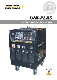
2.1 OPENING, LIFT AND WHEEL ASSEMBLY<br />
Open the box from the up side, take out the accessories from the box, take the screw-hook and scewit on the top of the machine.<br />
Lifting it by manual or mechanical elevator.<br />
The cart is designed for the mounting of two rotating front wheels and for the insertion of an axle for the fastening of the two<br />
fixed rear wheels.<br />
It is supplied with a kit comprising:<br />
Rotating front wheels, axle for the fixed rear wheels, rear wheels, bolts, split pins and cage nuts.<br />
Insert the cage nuts in the apposite slots as illustrated in pic. A and B.<br />
Mount the two front wheels as illustrated in pic. C.<br />
Insert the axle to fasten the rear wheels and block them with the split pins as illustrated in pic. D.
2.4 GAS BOTTLE INSTALLATION<br />
Put the gas bottle in vertical position on the gas bottle holder plane and position the bottle so that it is lays on the gas bottle<br />
holder and fix it with the chain and the spring clip, like in pic E.<br />
Tightly connect the gas hose, which comes from the back of the machine to the brass nipple of supplied regulator<br />
adjust argon regulator to deliver the required litres per minute.<br />
UNI FLAME AUTOLIFT<br />
NOTE. reffer to instruction manual of argon regulator for proper use.<br />
2.5 TORCH ASSEMBLY<br />
To connect the torch, you just have to insert it into the designed EURO adaptor on the front of the machine and then turn the<br />
collar tightly, like in pic.G. This way the electric connection as well as the gas connection is achieved.<br />
2.6 WIRE SPOOL HOUSING<br />
Put the wire spool on the paddle wheel and insert the wire in the wire feeder like in pic.H. The models can all hold either the 5<br />
Kg or the 15 Kg spool. The paddle wheel has a clutch designed to maintain the wire pulled.<br />
2.7 WIRE FEEDER MOTOR<br />
Make sure that the size of the groove in the wire feeding roll corresponds to the size of the welding wire being used.<br />
The machines are arranged with a feed roll for Ø 0,6 and 0, 8 wire. In case you want to use Ø 1 welding wire, ask for the<br />
suitable feeding roll. The feeding roll has the wire diameter stamped on its side.<br />
2.8 HOW TO INSERT THE WELDING WIRE<br />
Cut the first 10 cm of the wire making sure that there are no burrs or distortions at the cut end.<br />
Open the mobile arm of the wire feeder unscrewing the pressure screw of the arm pic. I.<br />
Insert the wire into the wire guide passing it through the feed roll’s groove and then reinsert the wire into the second<br />
alignement guide, like in pic. L. Make sure the wire lies in the feed roll’s groove in a natural line. Drop the pressure arm and<br />
adjust the pressure through the specially designed screw, like in pic M.<br />
The right pressure is the one that allows the even advancing of the wire.<br />
In case the wire should jam, the driving wheel must slip so that the the wire itself doesn’t tangle.<br />
In case the wire tends to unroll, you have to adjust the pressure through the designed screw so that the spool is always<br />
pulled, like in pic N. On the contrary, if the clucth causes an excessive friction and the driving wheel tends to slide, you have to<br />
decrease it until the wire advances evenly.<br />
3. SAFETY RULES<br />
Welding can be dangerous to both operator and bystanders. The following safety rules are strongly recommended.<br />
Personal cautions!<br />
Wear suitable clothing, possibly without protruding pockets and turn up and avoid synthetic materials.<br />
Always wear welding gloves.<br />
Wear heavy duty shoes, high laced with steel caps.<br />
Always use a welding mask fitted with a suitable dark lens, which have also a side protection.<br />
Caution: gas fumes!<br />
Ensure a good ventilation of the work area. If necessary, use an aspiration plant, above all in small working rooms.<br />
Clean away from the work piece any rust, grease or paint to reduce fumes as much as possible.<br />
Caution: short-circuit risk!<br />
Make sure the electric net is provided with adequate earthing and protection against overloads and short circuits.<br />
Make sure that all the main cables, torch, earth are in good conditions and replace if necessary.<br />
Connect the earth cable firmly to the workpiece.<br />
Do not wrap earth or torch cables around the body.<br />
Do not point the torch towards people.<br />
Avoid welding in wet or excessively damp conditions.<br />
Do not operate the machine with its side panels removed.<br />
Do not touch the contact tip on the torch or the workpiece.<br />
Caution: explosion risk!<br />
Do not weld in the proximity of inflammables.<br />
Ensure the welding machine is positioned on a flat, stable level.<br />
Tie the gas bottle to the machine with the chain provided, away from sources of heat.<br />
Make sure you are using the correct gas mixture and the gas reducer is of a proved type and that it works properly.<br />
Don’t use the machine for a tube defrosting activity.<br />
The machine has an IP 21 protection level - it is not to be used or stored in the rain!<br />
4. WELDING<br />
It’s possible to regulate the welding functions selecting the PCB’s electronic card options, located on the generator<br />
Switching the machine to position on, the display on the PCB show the last welding current measured.
UNI FLAME AUTOLIFT<br />
LEGENDA:<br />
Mod.A<br />
LEGENDA:<br />
Mod.B<br />
LED 1 = Thermal protection<br />
LED 2 = Trigger normal – Manual welding<br />
LED 3 = Trigger latch – Automatic welding<br />
LED 4 = Stich welding<br />
LED 5 = Spot welding<br />
S1 = Menù. To select welding parameter on the display<br />
S2 = Mode. To select welding type on the led welding parameter<br />
DISPLAY = Show welding parameter<br />
ENC = Encoder<br />
4.1 WELDING TYPE<br />
Pushing S2 (mode) it’s possible to select the type of welding<br />
needed on the led 2,3,4 and 5<br />
A) MANUAL (led2):<br />
Pushing the switch on the torch it is possible start to weld,<br />
releasing it shall stop the welding.<br />
B) AUTOMATIC (led3):.<br />
Pushing the switch on the torch it is possible to begin welding<br />
continuously, the switch must be pushed more time in order to<br />
stop the process.<br />
C) STICH WELDING (led4):<br />
Pushing the switch on the torch the machine weld for the<br />
selected time (Time on regulation as in 4.2.5), then will stop for<br />
the selected time (Pause time regulation as in 4.2.6). The<br />
machine will repeat automatically the cycle.<br />
D) SPOT WELDING (led5):<br />
Pushing the switch on the torch the machine weld for the<br />
selected time (Time on regulation as in 4.2.5), after this period it<br />
will stop. It is necessary to re-push the button in order to repeat<br />
the mentioned function.<br />
4.2 WELDING PARAMETER – Display<br />
Pushing S1 (menù) button it is possible to select the parameter<br />
used during the welding, increasing or decreasing the values<br />
using the knob of the encoder.<br />
LEGENDA:<br />
LED = Thermal protection<br />
S1 = Menù. To select welding parameter on the display<br />
DISPLAY = Show welding parameter<br />
ENC = Encoder<br />
4.1 WELDING TYPE<br />
A) MANUAL:<br />
Pushing the switch on the torch it is possible start to weld,<br />
releasing it shall stop the welding. (Time ON=0)<br />
D) SPOT WELDING:<br />
Pushing the switch on the torch the machine weld for the<br />
selected time (see 4.2.5 how to regulate it), after this period it will<br />
stop. It is necessary to re-push the button in order to repeat the<br />
mentioned cycle.<br />
4.2 WELDING PARAMETER – Display<br />
Pushing S1 (menù) button it is possible to select the parameter<br />
used during the welding, increasing or decreasing the values using<br />
the knob of the encoder<br />
LEGENDA:<br />
Don’t press the “MODE” button while you are welding.<br />
It is possible to reset the PCB’s original parameter (DEFAULT)<br />
following these steps:<br />
Turn off the welding machine, pushing the on/off switch<br />
(position 0). Push S1 and S2 button. Turn on the welding<br />
machine, keeping pushed for three seconds<br />
It is possible to reset the PCB’s original parameter (DEFAULT)<br />
following these steps:<br />
Turn off the welding machine, pushing the on/off switch<br />
(position 0). Push S1 button. Turn on the welding machine,<br />
keeping pushed for three seconds
1) Wire speed: It is possible to regulate the wire speed using the knobs of the encoder<br />
2) Pregas: It is possible to regulate the gas open time using the knob of the encoder before<br />
the arc prime<br />
3) Ramp up: It is possible to regulate the wire increasing gradually using the knobs of the<br />
encoder in order to have the one selected at point 4.2.1<br />
UNI FLAME AUTOLIFT<br />
4) Burn back: it is possible to regulate, using the knob of the encoder, the wire length came<br />
out at the end of welding process.<br />
5) Time on: it is possible to regulate, using the knob of the encoder, the welding time for the<br />
welding type 4.1.C and 4.1.D. (Only Mod.B) Regulating it on 0 (zero) value, the welding<br />
is set on manual (4.1.A)<br />
6) Pause time: it is possible to regulate, using the knob of the encoder, the pause time for<br />
the welding type 4.1.C<br />
7) Thermal overload: show the thermal overload goes on, it is necessary to wait for<br />
machine cooling. The sign disappear after a few seconds. The thermal overload restoring<br />
is shown when the led 1 switch off.<br />
4.3 GAS PRESSURE<br />
Gas pressure should normally be set to give a reading between 8 / 15 litres per minute. With experience, every operator will<br />
find what suits him the most with his type of work and can make the necessary adjustment.<br />
4.4 GAS-NO GAS WELDING<br />
When you gas with wire, gas is needed for the protection of the melt dip. Usually, the gas to be used is a mix of Argon and CO2,<br />
pure Argon or pure CO2. The argon one is employed for the welding of aluminium while other are used for the welding of ferrous<br />
material.<br />
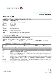
In case of use with gas, the clip of the torch has to be placed in the positive outlet “+”, while the earth clamp has to be placed in<br />
the negative outlet “-“, like in pic. O.<br />
The use of gas can be avoided if you use flux cored wire. This kind of wire emits gas which creates a protective environment<br />
for the welding. In case you want to weld with flux cored wire, place the torch clip in the negative outlet “-“, and the earth clamp<br />
in the positive outlet “+”, like in pic.P<br />
4.5 DOUBLE INDUCTANCE (Unimig 240)<br />
If you need a lowest inductance to use the machine for a bigger power, put the dinse connector in the<br />
exit<br />
4.6 MIG-MAG WELDING<br />
A) MIG = Metal Inert Gas<br />
B) MAG = Metal Active Gas<br />
The two processes are exactly the same, only gas used changes.<br />
In case A ARGON is the gas employed ( inert gas)<br />
In case B CO 2<br />
is the gas employed ( active gas)<br />
To weld alluminium alloys you need use ARGON (100%), to weld steel it is enough a compound of ARGON 80% and CO2<br />
20%.<br />
You can only use pure CO2 in case you want to weld iron.
UNI FLAME AUTOLIFT<br />
WELDING GUIDE<br />
GENERAL RULE<br />
When welding on the lowest output settings, it is necessary to keep the arc as short as possible.<br />
This should be achieved by holding welding torch as close as possible and at an angle of approximately 60 degrees to the<br />
workpiece. The arc length can be increased when welding on the highest settings, an arc length up to 20 mm can be enough<br />
when welding on maximum settings.<br />
GENERAL WELDING TIPS<br />
From time to time, some faults may be observed in the weld owing to external influences rather due to welding machinès faults.<br />
Here are some that you may come across :<br />
· Porosity<br />
Small holes in the weld, caused by break-down in gas coverage of the weld or sometimes by foreign bodies inclusion. Remedy<br />
is, usually, to grind out the weld.<br />
Remember, check before the gas flux (about 8 liters/minutes), clean well the working place and finally incline the torch while<br />
welding.<br />
· Spatter<br />
Small balls of molten metal which come out of the arc. A little quantity is unavoidable, but it should be kept down to a minimum<br />
by selecting correct settings and having a correct gas flow and by keeping the welding torch clean.<br />
· Narrow heap welding<br />
Can be caused by moving the torch too fast or by an incorrect gas flow.<br />
· Very thick or wide welding<br />
Can be caused by moving the torch too slowly.<br />
· Wire burns back<br />
It can be caused by wire feed slipping, loose or damaged welding tip, poor wire, nozzle held too close to work or voltage too high.<br />
· Poor penetration<br />
It can be caused by moving torch too fast, too low voltage setting or incorrect feed setting, reversed polarity, insufficient blunting<br />
and distance between strips. Take care of operational parameters adjustment and improve the preparation of the workpieces.<br />
· Workpiecès piercing<br />
It may be caused by moving the welding torch too slow, too high welding power or by an invalid wire feeding.<br />
· Heavy spatter and porosity<br />
Can be caused by nozzle too far from work, dirt on work or by low gas flow. You have to the two parameters, remeber that<br />
gas has not to be lower than 7-8 liters/min. and that the current of welding is appropriated to the wire you are using. It is<br />
advisable to have a pressure reducer of input and output. On the manometer you can read the range expressed in liter.<br />
· Welding arc instability<br />
It may be caused by an insufficient welding voltage, irregular wire feed, insufficient protective welding gas.<br />
FAULT FINDING<br />
FAULT REASON REMEDY<br />
Wire isn’t conveyed when 1) Dirt in liner and/or contact tip Blow with compressed air,<br />
feed roll is turning<br />
replace contact tip<br />
2) The friction brake in the hub Loosen<br />
is too tightened<br />
3) Faulty welding torch Check sheating of torchès<br />
wire guide<br />
Wire feeding in jerk or 1) Contact tip defect Replace<br />
erratic way 2) Burns in contact tip Replace<br />
3) Dirt in feed roll groove Clean<br />
4) Feed roll’s groove worn Replace<br />
No arc 1) Bad contact between earth clamp Tighten earth clamp and<br />
and workpiece<br />
check connections<br />
2) Short-circuit between contact tip Clean, replace tip and/or<br />
and gas shroud<br />
shroud as necessary<br />
Porous welding seams 1) Failre of gas shield owing Clean gas shroud from<br />
to spatters in gas shro<br />
spatters<br />
2) Wrong welding torch distance The lenght of stick out wire<br />
and/or inclination from workpiece<br />
from tip must be 5-10 mm.<br />
Inclination not less than 60<br />
degrees in relation to<br />
workpiece<br />
3) Too small gas flux Increase flux of welding<br />
gas<br />
4) Humid workpieces Dry with heat producer<br />
5) Heavily rusted workpieces Clean workpieces from rust<br />
The machine suddenly stops 1) Welding machine overheated Don’t switch off the machine,<br />
weldig operations after an due to an excessive use in stated let it cool down for about<br />
extended and heavy duty duty cycle 20/30 minutes<br />
use<br />
The machine is switch off even Fuse blowed on the service transformer Replace<br />
it is
DESCRIPTION OF GRAPHICS<br />
UNI FLAME AUTOLIFT
UNI FLAME AUTOLIFT<br />
A B C<br />
D E F<br />
G H I<br />
L M N
UNI FLAME AUTOLIFT<br />
O<br />
P
CAUTION<br />
UNI FLAME AUTOLIFT<br />
1. Working Environment.<br />
1.1 The environment in which this welding equipment is installed must be<br />
free of grinding dust, corrosive chemicals, flammable gas or materials etc, and at<br />
no more than maximum of 80% humidity.<br />
1.2 When using the machine outdoors protect the machine from direct sun light, rain<br />
water and snow etc; the temperature of working environment should be<br />
maintained within -10°C to +40°C.<br />
1.3 Keep this equipment 30cm distant from the wall for ventilation.<br />
1.4 Ensure the working environment is well ventilated.<br />
2. Safety Tips.<br />
2.1 Ventilation<br />
This equipment is small-sized, compact in structure, and of excellent performance<br />
in amperage output. The fan is used to dissipate heat generated by this<br />
equipment during the welding operation.<br />
Important:<br />
Maintain good ventilation of the louvers of this equipment. The minimum distance<br />
between this equipment and any other objects in or near the working area should<br />
be 30 cm. Good ventilation is of critical importance for the normal performance<br />
and service life of this equipment.<br />
2.2 Thermal Overload protection.<br />
Should the machine be used to an excessive level, or in high temperature<br />
environment, poorly ventilated area or if the fan malfunctions the Thermal Over<br />
load Switch will be activated and the machine will cease to operate. Under this<br />
circumstance, leave the machine switched on to keep the built-in fan working to<br />
bring down the temperature inside the equipment. The machine will be ready for<br />
use again when the internal temperature reaches safe level.<br />
2.3 Over-Voltage Supply<br />
Regarding the power supply voltage range of the machine, please refer to “Main<br />
parameter” table. This equipment is of automatic voltage compensation, which<br />
enables the maintaining of the voltage range within the given range. In case that<br />
the voltage of input power supply amperage exceeds the stipulated value, it is<br />
possible to cause damage to the components of this equipment. Please ensure<br />
your primary power supply is correct.<br />
2.4 Do not come into contact with the output terminals while the machine is in<br />
operation. An electric shock may possibly occur.
MAINTENANCE<br />
WARNING:<br />
Exposure to extremely dusty, damp, or corrosive air is damaging to the welding<br />
machine. In order to prevent any possible failure or fault of this welding<br />
equipment, clean the dust at regular intervals with clean and dry compressed air<br />
of required pressure.<br />
Please note that: lack of maintenance can result in the cancellation of the<br />
guarantee; the guarantee of this welding equipment will be void if the machine<br />
has been modified, attempt to take apart the machine or open the factory-made<br />
sealing of the machine without the consent of an authorized representative of the<br />
manufacturer.<br />
TROUBLESHOOTING<br />
Caution:<br />
Only qualified technicians are authorized to undertake the repair of this welding equipment.<br />
For your safety and to avoid Electrical Shock, please observe all safety notes<br />
and precautions detailed in this manual.<br />
WARRANTY<br />
• 3 Years from date of purchase.<br />
• Welding Guns of Australia Pty Ltd warranties all goods as specified by the<br />
manufacturer of those goods. This Warranty does not cover freight or goods that have<br />
been interfered with. All goods in question must be repaired by an authorised repair agent<br />
as appointed by this company. Warranty does not cover abuse, mis-use, accident, theft,<br />
general wear and tear. New product will not be supplied until<br />
Welding Guns of Australia Pty Ltd has inspected product returned for warranty<br />
and agree’s to replace product. Product will only be replaced if repair is impossible.<br />
If in doubt please ring.<br />
WELDING GUNS OF AUSTRALIA Pty Ltd<br />
WWW.UNIMIG.COM.AU<br />
Disclaimer:<br />
While the information is provided in good faith, Welding Guns Of Australia does not warrant the accuracy of information<br />
provided nor assume any legal responsibility for it or for any damage which may result from reliance on or use of it or from any<br />
negligence of Welding Guns Of Australia or other person/s with respect to it.<br />
For further information please call Welding Guns of Australia Pty Ltd.<br />
112 Christina Rd, Villawood NSW 2163 - PO Box 3033 Lansvale NSW 2166<br />
UNIMIG pursue a policy of continuous research and development, and therefore<br />
reserve the right to change the specifications, or design, without prior notice. *<br />
3 year warranty power source.


![Weldmatic 175 [internal wirefeeder] - BJH](https://img.yumpu.com/48683580/1/184x260/weldmatic-175-internal-wirefeeder-bjh.jpg?quality=85)