rtf model - CML Distribution
rtf model - CML Distribution
rtf model - CML Distribution

You also want an ePaper? Increase the reach of your titles
YUMPU automatically turns print PDFs into web optimized ePapers that Google loves.
F-4E Phantom<br />
RTF MODEL<br />
Congratulations on purchasing the Top Gun F-4E Phantom RTF<br />
INSTRUCTION MANUAL<br />
Top Gun Park Flite are proud to present this high performance<br />
ducted fan sport scale <strong>model</strong> of the F4 Phantom. Supplied in<br />
three versions, TGP0200 is a Ready to Fly package with<br />
transmitter, receiver, LiPo flight battery and charger, TGP0201 is<br />
an Almost Ready to Fly package without transmitter and<br />
receiver and TGP0202 is an Airframe only with ducted fan and<br />
motor.<br />
This <strong>model</strong> has been designed with the utmost care and<br />
attention to detail to produce a light weight, strong, and<br />
realistic looking <strong>model</strong> aeroplane with excellent flying<br />
characteristics.<br />
We feel that this <strong>model</strong> emulates the style, performance and<br />
character of its full size counterpart.<br />
This <strong>model</strong> is a high performance miniature aircraft that allows<br />
intermediate to advanced <strong>model</strong> pilots to perform both scale<br />
and aerobatic manoeuvers. The light weight, large wing area<br />
and powerful ducted fan motor assembly allow the <strong>model</strong> to fly<br />
both fast and slow, with high speed rolls and tight turns while<br />
maintaining full control.<br />
These instructions assume a reasonable level of competence<br />
for both building and flying and we recommend that the <strong>model</strong><br />
is flown at a recognised club with frequency control measures<br />
and suitable third party insurance.<br />
The owner – pilot of this <strong>model</strong> should take note of regulations,<br />
and local bylaws before flying this aircraft.<br />
Please take time to read through these instructions before<br />
commencing assembly. We list operations in order of works to<br />
reduce the risk of damage during assembly.<br />
PLEASE READ THROUGH ALL WARNINGS AND<br />
GUIDELINES FOR LIPO HANDLING AT THE<br />
BACK OF THE MANUAL BEFORE USE.<br />
An 11.1V 1300 mAh lithium polymer (LiPo) battery and charger<br />
is included as part of this package and these cells must be<br />
operated with care to prevent the risk of fire.<br />
LiPo Batteries are soft cased and can be easily damaged by<br />
sharp items, puncturing of the soft casing can cause fires and<br />
we recommend that they are stored and handled carefully.<br />
Use only a LiPo rated charger, set to a maximum of 3 cells<br />
(11.1v) and no more than 1 amp charge current.<br />
Remove battery from the aircraft and charge on a non<br />
flammable, non conductive surface<br />
Due to continual and ongoing product development the parts<br />
shown in the manual may differ from those supplied.<br />
2
KIT CONTENTS AND DESCRIPTION (DEPENDANT ON VERSION)<br />
(RTF contents pictured)<br />
1. Fuselage with ducted fan, motor, Electronic<br />
Speed Control (ESC) receiver, elevator servo<br />
and steering servo with pushrods.<br />
2. Fuselage nosecone section<br />
3. Clear cockpit canopy.<br />
4. Two wing panels with factory hinged ailerons<br />
and aileron servos installed<br />
5. Two horizontal stabiliser panels<br />
6. Elevator joiner assembly.<br />
7. Vertical stabiliser-fin<br />
8. Main undercarriage and nose gear assemblies<br />
with wheels and mounting hardware<br />
9. Four function fully proportional 35Mhz<br />
transmitter<br />
10. Pushrods, control horns, linkage and fixing<br />
hardware<br />
11. Tube of adhesive<br />
12. LiPo Battery 3 cell 11.1V 1300 mAh (15c)<br />
13. Mains power 3 cell LiPo charger<br />
14. Self adhesive decals.<br />
SPECIFICATIONS<br />
Specifications<br />
Wing span 542mm (21.34”)<br />
Length 788mm (31”)<br />
Wing Area 8Dm_ (124 sq inches)<br />
Weight<br />
Radio<br />
Motor<br />
WARNING<br />
540 g (19 Ounces)<br />
4 function 35Mhz PPM<br />
4 Qty micro servos<br />
25 Amp brushless ESC<br />
Brushless in runner<br />
5 blade 64mm ducted fan<br />
11.1v 1300mAh LiPo battery<br />
This R/C aircraft is not a toy and can<br />
result in serious bodily harm, injury and<br />
property damage if misused.<br />
Fly only in open areas and at preferably<br />
BMFA recognised clubs and sites.<br />
3
SECTION 1: KIT CONTENTS AND DESCRIPTION<br />
MAIN FUSELAGE ASSEMBLY.<br />
Supplied complete with ducted<br />
fan unit using high performance<br />
brushless in runner motor.<br />
25Amp Electronic Speed Control<br />
(ESC) pre-wired to motor with<br />
extended leads to forward<br />
battery box and hinged cover.<br />
35mhz 6 channel receiver<br />
installed inside hidden<br />
compartment and pre-wired to<br />
aileron, steering and elevator<br />
servo.<br />
Built in grip for hand launching.<br />
Nose Cone<br />
Clear vacuum formed canopy<br />
Wing Panels, supplied as two<br />
halves.<br />
Each wing half includes factory<br />
hinged aileron pre-drilled ready<br />
to receive control horn.<br />
Wing underside has<br />
undercarriage fixing plate and<br />
factory fitted aileron servo.<br />
4
Two horizontal stabiliser panels pre-drilled ready to<br />
receive control horn.<br />
Main Undercarriage and nose gear units.<br />
Two sets of lightweight wheels fixed onto wire<br />
torque rod undercarriage.<br />
Four clamp plates and 8 fixing screws for securing<br />
to wing plates.<br />
Nose gear steering arm is factory installed in<br />
Note left and right panels are identified by joiner<br />
recess on lower face only.<br />
Horizontal stabiliser joiners with fixing screws.<br />
Control horn with clamp connector, backplate and<br />
fixing screws<br />
Elevator push rod.<br />
fuselage.4 function fully proportional 35Mhz<br />
transmitter.<br />
Vertical stabiliser-fin.<br />
Available on 5 alternate 35 MHz frequencies.<br />
5
Aileron pushrods, control horns, and fixing<br />
hardware.<br />
Two short pushrods with clevis connector.<br />
ADHESIVE<br />
5ml tube of foam safe adhesive.<br />
Note pierce end of tube with pin in screw on lid.<br />
Two Control horns with back plates and four fixing<br />
screws.<br />
SECTION 2: BATTERY AND CHARGER<br />
BATTERY AND CHARGER<br />
WARNING<br />
(items may differ from<br />
contents)<br />
BATTERY AND CHARGER<br />
11.1V (3 cell) 1300mAh (C) LiPo Battery rated at<br />
15C max discharge. Fitted with 3.5mm gold plug<br />
and socket.<br />
12v Lipo Balance charger. Easy to use automatic<br />
Lithium Polymer charger for 2-3 cell packs.<br />
A lithium polymer (LiPo) battery rated at 15C<br />
(19.5A) discharge and fast charger is included<br />
as part of this package, these cells must be<br />
operated with care to prevent the risk of fire.<br />
LiPo Batteries are soft cased and can be easily<br />
damaged by sharp items, puncturing of the soft<br />
casing can cause fires and we recommend that<br />
they are stored and handled carefully.<br />
Use only the supplied balance charger or a LiPo<br />
rated charger set to a maximum of 3 cells<br />
(11.1v) and less than 1 amp charge current.<br />
Remove battery from the aircraft and charge on<br />
a non flammable, non conductive surface<br />
6
SECTION 3: TRANSMITTER<br />
The FM4DP is a fully proportional 4 function 35Mhz<br />
transmitter.<br />
The kit includes a high performance 11.1V (3 cell)<br />
1300mAh LiPo Battery rated at 20C (19.5 amp) max<br />
discharge.<br />
The kit includes a high performance 11.1V (3 cell)<br />
1300mAh LiPo Battery rated at 20C (19.5 amp) max<br />
discharge.<br />
This must be charged using the dedicated 12v DC<br />
input 0.8 Amp output fast charger and connecting<br />
lead.<br />
Connect the crocodile lead connectors to a 12V DC<br />
power source (a 12V car battery is ideal), ensuring<br />
that correct polarity is observed. Red is positive (+)<br />
and Black is Negative (-).<br />
Connect the lead into the matching socket of the<br />
battery charger and the Red LED will illuminate.<br />
Push the white balance plug of the battery into the<br />
matching charger output socket to commence<br />
charging.<br />
The green LED illuminates to confirm charging and<br />
switches off when the charge is complete<br />
A full charge will take between 1 and 2 hours.<br />
The transmitter is supplied in a Mode 2<br />
configuration. Mode 2 is also known as Throttle<br />
Left.<br />
The left stick controls Throttle and rudder<br />
movement.<br />
The right stick controls aileron and elevator<br />
movement.<br />
Battery state is indicated by a green and red bank<br />
of coloured LED.<br />
A flashing red LED and audible alarm indicates<br />
dangerously low voltage. The <strong>model</strong> should be<br />
landed immediately to replace batteries before all<br />
control is lost.<br />
Frequency control is by removable crystal, The<br />
transmitter frequency is identified on the crystal<br />
holder located on the front of the transmitter.<br />
CHARGE IN A TIN AND AWAY FROM COMBUSTABLE<br />
MATERIAL. DO NOT CHARGE UNATTENDED. GO TO<br />
REAR OF MANUAL FOR FURTHER GUIDES<br />
7
8 off AA size dry cells or high capacity Nimh<br />
batteries (not included) must be inserted before<br />
operation.<br />
Remove the rear cover and install batteries into the<br />
battery tray as directed by the moulded in polarity<br />
(+ & -) markings.<br />
A small panel of four small slide switches is set on<br />
the front panel of the transmitter.<br />
These are electronic servo reversing switches and<br />
should be adjusted to give the correct control<br />
surface deflections relative to stick movements.<br />
SECTION 4: ASSEMBLY<br />
Locate the main fuselage assembly and nose cone<br />
and dry fit together ensuring that the parts locate<br />
together.<br />
Insert undercarriage into mounting plate located in<br />
the wing panels and fix in place with saddles and<br />
four self tapping screws.<br />
Note wheel is located outwards towards rear of the<br />
wing.<br />
Position the nose wheel assembly over the collet in<br />
the forward fuselage.<br />
The flat machined in the wire should align with the<br />
grub screw with the coil facing forward.<br />
Insert wire in collet and tighten grub screw with<br />
Allen key.<br />
Apply adhesive to the contact faces and press firmly<br />
together<br />
Wipe off any excess adhesive and allow to dry.<br />
Locate the main undercarriage assemblies, clamp<br />
plates and fixing screws.<br />
8
Locate the control horns and fixings.<br />
Position the control horn over the recess moulded in<br />
the aileron<br />
Ensure that horn is on the bottom surface and apply<br />
a drop of adhesive before pressing in place.<br />
Fix in place with two screws and backplate.<br />
Locate the aileron pushrods<br />
Locate the two horizontal stabiliser panels, elevator<br />
joiners and fixing screws.<br />
Position the joiners the recess moulded in the<br />
elevator panels. The spikes will key into the foam.<br />
Ensure that joiner is on the bottom surface of both<br />
panels and apply adhesive before pressing in place.<br />
Wipe off excess adhesive and allow to dry before<br />
proceeding further.<br />
Connect Z-bend of short pushrod to outer hole of<br />
servo arm.<br />
Clip clevis connector into hole in horn furthest from<br />
aileron surface.<br />
Locate the vertical stabiliser-Fin and test fit onto<br />
rear of fuselage.<br />
Apply adhesive to the contact faces and press firmly<br />
together and use pins or tape to hold in place.<br />
Wipe off any excess adhesive and allow to dry.<br />
9
Remove excess length of pushrod with wire<br />
cutters.<br />
Test fit the two horizontal stabiliser panels.<br />
The joiners pass through a tube at the rear of the<br />
fuselage.<br />
The panels should be angled downwards. (anhedral)<br />
Fit the two fixing screws to lock the joiner in place.<br />
Test fit the two wing panels on to the fuselage<br />
Apply adhesive to the contact faces on the wing and<br />
fuselage and press firmly together use pins or tape<br />
to hold in place.<br />
Wipe off any excess adhesive and allow to dry.<br />
Repeat procedure for the other wing panel.<br />
SECTION 5: FINAL SET UP<br />
Locate the elevator pushrod, control horn, fixings<br />
and backplate.<br />
position the control horn on the moulded recess on<br />
the elevator in line with the servo arm and fix in<br />
place with screws and backplate.<br />
Insert the pushrod through the clamp connectors in<br />
the servo arm and control horn.<br />
WARNING<br />
With the battery connected and the <strong>model</strong><br />
switched on the motor is live. The Electronic<br />
speed controller (ESC) will go through its start<br />
up procedure and will emit a series of beeps<br />
while it configures throttle positions. The<br />
motor could start unexpectedly and we<br />
recommend that the <strong>model</strong> is restrained during<br />
handling.<br />
Ensure that transmitter is switched on with throttle<br />
down and all trims central.<br />
Open the hinged battery bay door by turning the<br />
catches.<br />
Insert into the battery and ensure that battery and<br />
ESC leads project out of the aperture.<br />
Connect the battery and ESC leads together<br />
Red-red and Black-Black and close the battery<br />
cover using the catches to lock it in place.<br />
Align elevators with mould line in fuselage and<br />
gently tighten connectors until the controls are<br />
checked.<br />
Uncoil the receiver aerial and fully extend to hang<br />
off the rear of the aircraft.<br />
10
Adjust aileron surfaces if required by unclipping the<br />
pushrod clevis connectors and winding in or out to<br />
suit.<br />
The steering servo and elevators can also be<br />
adjusted on the clamp connectors.<br />
Ensure that trims and sticks are central, loosen<br />
clamp screw and tighten down firmly when<br />
centralized.<br />
Run the aircraft along a smooth surface to confirm<br />
the steering is central.<br />
When happy with the nose wheel alignment apply a<br />
few drops of adhesive around the canopy frame and<br />
press in place. 5.3<br />
CHECK THE BALANCE.<br />
Check that all controls operate in the correct<br />
manner and that all control surfaces are level.<br />
The <strong>model</strong> should sit level or slightly nose down<br />
when supported upside down from a point 85mm<br />
back from the point where the wing leading edge<br />
joins the fuselage. This corresponds to a point<br />
midway along the top surface air brakes panel line.<br />
DO NOT ATTEMPT TO FLY WITH A REARWARD<br />
BALANCE POINT<br />
85mm<br />
11
SECTION 6: FIRST FLIGHT<br />
BEFORE THE TEST FLIGHT<br />
On completion of the <strong>model</strong> take time to test the<br />
<strong>model</strong> in the workshop.<br />
Switch on the transmitter,<br />
connect the battery and<br />
double check that all<br />
surfaces operate in the<br />
correct manner without<br />
stalled servos.<br />
Check for adequate range<br />
with and without motor<br />
running.<br />
If everything is okay, take it to the flying field and<br />
rig it up again.<br />
Always follow the frequency control procedures of<br />
your local flying site and ensure that you have<br />
adequate third party insurance cover.<br />
Repeat the full pre flight inspection before flying.<br />
12<br />
FLYING<br />
WARNING<br />
Do not advance the throttle unless the <strong>model</strong> is<br />
restrained. With the powerful motor-fan<br />
combination producing up to 500g of thrust, the<br />
<strong>model</strong> will accelerate across a smooth surface<br />
very quickly.<br />
The F4 Phantom is capable of 5 to 10 minute flight<br />
times and can R.O.G (Rise Off Ground) from smooth<br />
metalled runways or very closely cut grass. A hand<br />
launch will be required If flying from normal grass<br />
or without undercarriage. .<br />
It is aerobatic and able to<br />
perform loops and rolls<br />
but due to its light weight<br />
it should not be flown in<br />
wind greater than 10mph.<br />
Control throws set during<br />
assembly will produce a<br />
<strong>model</strong> capable of flying<br />
smooth scale like performance and medium to high<br />
speed aerobatic manoeuvers.<br />
The control surface movements can be increased by<br />
moving the clevis connectors nearer to the control<br />
surfaces.<br />
To reduce movements move the pushrod<br />
connections nearer to the servo on the output arms<br />
and further out along the control surfaces horns.<br />
ENJOY YOURSELF BUT ALWAYS FLY SAFE!
ADDENDUM<br />
REMOVAL OF UNDERCARRIAGE<br />
For an improved in flight performance and<br />
appearance the tricycle undercarriage can be<br />
removed.<br />
Removal of the undercarriage assemblies reduces<br />
both the weight and drag of the <strong>model</strong> increasing<br />
the power to weight ratio and top speed, the wing<br />
loading also drops slightly which improves<br />
manoeuvrability.<br />
The decision should not be taken lightly though.<br />
Without an undercarriage the <strong>model</strong> must be hand<br />
launched firmly into wind and belly landings will be<br />
the norm.<br />
While the aircraft can be built without<br />
undercarriage, we recommend that the <strong>model</strong> is<br />
assembled and flown with wheels initially to allow<br />
time to familiarise with the aircrafts performance.<br />
While the main wheels and nose gear can easily be<br />
removed and replaced, removal of the nose wheel<br />
steering servo requires ‘minor surgery’.<br />
Removal of the main gears is a simple task<br />
involving removal of the fixing screws, clamp plates<br />
and formed undercarriage assemblies. Similarly the<br />
nose wheel is removed by removing the grubscrew<br />
and pulling the wire out of the collet.<br />
To remove the steering servo slide a thin <strong>model</strong>ling<br />
blade between the canopy and fuselage to break the<br />
glue joints and remove the canopy<br />
Disconnect the nose gear steering servo from the<br />
receiver.<br />
Disconnect the steering push rod and slide a thin<br />
<strong>model</strong>ling blade between the servo and fuselage to<br />
break the glue joints. Remove the servo<br />
Refit the canopy with a few drops of adhesive.<br />
With the main wheels removed the moulded in grip<br />
beneath the fuselage provides an ideal finger and<br />
thumb hold for hand launching.<br />
13
IMPORTANT SAFETY INSTRUCTIONS AND WARNINGS – READ BEFORE USE<br />
• Lithium Polymer batteries can be volatile. Whilst some of the instances listed below are rare, they can occur and it is<br />
important for you to be aware of how to handle such situations. Failure to read and follow the below instructions may<br />
result in fire, personal injury and damage to property if charged or used improperly.<br />
• Top Gun Park Flite, its distributors or retailers assume no liability for failures to comply with these warnings and safety<br />
guidelines.<br />
• By using this battery, the buyer assumes all risks associated with lithium batteries. If you do not agree with these<br />
conditions, return the battery immediately before use.<br />
• The final use and preparation of the battery pack is ultimately beyond our control and those of our representatives and<br />
retaillers. Your decision to use this product incorporates your agreement that you have read and understood the safety<br />
precautions listed below and on each battery pack, and that you agree to accept full responsibility for any injury, loss or<br />
damage resulting from all circumstances surrounding your use or misuse of this product.<br />
GENERAL GUIDELINES AND WARNINGS<br />
1) Only use the supplied specific Lithium Polymer charger. Do not use a NiMH or NiCd charger - Failure to do so may a cause fire, which<br />
may result in personal injury and property damage.<br />
2) Never charge batteries unattended. When charging LiPo batteries you should always remain in constant observation to monitor the<br />
charging process and react to potential problems that may occur.<br />
4) If at any time you witness a battery starting to balloon or swell up, discontinue charging process immediately, disconnect the battery<br />
and observe it in a safe place for approximately 15 minutes. This may cause the battery to leak, and the reaction with air may cause the<br />
chemicals to ignite, resulting in fire.<br />
5) Since delayed chemical reaction can occur, it is best to observe the battery as a safety precaution. Battery observation should occur in a<br />
safe area outside of any building or vehicle and away from any combustible material.<br />
6) Wire lead shorts can cause fire! If you accidentally short the wires, the battery must be placed in a safe area for observation for<br />
approximately 15 minutes. Additionally, if a short occurs and contact is made with metal (such as rings on your hand), severe injuries<br />
may occur due to the conductibility of electric current.<br />
7) A battery can still ignite even after 10 minutes.<br />
8) In the event of a crash, you must remove battery for observation and place in a safe open area away from any combustible material for<br />
approximately 15 minutes.<br />
11) Never store or charge battery pack inside your car in extreme temperatures, since extreme temperature could ignite fire.<br />
CHARGING PROCESS<br />
1) Never charge batteries unattended.<br />
2) Charge in an isolated area, away from any flammable materials and inside a closed tin or lipo charge sack. In the unlikely event that the<br />
battery may fail and ignite, this procedure will ensure that a possible battery fire is contained and limiting any possible damage.<br />
3) Let battery cool down to ambient temperature before charging.<br />
DISCHARGE<br />
Ensure that you adhere to the warning beeps on your transmitter and land the <strong>model</strong> accordingly. Do not fly until the battery is completely<br />
discharged as damage will occur.<br />
STORAGE & TRANSPORTATION<br />
1) Store battery at room temperature between 40 and 80 degrees F for best results.<br />
2) Do not expose battery pack to direct sunlight (heat) for extended periods.<br />
3) When transporting or temporarily storing in a vehicle, temperature range should be greater than 20 degrees F but no more than 150<br />
degrees F.<br />
4) Storing battery at temperatures greater than 170 degrees F for extended periods of time (more than 2 hours) may cause damage to<br />
battery and possible fire.<br />
BATTERY LIFE<br />
Batteries that lose 20% of their capacity must be removed from service and disposed of properly. Discharge the battery to 3V/Cell, making sure<br />
output wires are insulated, then wrap battery in a bag for disposal.<br />
PRODUCT WARRANTY<br />
Product warranty is limited to original defects in material and workmanship. Warranty does not cover collateral damage. Due to the nature and<br />
use of the battery there is no term warranty. Misuse, abuse, incorrect charging and other inappropriate use of this product are not covered<br />
under warranty.<br />
14
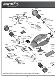
TOP GUN PARKFLITE F4 PHANTOM SPARE PARTS LIST<br />
TGP0200B F4E BLUE READY-TO-FLY EDF JET<br />
TGP0200M F4E MILITARY READY-TO-FLY EDF JET<br />
TGP0201B F4E BLUE ARTF EDF JET (NO TX/RX)<br />
TGP0201M F4E MILITARY ARTF EDF JET(NOTX/RX)<br />
TGP0202B F4E BLUE AIRFRAME ONLY EDF JET<br />
TGP0202M F4E MILITARY AIRFRAME ONLY EDF JET<br />
TGP0205B F-4E FUSELAGE (BLUE/YELL)<br />
TGP0205M F-4E FUSELAGE (MILITARY)<br />
TGP0206B F-4E WING SET (BLUE/YELL)<br />
TGP0206M F-4E WING SET (MILIATRY)<br />
TGP0207B F-4E VERTICAL WING SET (BLUE/YELL)<br />
TGP0207M F-4E VERTICAL WING SET (MILITARY)<br />
TGP0208B F-4E TAIL WING SET (BLUE/YELL)<br />
TGP0208M F-4E TAIL WING SET (MILITARY)<br />
TGP0209B F-4E PVC PARTS (BLUE/YELL)<br />
TGP0209M F-4E PVC PARTS (MILITARY)<br />
TGP0210 F-4E CONTROL ROD & PLASTIC PARTS<br />
TGP0211 F-4E LANDING GEAR<br />
TGP0512 TRANSMITTER<br />
TGP0532 INRUNNER MOTOR<br />
TGP0527 1300mah 20c 3S LIPO<br />
TGP0092 65MM DUCTED FAN UNIT<br />
TGE0001 ETRONIX 8.4G SERVO<br />
TGE0051 ETRONIX 25AMP SPEED CONTROL<br />
DISTRIBUTORS OF QUALITY MODEL & HOBBY PRODUCTS<br />
Saxon House, Saxon Business Park, Hanbury Road, Bromsgrove, Worcestershire. B60 4AD. England<br />
Tel: +44 (0) 1527 575349 Fax: + 44 (0) 1527 570536<br />
E-mail: info@cmldistribution.co.uk<br />
Web site: www.cmldistribution.co.uk<br />
15