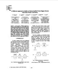
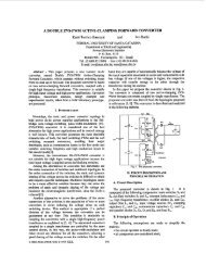
A Three-Phase Buck Rectifier with High-Frequency Isolation - Ivo Barbi
A Three-Phase Buck Rectifier with High-Frequency Isolation - Ivo Barbi
A Three-Phase Buck Rectifier with High-Frequency Isolation - Ivo Barbi

Create successful ePaper yourself
Turn your PDF publications into a flip-book with our unique Google optimized e-Paper software.
C v (z) =0, 0276 ·<br />
z − 0, 983<br />
z − 1<br />
(12)<br />
VI. EXPERIMENTAL RESULTS<br />
Operation and performance of designed prototype are illustrated<br />
by the following experimental results obtained at load<br />
resistance of 0.89Ω exceeding the designed power of 2.5kW.<br />
The Fig.9 shows an input reference phase voltage and input<br />
current, which is perceived the quality for the input current<br />
in phase <strong>with</strong> the voltage. Fig.10 shows the three-phase input<br />
currents where phase a presents low distortion, phase b and c<br />
are almost sinusoidal. The input capacitor voltage and current<br />
are illustrated at Fig.11 where the current carries the high<br />
frequency harmonics generated by PWM <strong>Buck</strong> rectifier bridge<br />
<strong>with</strong> relevant peak current that shall be consider when chosen<br />
the capacitor.<br />
Fig. 11.<br />
Input capacitor voltage an current.<br />
and the measured efficiency at four different values of load<br />
resistance at dotted line. The overall efficiency at full load is<br />
around 80%.<br />
Fig. 9.<br />
<strong>Phase</strong> voltage and current.<br />
Fig. 12.<br />
Switch voltage and current.<br />
Fig. 13.<br />
Secondary voltage and current.<br />
Fig. 10.<br />
Input currents.<br />
Fig.12 shows the voltage and current in a power switch,<br />
upper is a view at low frequency and below is the expanded<br />
view <strong>with</strong> voltage and current follow the safety and expected<br />
behavior performed by the snubber assistance. Fig.13 shows<br />
the secondary winding voltage and current as well as the<br />
demagnetization current. Fig.14 shows the load voltage and<br />
current at steady state and the Fig.15 shows the soft-start<br />
achieved <strong>with</strong>out auxiliary circuits for the prototype. The<br />
power quality is proved in the Fig.16 <strong>with</strong> a total harmonic<br />
distortion of 6.4% and power factor of 0.998 both to phase a.<br />
Fig.17 shows the estimated prototype efficiency at bold line<br />
VII. CONCLUSION<br />
A prototype design, operation and performance of a threephase<br />
<strong>Buck</strong> rectifier <strong>with</strong> high-frequency isolation by singlestage<br />
was presented and demonstrates the concepts introduced<br />
at original work [1].<br />
The topology operates at forced-commutation and achieved<br />
a reasonable 80% overall efficiency at full load although considering<br />
the dissipated power at snubbers and clamp circuits.<br />
Otherwise, comparing <strong>with</strong>in others isolated topologies this<br />
requires three power switches and twelve diodes into rectifier<br />
instead of ten or twelve power switches and fast diodes. Such<br />
1132<br />
Authorized licensed use limited to: UNIVERSIDADE FEDERAL DE SANTA CATARINA. Downloaded on November 13, 2009 at 06:41 from IEEE Xplore. Restrictions apply.