A Three-Phase Buck Rectifier with High-Frequency Isolation - Ivo Barbi
A Three-Phase Buck Rectifier with High-Frequency Isolation - Ivo Barbi
A Three-Phase Buck Rectifier with High-Frequency Isolation - Ivo Barbi

Create successful ePaper yourself
Turn your PDF publications into a flip-book with our unique Google optimized e-Paper software.
A <strong>Three</strong>-<strong>Phase</strong> <strong>Buck</strong> <strong>Rectifier</strong> <strong>with</strong> <strong>High</strong>-<strong>Frequency</strong><br />
<strong>Isolation</strong> by Single-Stage<br />
D. S. Greff, R. da Silva, S. A. Mussa, A. Perin and I. <strong>Barbi</strong><br />
Federal University of Santa Caratina<br />
Power Electronics Institute-INEP<br />
Florianopolis, SC, 88040-970, Brazil<br />
Abstract—In this paper the design and experimental results for<br />
the isolate unidirectional three-phase buck rectifier are presented.<br />
In the previous work this topology was introduced which utilizes a<br />
forward/flyback transformer to allow the high-frequency isolation<br />
to a three-phase <strong>Buck</strong> rectifier <strong>with</strong>out additional power switches.<br />
In order to complement the previously acquired knowledge a<br />
review of operation states and modulation, power circuit design<br />
and discrete control applied to a prototype are described. Such<br />
as, the experimental results to 220V rms mains and 2.5kW at 48V<br />
load <strong>with</strong> discrete control and unit power factor is presented.<br />
Keywords - three-phase PWM buck rectifier, high-frequency<br />
isolation, dqo transform.<br />
proved by experimental results from 2.5kW at 48V microprocessor<br />
controlled prototype.<br />
Va<br />
Vb<br />
Vc<br />
Ls<br />
Ls<br />
Ls<br />
Cf<br />
Cf<br />
Da4<br />
Da1<br />
Sa<br />
Cf<br />
D1<br />
Csb<br />
Dsb<br />
Rsb<br />
Da5<br />
Da2<br />
Sb<br />
D2<br />
Csb<br />
Dsb<br />
Rsb<br />
Da6<br />
Da3<br />
Sc<br />
D3<br />
Csb<br />
Dsb<br />
Np<br />
Rsb<br />
Ns<br />
Nd<br />
Dcl<br />
Dcl<br />
Ds<br />
Ccl<br />
Rcl<br />
Dd<br />
Drl<br />
Lo<br />
Co<br />
Ro<br />
D4<br />
D5<br />
D6<br />
I. INTRODUCTION<br />
Some power applications which use three-phase PWM<br />
rectifiers the electric isolation between the mains and load is<br />
required. In such cases, usually a two-stage power processing<br />
unit is used being composed of: a front-end six-switch buck<br />
or boost rectifier cascaded <strong>with</strong> an isolated dc/dc converter. In<br />
three-phase uninterruptible power supplies (UPS), isolation is<br />
often provided by a bulky commercial frequency transformer<br />
either at the ac input or at the dc output side.<br />
The first one high-frequency isolated topology was proposed<br />
on the fundamental article [2] using a switch-mode rectifier(SMR)<br />
structure that has six hard switching thyristors <strong>with</strong><br />
bidirectional current flow. An improvement on this topology<br />
[3] can be achieved by using the PWM control method for<br />
the SMR, based on coordinate transforms. In this method the<br />
iron loss in the transformer may become visible because of<br />
the high-frequency.<br />
Reference [4] proposed a novel ZVS PWM three-phase rectifier,<br />
topologically equivalent to the converter described in [2]<br />
and [3] but potentially is improved by a ZVS strategy which<br />
makes use of the parasitic capacitances of the switches and<br />
the transformer leakage inductance. However, to obtain all the<br />
benefits of this structure, twelve power switches (MOSFETs<br />
or IGBTs) and a sophisticated PWM strategy are required for<br />
effective implementation.<br />
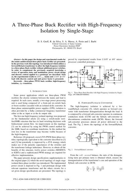
The paper presents design specifications supplementaries to<br />
the original paper [1] which the novel topology of single stage<br />
isolated three-phase rectifier was introduced. The implemented<br />
power circuit is depicted in Fig. 1 and prototype design <strong>with</strong><br />
relevant equations transformer and the others circuits for a<br />
set given design specifications are presented. The topology is<br />
Fig. 1. <strong>Three</strong>-<strong>Phase</strong> <strong>Buck</strong> <strong>Rectifier</strong> <strong>with</strong> <strong>High</strong>-<strong>Frequency</strong> <strong>Isolation</strong> by Single-<br />
Stage. (PCT/BR2007/000084)<br />
II. FORWARD/FLYBACK CONVERTER<br />
The high-frequency isolation is achieved by a forward/flyback<br />
converter [5], which operates as forward converter<br />
<strong>with</strong> transformer demagnetization through the load. It<br />
is composed by a forward sub-converter operates in continuous<br />
conduction mode (CCM) and the flyback sub-converter in<br />
discontinuous conduction mode (DCM). Hence, the forward<br />
sub-converter processes almost all power delivered to the<br />
load. The Fig. 2 shows the topology of the forward/flyback<br />
converter.<br />
Fig. 2.<br />
E<br />
Sw<br />
+ _ Lm<br />
Np<br />
Forward/flyback converter.<br />
Ns<br />
Nd<br />
From the volt · second balance, the ratio of the demagnetizing<br />
turns per primary turns is obtained which, ensures the<br />
demagnetization of the transformer’s core and operation of the<br />
flyback sub-converter in DCM.<br />
Ds<br />
Dd<br />
Lo<br />
D RL<br />
N d<br />
≤ V o (1 − D) ·<br />
N p E D<br />
Co<br />
Ro<br />
(1)<br />
978-1-4244-1668-4/08/$25.00 ©2008 IEEE<br />
1129<br />
Authorized licensed use limited to: UNIVERSIDADE FEDERAL DE SANTA CATARINA. Downloaded on November 13, 2009 at 06:41 from IEEE Xplore. Restrictions apply.
III. OPERATION STATES<br />
The operation states to a sextant of mains angular period<br />
is commented in this section. At each sextant 4 states can be<br />
always identified, in following figures the considered sextant<br />
is between 0 o and 60 o <strong>with</strong> states 1, 2 and 0 involved.<br />
Fig.3 the switches S2 and S3 are enable and the energy<br />
is transfer through transformer to load by Ds diode. Fig.4 the<br />
switches S1 and S2 are enable and the energy transfer through<br />
transformer to load is continued by Ds diode.<br />
iv ca<br />
D1n’<br />
D1p’<br />
Fig. 3.<br />
Ip<br />
D1p<br />
D2p<br />
D3p<br />
Ds Lo<br />
D2n’<br />
D3n’<br />
Ns<br />
Drl<br />
S1<br />
S2<br />
S3 Np<br />
Iv cb Iv cc<br />
D1n<br />
D2p’<br />
First state.<br />
D2n<br />
Estado1<br />
Ip<br />
D1p<br />
D2p<br />
D3p<br />
Ds Lo<br />
D1n’<br />
D2n’<br />
D3n’<br />
Ns<br />
Drl<br />
S1<br />
S2<br />
S3 Np<br />
iv ca Iv cb<br />
Iv cc<br />
D1p’<br />
D2p’<br />
D3p’<br />
D3p’<br />
D3n<br />
Nd<br />
Nd<br />
Dd<br />
Co<br />
Co<br />
Ro<br />
Ro<br />
IV. PROTOTYPE DESIGN AND IMPLEMENTATION<br />
In order to demonstrate the feasibility for the topology an<br />
experimental prototype was designed according the project set:<br />
V line−line = 220V ; f s =30kHz; P o =2.5kW; V o =48V .<br />
A. Input Filter Design<br />
An appropriate design of the AC input filter was carried<br />
out to provide a high power-factor, and T.H.D of line current<br />
intending to complain <strong>with</strong> IEC 61000-3-2 A Class, it was employed<br />
a classical low-pass LC filter which has a capacitance<br />
value defined according to the equation below:<br />
C f ≤<br />
2 · P o<br />
3 · η · ω · Vcf<br />
2 · tan(cos −1 (φ)) = 25μF (2)<br />
The presented parameters at equation 2 are defined as follow:<br />
V cf = 180V peak input filter capacitor voltage; η = 0.8<br />
estimated overall efficiency; φ =0, 99 estimated displacement<br />
factor and ω =2· π · f line frequency. It was decided by<br />
an Epcos polypropylene power capacitor C f = 22μF and<br />
defined a cut frequency for the input filter at 280Hz results<br />
an input filter inductance L s = 190μH.<br />
Fig. 4.<br />
D1n<br />
Second state.<br />
D2n<br />
Estado2<br />
D3n<br />
When the switches on the rectifier bridge are disenable the<br />
magnetization is extinct by Dd diode through the load in Fig.5.<br />
In order to assure a complete demagnetization a dead time is<br />
provided by a free-wheel current circulation in the end of 0<br />
state, see Fig.6.<br />
Dd<br />
B. Transformer Design<br />
The design procedure is based on usual equations to design<br />
E core high-frequency transformers where it was defined by<br />
following constrains parameters: ΔB =0.18T esla variation<br />
flux density ; J = 450 A<br />
cm<br />
current density; k 2<br />
p =0.7 winding<br />
fill factor; k w =0.4 spool factor.<br />
AeAw =<br />
2 · P o · 10 4<br />
k p · k w · J · f s · ΔB · η =98cm4 (3)<br />
D1p<br />
D2p<br />
D3p<br />
Ds Lo<br />
D1n’<br />
D2n’<br />
D3n’<br />
Ns<br />
Drl<br />
S1<br />
S2<br />
S3<br />
Np<br />
iv ca Iv cb<br />
Iv cc<br />
D1p’<br />
D2p’<br />
D3p’<br />
Nd<br />
D1n<br />
D2n<br />
D3n<br />
Dd<br />
Estado0<br />
Fig. 5. Demagnetization state.<br />
Co<br />
Ro<br />
It was selected a core E75/IP12 which were associated three<br />
cores in order to exceed the calculated AeAw at equation 3<br />
where it was obtained a AeAw = 125cm 4 and a total crosssectional<br />
area Ae =19.35cm 2 .<br />
The number of turns to each transformer winding are<br />
defined by the following equations where V retmax = 311V<br />
maximum rectified voltage; V retmin = 290V minimum rectified<br />
voltage; D M =0.5 maximum duty cycle and D =0.3<br />
average duty cycle:<br />
D1p<br />
D2p<br />
D3p<br />
Ds Lo<br />
D1n’<br />
D2n’<br />
D3n’<br />
Ns<br />
Drl<br />
S1<br />
S2<br />
S3<br />
Np<br />
iv ca Iv cb<br />
Iv cc<br />
D1p’<br />
D2p’<br />
D3p’<br />
Nd<br />
D1n<br />
D2n<br />
D3n<br />
Dd<br />
Co<br />
Ro<br />
N p = V ret min · 10 4<br />
2 · Ae · ΔB · f s<br />
=14turns (4)<br />
N s =1.1 · Np · (V o +1.5 · D)<br />
D · V retmin<br />
=9turns (5)<br />
Fig. 6.<br />
Free-wheel state.<br />
Estado0<br />
N d = N p ·<br />
V o<br />
V retmax<br />
· (1 − D M )<br />
D M<br />
=2turns (6)<br />
1130<br />
Authorized licensed use limited to: UNIVERSIDADE FEDERAL DE SANTA CATARINA. Downloaded on November 13, 2009 at 06:41 from IEEE Xplore. Restrictions apply.
C. <strong>Rectifier</strong> Bridge Design<br />
The <strong>Buck</strong> rectifier operates at forced-commutation, therefore<br />
to power switches and diodes bridge more careful consideration<br />
has to be given to choice these devices.<br />
The RCD snubbers were associated to the power switches<br />
to control the voltage rise rate reducing the stress and power<br />
dissipation in switch at turn-off, the Fig.1 presents the snubbers<br />
and switches association. For this design, 600V 55A<br />
IGBT’s were selected.<br />
For this design the peak switch voltage unless turn-off is:<br />
V swpk =<br />
{<br />
Np<br />
N d<br />
· V o for<br />
√<br />
2 · Vline for<br />
N p<br />
N d<br />
N p<br />
N d<br />
· V o > √ 2 · V line<br />
· V o ≤ √ 2 · V line<br />
Iv ia (t)<br />
Iv (t)<br />
Ib<br />
Iv (t)<br />
Ic<br />
Ki<br />
Ii Ia<br />
(t)<br />
Ii Ib<br />
(t)<br />
Ii Ic<br />
(t)<br />
Ii a (t) Ii b (t) Ii c (t)<br />
Anti-aliasing<br />
Filter<br />
Non-inverter<br />
Adder<br />
2.5V<br />
Ls<br />
Ls<br />
Ls<br />
Ii ia(t)<br />
Ii (t)<br />
Ib<br />
Ii (t)<br />
Ic<br />
Cf<br />
10 bits AD<br />
Converter<br />
Cf<br />
Cf<br />
M ia(t)<br />
M<br />
Ib<br />
(t) M (t)<br />
Ic<br />
Clarke-Park<br />
Transform<br />
Unidirectional<br />
<strong>Three</strong>-<strong>Phase</strong> PWM<br />
<strong>Buck</strong> <strong>Rectifier</strong><br />
Drive<br />
Ii (k)<br />
q<br />
Ii (k)<br />
d<br />
XOR<br />
I Qref<br />
Ii Dref (k)<br />
Np<br />
2 level<br />
Inverse Clarke-<br />
Park Transform<br />
M (k)<br />
d<br />
Ns<br />
Nd<br />
PWM<br />
Ds<br />
M (k)<br />
q<br />
Current<br />
Controlers<br />
Voltage<br />
Controler<br />
Drl<br />
Lo<br />
V Oref<br />
Co<br />
10 bits AD<br />
Converter<br />
Ro<br />
Kv<br />
Anti-aliasing<br />
Filter<br />
D. Output Design<br />
The output design regards the secondary diodes, D s , D RL ,<br />
D d , and output filter LC. The diodes D s and D RL were<br />
preserved by voltage clamping illustrated in Fig.1. For this<br />
design, 400V 115A Ultrafast rectifier diodes were selected to<br />
D s and D RL and a RCD clamp <strong>with</strong> resistance of 5.8kΩ<br />
and a capacitance of 150nF was applied. The output filter is<br />
composed by 100V electrolytic capacitors in parallel <strong>with</strong> total<br />
capacitance of 4400μF and the inductors were designed for<br />
a total inductance of 600μH composed by two toroidal core<br />
inductors of 300μH.<br />
Fig. 7.<br />
Discrete control loop block diagram.<br />
E. Controller Board Design<br />
The conditioning signal circuits, 2.5V offset circuits<br />
and adder circuits were designed to operational amplifier<br />
OPA2222. The sampled currents and voltages are processed<br />
for dsPIC30F4011, <strong>with</strong> 16 bit digital signal microcontroller,<br />
10 bit AD converters and up to 30MIPS instruction processing.<br />
The sampling frequency is 15kHz <strong>with</strong> a PWM frequency<br />
into dsPIC of 15kHz. At first stage of signal conditioning<br />
it was designed an anti-aliasing filter <strong>with</strong> characteristic frequency<br />
of 2.5kHz. In order to eliminate the negative values of<br />
sampled line current it was designed a non-inverter adder for<br />
2.5V offset.<br />
The three-level modulation was implemented through a<br />
XOR TTL integrated circuit in order to improve the processing<br />
time on dsPIC and this PWM is used as input signal to<br />
commercial IGBT’s drives.<br />
The block diagram depicted in Fig. 7 comprises the isolated<br />
buck rectifier and the main blocks to the discrete control<br />
implementation based on dsPIC microcontroller technology.<br />
The picture Fig.8 illustrates the prototype, where in the left<br />
are the AC input filter, inductors and film power capacitors,<br />
in the middle is the <strong>Buck</strong> rectifier bridge, in the right the<br />
transformer and the output filter. Attached to front of prototype<br />
is the conditioning, processing and controller board.<br />
V. DESIGN OF DISCRETE CONTROL<br />
The AC and DC models were obtained based on phase<br />
variables in the dqo coordinates system according the previous<br />
Fig. 8.<br />
Implemented experimental prototype.<br />
article [1]. The both models present a second-order characteristics<br />
for the AC input currents, G i (z), and the DC load voltage,<br />
G v (z), as represented by the discrete transfer functions below:<br />
G i (z) =7, 38 ·<br />
G i (z) ⇐ ZOH(s) · G i (s) (7)<br />
(z +2, 39) · (z +0, 156)<br />
(z − 0, 12) · (z 2 − 1, 01z +0, 96)<br />
(8)<br />
G v (z) ⇐ ZOH(s) · G v (s) (9)<br />
(z 2 − 1, 01z +0, 84)<br />
G v (z) =0, 03 ·<br />
(z − 0, 12) · (z 2 (10)<br />
− 1, 97z +0, 98)<br />
The closed-loop uses PI discrete controller, which were<br />
designed to control the rectifier by the load voltage and the<br />
input currents and them implementation at assembly code<br />
obtained through deference equations. Such as,the designed<br />
discrete transfer function for the current controller, C i (z), and<br />
voltage controller, C v (z) are specified by:<br />
C i (z) =0, 000436 ·<br />
z − 0, 178<br />
z − 1<br />
(11)<br />
1131<br />
Authorized licensed use limited to: UNIVERSIDADE FEDERAL DE SANTA CATARINA. Downloaded on November 13, 2009 at 06:41 from IEEE Xplore. Restrictions apply.
C v (z) =0, 0276 ·<br />
z − 0, 983<br />
z − 1<br />
(12)<br />
VI. EXPERIMENTAL RESULTS<br />
Operation and performance of designed prototype are illustrated<br />
by the following experimental results obtained at load<br />
resistance of 0.89Ω exceeding the designed power of 2.5kW.<br />
The Fig.9 shows an input reference phase voltage and input<br />
current, which is perceived the quality for the input current<br />
in phase <strong>with</strong> the voltage. Fig.10 shows the three-phase input<br />
currents where phase a presents low distortion, phase b and c<br />
are almost sinusoidal. The input capacitor voltage and current<br />
are illustrated at Fig.11 where the current carries the high<br />
frequency harmonics generated by PWM <strong>Buck</strong> rectifier bridge<br />
<strong>with</strong> relevant peak current that shall be consider when chosen<br />
the capacitor.<br />
Fig. 11.<br />
Input capacitor voltage an current.<br />
and the measured efficiency at four different values of load<br />
resistance at dotted line. The overall efficiency at full load is<br />
around 80%.<br />
Fig. 9.<br />
<strong>Phase</strong> voltage and current.<br />
Fig. 12.<br />
Switch voltage and current.<br />
Fig. 13.<br />
Secondary voltage and current.<br />
Fig. 10.<br />
Input currents.<br />
Fig.12 shows the voltage and current in a power switch,<br />
upper is a view at low frequency and below is the expanded<br />
view <strong>with</strong> voltage and current follow the safety and expected<br />
behavior performed by the snubber assistance. Fig.13 shows<br />
the secondary winding voltage and current as well as the<br />
demagnetization current. Fig.14 shows the load voltage and<br />
current at steady state and the Fig.15 shows the soft-start<br />
achieved <strong>with</strong>out auxiliary circuits for the prototype. The<br />
power quality is proved in the Fig.16 <strong>with</strong> a total harmonic<br />
distortion of 6.4% and power factor of 0.998 both to phase a.<br />
Fig.17 shows the estimated prototype efficiency at bold line<br />
VII. CONCLUSION<br />
A prototype design, operation and performance of a threephase<br />
<strong>Buck</strong> rectifier <strong>with</strong> high-frequency isolation by singlestage<br />
was presented and demonstrates the concepts introduced<br />
at original work [1].<br />
The topology operates at forced-commutation and achieved<br />
a reasonable 80% overall efficiency at full load although considering<br />
the dissipated power at snubbers and clamp circuits.<br />
Otherwise, comparing <strong>with</strong>in others isolated topologies this<br />
requires three power switches and twelve diodes into rectifier<br />
instead of ten or twelve power switches and fast diodes. Such<br />
1132<br />
Authorized licensed use limited to: UNIVERSIDADE FEDERAL DE SANTA CATARINA. Downloaded on November 13, 2009 at 06:41 from IEEE Xplore. Restrictions apply.
attention should be taken regarding the comprise of voltage<br />
and current ratings as well as commutation frequency to a<br />
safety operation, i.e. these will be determinant to the rectifiers<br />
design and pretense application.<br />
Therefore, this isolated single stage rectifier is a alternative<br />
solution for medium-power and high input voltage<br />
applications, e.g. telecommunication power supplies or UPS<br />
systems which would uses boost rectifiers <strong>with</strong> high-frequency<br />
isolation by additional stage.<br />
Fig. 14.<br />
Fig. 15.<br />
Load voltage and current.<br />
Load voltage and current at start.<br />
REFERENCES<br />
[1] Greff, D., <strong>Barbi</strong> I.; A Single-Stage <strong>High</strong>-<strong>Frequency</strong> Isolated <strong>Three</strong>-<strong>Phase</strong><br />
AC/DC Converter., IEEE IECON’06, The 32nd Annual Conference of<br />
the IEEE Industrial Electronics Society, November 2006.<br />
[2] Manias, S.; Ziogas, P. D.,A Novel Sinewave in AC to DC <strong>with</strong> <strong>High</strong>-<br />
<strong>Frequency</strong> Transformer <strong>Isolation</strong>, IEEE Transactions on Industry Electronis,<br />
Vol.IE-32, No.4, pp. 430-438, 1985.<br />
[3] Inagaki, K.; Furuhashi, T.; Ishiguro, A.; Ishida, M.; Okuma, S.,A new<br />
PWM control method for ac to dc converters <strong>with</strong> high-frequency<br />
transformer isolation, IEEE Industry Application Society Conference<br />
Proc. 1989, pp. 783-789.<br />
[4] Vlatkovic, V.; Borojevic, B.; Lee, F. C.,A Zero-Voltage Switched, <strong>Three</strong>-<br />
<strong>Phase</strong> Isolated PWM <strong>Buck</strong> <strong>Rectifier</strong>, IEEE Transactions on Power<br />
Electronics, Vol.10, No.2, March 1995.<br />
[5] Park, J.N.; Zaloum, T.R.,A Dual Mode Forward/Flyback Converter,<br />
IEEE Power Electronics Specialists Conference, PESC’82 Record, 1982,<br />
pp. 3-13.<br />
[6] Malesani, L.; Tenti, P.,<strong>Three</strong>-<strong>Phase</strong> AC/DC PWM Converter <strong>with</strong> Sinusoidal<br />
AC Currents and Minimum Filter Requirements, IEEE Transactions<br />
on Industry Applications, Vol. IA-23, No.1, January/February<br />
1987.<br />
Fig. 16.<br />
Power quality analysis.<br />
83<br />
82<br />
81<br />
80<br />
Po %<br />
79<br />
78<br />
77<br />
76<br />
30 40 50 60 70 80 90 100 110 120<br />
Efficiency %<br />
Fig. 17.<br />
Prototype efficiency as function of %load power.<br />
as the efficiency curve demonstrates values at light load near<br />
to full load presents an almost linear operation.<br />
Concisely being a buck or a forward converter an special<br />
1133<br />
Authorized licensed use limited to: UNIVERSIDADE FEDERAL DE SANTA CATARINA. Downloaded on November 13, 2009 at 06:41 from IEEE Xplore. Restrictions apply.