

The Clansman UK/PRC-351 and its Variants - VMARSmanuals
The Clansman UK/PRC-351 and its Variants - VMARSmanuals
The Clansman UK/PRC-351 and its Variants - VMARSmanuals

Create successful ePaper yourself
Turn your PDF publications into a flip-book with our unique Google optimized e-Paper software.
<strong>The</strong> VMARS Newsletter Issue 42<br />
<strong>The</strong>re are 4 test points on the RT-<strong>351</strong> chassis:<br />
TP1 Varicap tuning voltage<br />
TP2 Frequency of VCO in service<br />
TP3 Output from synthesiser phase detector<br />
TP4 6V supply<br />
Frequency Synthesiser<br />
transmit there is no sidetone. <strong>The</strong>se features are designed<br />
to alert the operator to a set malfunction.<br />
Consider what happens if (say) the LC components of the<br />
receiver high b<strong>and</strong> local oscillator circuit change value with age<br />
or are mistuned in error. Suppose this results in phase lock<br />
being achieved at 76 MHz on the frequency setting switches,<br />
with a VCO frequency of 76 + 11.525MHz (i.e. signal plus IF)<br />
but with only 60 volts on TP1 rather than the design value of 83<br />
volts. <strong>The</strong> confidence check will be positive <strong>and</strong> all will appear<br />
to be in order. However, the receiver RF circu<strong>its</strong> will not be<br />
aligned to the oscillator since they require 83 volts to tune to 76<br />
MHz. <strong>The</strong> set will not be operating correctly. This demonstrates<br />
that the <strong>PRC</strong>-<strong>351</strong> is complex <strong>and</strong> all might not be as simple as<br />
it seems. Trial tuning <strong>and</strong> twiddling is not recommended.<br />
Internal Power Supplies<br />
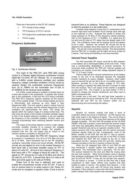
Fig. 4 Synthesiser Module<br />
<strong>The</strong> heart of the <strong>PRC</strong>-<strong>351</strong> (<strong>and</strong> <strong>PRC</strong>-350) tuning<br />
control is a Plessey digital frequency synthesiser module<br />
(5820-99-110-3478, RT-<strong>351</strong> Module 10). In combination<br />
with a 6.4MHz crystal reference oscillator <strong>and</strong> variable<br />
frequency voltage controlled oscillators (VCOs) tuned by<br />
varactor diodes, the synthesiser produces frequencies<br />
from 30 to 76MHz for the transmitter <strong>and</strong> 41.525 to<br />
87.525MHz for the receiver local oscillator.<br />
A 6.4 MHz crystal reference oscillator is divided down by<br />
a fixed ratio divider in the synthesiser. A variable ratio divider,<br />
also in the synthesiser, is fed from the VCO being controlled.<br />
<strong>The</strong> <strong>PRC</strong>-<strong>351</strong>'s frequency selector switches set the division<br />
ratio of the variable divider. <strong>The</strong> two divided signals are fed to<br />
a discriminator that produces an error signal if their<br />
frequencies differ. <strong>The</strong> error signal is used to coarse tune the<br />
VCO via varactor diodes until the divided frequencies of both<br />
oscillators are approximately the same. This brings the<br />
signals within the capture range of a phase locked loop. <strong>The</strong><br />
loop locks the phase of the divided controlled oscillator signal<br />
to that of the divided reference oscillator to set <strong>and</strong> stabilise<br />
the frequency of the controlled oscillator. Division ratios are<br />
changed automatically when switching between receive <strong>and</strong><br />
transmit.<br />
<strong>The</strong> output of the phase detector is fed to a high voltage,<br />
non-linear amplifier (module 8) to produce the voltages<br />
necessary to tune the varactor diodes. <strong>The</strong> amplifier is<br />
powered from the 100 volt supply <strong>and</strong> <strong>its</strong> output to the<br />
varactor diodes is available on test point TP1.<br />
As previously stated the <strong>PRC</strong>-<strong>351</strong> frequency range<br />
is covered in 2 waveb<strong>and</strong>s, from 30 to 47.975 MHz <strong>and</strong> from<br />
48 to 76 MHz. Each waveb<strong>and</strong> has <strong>its</strong> own RF amplifiers,<br />
oscillators, transmitter drivers <strong>and</strong> tuned circu<strong>its</strong>. All the RF<br />
circu<strong>its</strong> are pre-aligned to tune to the lowest frequency in<br />
their b<strong>and</strong> with a non-linear amplifier output on TP1 of<br />
about 4.5 volts DC. All tune to the maximum frequency in<br />
their b<strong>and</strong> with a TP1 voltage of about 83 volts DC. <strong>The</strong><br />
signal on TP1 should be 4.5 volts at 30 MHz <strong>and</strong> climb to<br />
83 volts DC at 47.975. It should then fall to 4.5 volts at 48<br />
MHz <strong>and</strong> climb again to 83 volts at 76 MHz.<br />
Phase lock of the loop is detected <strong>and</strong> used to<br />
enable the conventional circu<strong>its</strong> of the RT-<strong>351</strong>. If lock is<br />
lost on receive there is no audio output in the `Noise On'<br />
mode <strong>and</strong> no reception in squelch mode. If lock is lost on<br />
<strong>The</strong> A42 transmitter RF output could fall by 66% between<br />
a new battery <strong>and</strong> a discharged battery at the end of life. <strong>The</strong>re<br />
was a corresponding degradation in receiver sensitivity. To<br />
overcome these problems the <strong>PRC</strong>-<strong>351</strong> internal supplies are<br />
provided by an inverter circuit with voltage regulated outputs of<br />
100, 17, 9, 6 <strong>and</strong> 3 Volts.<br />
<strong>The</strong>re is little fall off in receiver performance as the battery<br />
comes to the end of <strong>its</strong> discharge because the regulated<br />
inverter maintains <strong>its</strong> output voltages. However, when called<br />
upon to transmit the set can fail to do so. An audible warning is,<br />
therefore, provided for a low battery voltage of 19.5 volts.<br />
When working in squelch this takes the form of pulses of noise<br />
from the receiver. <strong>The</strong> 6 volt output of the inverter is available<br />
on test point TP4. <strong>The</strong> inverter is not fault limited. If TP4 is<br />
shorted to chassis the inverter transformer <strong>and</strong> other hard to<br />
obtain components fail.<br />
<strong>The</strong> inverter has a soft start. <strong>The</strong> soft start timer capacitor is<br />
discharged when the set is switched to OFF. <strong>The</strong> set should be<br />
switched ON <strong>and</strong> OFF by the function switch not by<br />
disconnecting <strong>and</strong> reconnecting the battery.<br />
Squelch<br />
Squelch (or receiver muting) had been a bone of<br />
contention before the arrival of <strong>Clansman</strong>. An FM receiver has<br />
high noise output in the absence of signal. This can be tiring to<br />
listen to for long periods. <strong>The</strong> noise level reduces as the signal<br />
strength increases. <strong>The</strong> first VHF FM portable set the US SCR<br />
300/BC 1000 had a squelch control that kept the receiver muted<br />
until noise was adequately reduced by an incoming signal. <strong>The</strong><br />
squelch threshold was set by an operator variable control. This<br />
raised concerns that if the operator set the control incorrectly<br />
important signals might be lost. Consequently, most of the<br />
British variants of the SCR 300, the WS 31, had no squelch.<br />
Variable squelch was retained by the US on the <strong>PRC</strong>-10 series<br />
that replaced the SCR 300 but omitted by the <strong>UK</strong> on their<br />
equivalents, the No.1 versions of the A41 <strong>and</strong> A42. Muting was<br />
however provided on the No.2 versions of those <strong>UK</strong> sets.<br />
When the US designed their VRC-12 <strong>and</strong> <strong>PRC</strong>-25 sets<br />
they introduced a squelch system that needed no operator<br />
adjustment. <strong>The</strong> transmitters had a sub-audio, 150 Hz tone.<br />
<strong>The</strong> receiver listened for this tone <strong>and</strong> lifted the muting when<br />
the tone was received. When the Europeans came to develop<br />
their analogue synthesised VHF FM radios such as the SEM 25<br />
<strong>and</strong> 35 <strong>and</strong> the TR-PP 13 they did not provide tone squelch.<br />
<strong>The</strong> full reason is unclear - it could be that they had a large<br />
compliment of older radios without tone squelch that they<br />
wished to retain in service. <strong>The</strong> position then became – if the<br />
<strong>UK</strong> wanted to cross work with US forces tone squelch was<br />
necessary. If they wished to cross work with the Europeans <strong>and</strong><br />
earlier Larkspur sets noise squelch was necessary.<br />
5 August 2005


