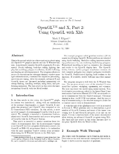
OpenGLTM and X, Part 2: Using OpenGL with Xlib
OpenGLTM and X, Part 2: Using OpenGL with Xlib
OpenGLTM and X, Part 2: Using OpenGL with Xlib

Create successful ePaper yourself
Turn your PDF publications into a flip-book with our unique Google optimized e-Paper software.
To be published in the<br />
January/February issue of The X Journal.<br />
<strong>OpenGL</strong> TM <strong>and</strong> X, <strong>Part</strong> 2:<br />
<strong>Using</strong> <strong>OpenGL</strong> <strong>with</strong> <strong>Xlib</strong><br />
Mark J. Kilgard 3<br />
Silicon Graphics Inc.<br />
Revision : 1:21<br />
January 18, 1994<br />
Abstract<br />
This is the second article in a three-part series about using<br />
the <strong>OpenGL</strong> TM graphics system <strong>and</strong> the X Window System.<br />
A moderately complex <strong>OpenGL</strong> program for X is presented.<br />
Depth buering, back-face culling, lighting, display<br />
list modeling, polygon tessellation, double buering,<br />
<strong>and</strong> shading are all demonstrated. The program adheres to<br />
proper X conventions for colormap sharing, window manager<br />
communication, comm<strong>and</strong> line argument processing,<br />
<strong>and</strong> event processing. After the example, advanced X <strong>and</strong><br />
<strong>OpenGL</strong> issues are discussed including minimizing colormap<br />
ashing, h<strong>and</strong>ling overlays, using fonts, <strong>and</strong> performing<br />
animation. The last article in this series discusses<br />
integrating <strong>OpenGL</strong> <strong>with</strong> the Motif toolkit.<br />
1 Introduction<br />
In the rst article in this series, the <strong>OpenGL</strong> TM graphics<br />
system was introduced. Along <strong>with</strong> an explanation<br />
of the system's functionality, a simple <strong>OpenGL</strong> X program<br />
was presented <strong>and</strong> <strong>OpenGL</strong> was compared to the<br />
X Consortium's PEX extension. In this article, a more<br />
involved example of programming <strong>OpenGL</strong> <strong>with</strong> X is presented.<br />
The example is intended to demonstrate both sophisticated<br />
<strong>OpenGL</strong> functionality <strong>and</strong> proper integration<br />
of <strong>OpenGL</strong> <strong>with</strong> the X Window System.<br />
This article is intended to answer questions from two<br />
classes of programmers: rst, the X programmer wanting<br />
to see <strong>OpenGL</strong> used in a program of substance; second, the<br />
<strong>OpenGL</strong> or IRIS GL programmer likely to be unfamiliar<br />
<strong>with</strong> the more mundane window system setup necessary<br />
when using the X Window System at the <strong>Xlib</strong> layer.<br />
3 Mark graduated <strong>with</strong> B.A. in Computer Science from Rice University<br />
<strong>and</strong> is a Member of the Technical Sta at Silicon Graphics.<br />
He can be reached by electronic mail addressed to mjk@sgi.com<br />
The example program called glxdino renders a 3D dinosaur<br />
model using <strong>OpenGL</strong>. Hidden surfaces are removed<br />
using depth buering. Back-face culling improves rendering<br />
performance by not rendering back-facing polygons.<br />
Hierarchical modeling is used to construct the dinosaur<br />
<strong>and</strong> render it via <strong>OpenGL</strong> display lists. The <strong>OpenGL</strong><br />
tility Library (GL ) polygon tessellation routines divide<br />
complex polygons into simpler polygons renderable<br />
by <strong>OpenGL</strong>. Sophisticated lighting lends realism to the<br />
dinosaur. If available, double buering smoothes animation.<br />
The program integrates well <strong>with</strong> the X Window System.<br />
The program accepts some of the st<strong>and</strong>ard X comm<strong>and</strong><br />
line options: -display, -geometry, <strong>and</strong> -iconic.<br />
The user can rotate the model using mouse motion. Toplevel<br />
window properties specied by the Inter-Client Communication<br />
Convention Manual (ICCCM) are properly set<br />
up to communicate <strong>with</strong> the window manager. Colormap<br />
sharing is done via ICCCM conventions. And the proper<br />
way of communicating to the window manager a desire for<br />
a constant aspect ratio is demonstrated.<br />
A walk through of the glxdino source code is presented<br />
in Section 2. While glxdino tries to demonstrate a good<br />
number of <strong>OpenGL</strong> features <strong>and</strong> many of the issues concerning<br />
how X <strong>and</strong> <strong>OpenGL</strong> integrate, it is only an example.<br />
Section 3 explores more of the issues encountered<br />
when writing an advanced <strong>OpenGL</strong> program using <strong>Xlib</strong>.<br />
The third <strong>and</strong> last article in this series discusses how to<br />
integrate <strong>OpenGL</strong> <strong>with</strong> the Motif toolkit.<br />
a l al rou<br />
The source code for glxdino can be found in Appendix A.<br />
I will refer to the code repeatedly throughout this section.<br />
Figure 1 shows a screen snapshot of glxdino.<br />
1
.<br />
Figure 1: Screen snapshot of glxdino.<br />
The program's initialization proceeds through the following<br />
steps:<br />
1. Process the st<strong>and</strong>ard X comm<strong>and</strong> line options.<br />
2. Open the connection to the X server.<br />
3. Determine if <strong>OpenGL</strong>'s GLX extension is supported.<br />
. Find the appropriate X visual <strong>and</strong> colormap.<br />
5. Create an <strong>OpenGL</strong> rendering context.<br />
6. Create an X window <strong>with</strong> the selected visual <strong>and</strong><br />
properly specify the right ICCCM properties for the<br />
window manager to use.<br />
. Bind the rendering context to the window.<br />
8. Make the display list hierarchy for the dinosaur<br />
model.<br />
9. Congure <strong>OpenGL</strong> rendering state.<br />
10. Map the window.<br />
11. Begin dispatching X events.<br />
Comments in the code correspond to these enumerated<br />
steps.<br />
In the program's main routine, the rst task is to process<br />
the supported comm<strong>and</strong> line arguments. sers of the X<br />
Window System should be familiar <strong>with</strong> -display which<br />
species the X server to use, -geometry which species<br />
the initial size <strong>and</strong> location of the program's main window,<br />
<strong>and</strong> -iconic which requests the window be initially<br />
iconied. Programmers used to the IRIS GL (the predecessor<br />
to <strong>OpenGL</strong>) may not be familiar <strong>with</strong> these options.<br />
While nothing requires an X program to accept st<strong>and</strong>ard<br />
X options, most do as a matter of consistency <strong>and</strong> convenience.<br />
Most X toolkits automatically underst<strong>and</strong> the<br />
st<strong>and</strong>ard set of X options<br />
The - eepaspect option is not a st<strong>and</strong>ard X comm<strong>and</strong><br />
line option. When specied, it requests that the window<br />
manager ensure that the ratio between the initial width<br />
<strong>and</strong> height of the window be maintained. Often for 3D<br />
programs, the programmer would like a constant aspect<br />
ratio for their rendering window. In IRIS GL, a call named<br />
eepaspect is available. Maintaining the aspect ratio of<br />
a window is something for the window system to do so<br />
there is no call analogous to IRIS GL's eepaspect in<br />
<strong>OpenGL</strong>. Remember that the core <strong>OpenGL</strong> Application<br />
Programmer Interface (API) attempts to be window system<br />
independent. IRIS GL programmers used to the IRIS<br />
GL interface will need to become aware of X functionality<br />
to do things that used to be done <strong>with</strong> IRIS GL calls.<br />
ormally glxdino tries to use a double buered window<br />
but will use a single buered window if a double<br />
buered visual is not available. When the -single option<br />
is present, the program will look only for a single<br />
buered visual. On many machines <strong>with</strong> hardware double<br />
buering support, color resolution can be traded for double<br />
buering to achieve smooth animation. For example,<br />
a machine <strong>with</strong> 2 bits of color resolution could support<br />
12 bits of color resolution for double buered mode. Half<br />
the image bit-planes would be for the front buer <strong>and</strong> half<br />
for the back buer.<br />
ext, a connection to the X server is established using<br />
pen isplay. Since glxdino requires <strong>OpenGL</strong>'s GLX<br />
extension, the program checks that the extension exists<br />
using gl uery xtension. The routine indicates if the<br />
GLX extension is supported or not. As is convention for<br />
X routines that query extensions, the routine can also return<br />
the ase error co e <strong>and</strong> ase event co e for the GLX<br />
extension. The current version of GLX supports no extension<br />
events (but does dene eight protocol errors). Most<br />
<strong>OpenGL</strong> programs will need neither of these numbers. ou<br />
can pass in as glxdino does to indicate you do not<br />
need the event or error base.<br />
<strong>OpenGL</strong> is designed for future extensibility. The<br />
gl uery ersion routine returns the ma or <strong>and</strong> minor<br />
version of the <strong>OpenGL</strong> implementation. Currently, the<br />
ma or version is 1 <strong>and</strong> the minor version is 0. glxdino<br />
does not use gl uery ersion but it may be useful for<br />
programs in the future.<br />
. .<br />
The GLX extension overloads X visuals to denote supported<br />
frame buer congurations. Before you create an<br />
<strong>OpenGL</strong> window, you should select a visual which sup-<br />
2
ports the frame buer features you intend to use. GLX<br />
guarantees at least two visual will be supported. An<br />
RGBA mode visual <strong>with</strong> a depth buer, stencil buer, <strong>and</strong><br />
accumulation buer must be supported. Second, a color<br />
index mode visual <strong>with</strong> a depth buer <strong>and</strong> stencil buer<br />
must be available. More <strong>and</strong> less capable visuals are likely<br />
to also be supported depending on the implementation.<br />
To make it easy to select a visual, gl oose isual<br />
takes a list of the capabilities you are requesting <strong>and</strong> returns<br />
an isual n o for a visual meeting your requirements.<br />
is returned if a visual meeting your needs<br />
is not available. To ensure your application will run <strong>with</strong><br />
any <strong>OpenGL</strong> GLX server, your program should be written<br />
to support the base line required GLX visuals. Also you<br />
should only ask for the minimum set of frame buer capabilities<br />
you require. For example, if your program never<br />
uses a stencil buer, you will possibly waste resources if<br />
you request one anyway.<br />
Since glxdino rotates the dinosaur in response to user<br />
input, the program will run better if double buering is<br />
available. Double buering allows a scene to be rendered<br />
out of view <strong>and</strong> then displayed nearly instantly to eliminate<br />
the visual artifacts associated <strong>with</strong> watching a 3D<br />
scene render. Double buering helps create the illusion of<br />
smooth animation. Since double buering support is not<br />
required for <strong>OpenGL</strong> implementations, glxdino resorts<br />
to single buering if no double buer visuals are available.<br />
The program's con iguration integer array tells<br />
what capabilities gl oose isual should look for. o-<br />
tice how if a double buer visual is not found, another<br />
attempt is made which does not request double buering<br />
by starting after the<br />
token. And when<br />
the -single option is specied, the code only looks for a<br />
singled buered visual.<br />
glxdino does require a depth buer (of at least 16 bits<br />
of accuracy) <strong>and</strong> uses the RGBA color model. The RGBA<br />
base line visual must support at least a 16 bit depth buer<br />
so glxdino should always nd a usable visual.<br />
ou should not assume the visual you need is the<br />
default visual. sing a non-default visual means windows<br />
created using the visual will require a colormap<br />
matching the visual. Since the window we are interested<br />
in uses <strong>OpenGL</strong>'s RGBA color model, we want a<br />
colormap congured for using RGB. The ICCCM establishes<br />
a means for sharing RGB colormaps between clients.<br />
mu oo up t<strong>and</strong>ard olormap is used to set up a colormap<br />
for the specied visual. The routine reads the ICCCM<br />
property on the X server's root window.<br />
If the property does not exist or does not have an entry<br />
for the specied visual, a new RGB colormap is created<br />
for the visual <strong>and</strong> the property is updated (creating<br />
it if necessary). Once the colormap has been created,<br />
et olormaps nds the newly created colormap. The<br />
work for nding a colormap is done by the get olormap<br />
routine.<br />
If a st<strong>and</strong>ard colormap cannot be allocated, glxdino<br />
will create an unshared colormap. For some servers,<br />
it is possible (though unlikely) a irect olor visual<br />
might be returned (though the GLX specication requires<br />
a rue olor visual be returned in precedence to a<br />
irect olor visual if possible). To shorten the example<br />
code by only h<strong>and</strong>ling the most likely case, the code bails<br />
if a irect olor visual is encountered. A more portable<br />
(<strong>and</strong> longer) program would be capable of initializing an<br />
RGB irect olor colormap.<br />
. .<br />
Once a suitable visual <strong>and</strong> colormap are found, the program<br />
can create an <strong>OpenGL</strong> rendering context using<br />
gl reate ontext. (The same context can be used for<br />
dierent windows <strong>with</strong> the same visual.)<br />
The last parameter allows the program to request a direct<br />
rendering context if the program is connected to a<br />
local X server. An <strong>OpenGL</strong> implementation is not required<br />
to support direct rendering, but if it does, faster<br />
rendering is possible since <strong>OpenGL</strong> will render directly to<br />
the graphics hardware. Direct rendered <strong>OpenGL</strong> requests<br />
do not have to be sent to the X server. Even when on the<br />
local machine, you may not want direct rendering in some<br />
cases. For example, if you want to render to X pixmaps,<br />
you must render through the X server.<br />
GLX rendering contexts support sharing of display lists<br />
among one another. To this end, the third parameter to<br />
gl reate ontext is another already created GLX rendering<br />
context. can be specied to create an initial<br />
rendering context. If an already existent rendering context<br />
is specied, the display list indexes <strong>and</strong> denitions<br />
are shared by the two rendering contexts. The sharing is<br />
transitive so a share group can be formed between a whole<br />
set of rendering contexts.<br />
To share, all the rendering contexts must exist in the<br />
sa e address space. This means direct renderers cannot<br />
share display lists <strong>with</strong> renderers rendering through the<br />
X server. Likewise direct renderers in separate programs<br />
cannot share display lists. Sharing display lists between<br />
renderers can help to minimize the memory requirements<br />
of applications that need the same display lists.<br />
. .<br />
Because <strong>OpenGL</strong> uses visuals to distinguish various frame<br />
buer capabilities, programmers using <strong>OpenGL</strong> need to be<br />
aware of the required steps to create a window <strong>with</strong> a nondefault<br />
visual. As mentioned earlier a colormap created<br />
for the visual is necessary. But the most irksome thing<br />
to remember about creating a window <strong>with</strong> a non-default<br />
visual is that the border pixel value ust be specied if<br />
the window's visual is not the same as its parent's visual.<br />
Otherwise a ad atc is generated.<br />
3
Before actually creating the window, the argument<br />
to the -geometry option should be parsed using<br />
arse eometry to obtain the user's requested size <strong>and</strong><br />
location. The size will be needed when we create the window.<br />
Both the size <strong>and</strong> location are needed to set up the<br />
ICCCM size hints for the window manager. A xed aspect<br />
ratio is also requested by setting up the right size hints if<br />
the - eepaspect option is specied.<br />
Once the window is created, et t<strong>and</strong>ard roperties<br />
sets up the various st<strong>and</strong>ard ICCCM properties including<br />
size hints, icon name, <strong>and</strong> window name. Then the IC-<br />
CCM window manager hints are set up to indicate the<br />
window's initial state. The -iconic option sets the window<br />
manager hints to indicate the window should be initially<br />
iconied. lloc ints allocates a hints structure.<br />
Once lled in, et ints sets up the hint property for<br />
the window.<br />
The nal addition to the window is the<br />
property which indicates window manager protocols the<br />
client underst<strong>and</strong>s. The most commonly used protocol<br />
dened by ICCCM is<br />
. If this atom is<br />
listed in the<br />
property of a top-level window,<br />
then when the user selects the program be quit from the<br />
window manager, the window manager will politely send<br />
a<br />
message to the client instructing the<br />
client to delete the window. If the window is the application's<br />
main window, the client is expected to terminate. If<br />
this property is not set, the window manager will simply<br />
ask the X server to terminate the client's connection <strong>with</strong>out<br />
notice to the client. By default, this results in <strong>Xlib</strong><br />
printing an ugly message like:<br />
connection to : . ro en<br />
explicit ill or ser er s utdo n .<br />
Asking to participate in the<br />
protocol<br />
allows the client to safely h<strong>and</strong>le requests to quit from the<br />
window manager.<br />
The property has another advantage for <strong>OpenGL</strong> programs.<br />
Many <strong>OpenGL</strong> programs doing animation will use<br />
ending to check for pending X events <strong>and</strong> otherwise<br />
draw their animation. But if all a client's animation is direct<br />
<strong>OpenGL</strong> rendering <strong>and</strong> the client does not otherwise<br />
do any X requests, the client never sends requests to the<br />
X server. Due to a problem in ending's implementation<br />
on many nix operating systems, such an <strong>OpenGL</strong> program<br />
might not notice its X connection was terminated<br />
for sometime. sing the protocol eliminates<br />
this problem because the window manager noties<br />
perating systems using ioc calls on le descriptors<br />
using Berkeley non-blocking cannot dierentiate no data to read<br />
from a broken connection; both conditions cause the<br />
ioc<br />
to return ero. M T's st<strong>and</strong>ard implementation of i g uses<br />
Berkeley non-blocking <strong>and</strong> ioc s. ventually, lib<br />
will do an e plicit check on the socket to see if it closes but only<br />
after a couple hundred calls to i g.<br />
the client via a message (tripping ending) <strong>and</strong> the client<br />
is expected to drop the connection.<br />
sing the<br />
protocol is good practice<br />
even if you do not use ending <strong>and</strong> the <strong>Xlib</strong> message<br />
does not bother you.<br />
All these steps (besides creating a window <strong>with</strong> a nondefault<br />
visual) are st<strong>and</strong>ard for creating a top-level X window.<br />
A top-level window is a window created as a child<br />
of the root window (the window manager may choose to<br />
reparent the window when it is mapped to add a border).<br />
ote that the properties discussed are placed on the<br />
to -level window, not necessarily the same window that<br />
<strong>OpenGL</strong> renders into. While glxdino creates a single<br />
window, a more complicated program might nest windows<br />
used for <strong>OpenGL</strong> rendering inside the top-level window.<br />
The ICCCM window manager properties belong on toplevel<br />
windows only.<br />
An IRIS GL programmer not familiar <strong>with</strong> X will probably<br />
nd these details cumbersome. Most of the work will<br />
be done for you if you use a toolkit layered on top of <strong>Xlib</strong>.<br />
ow a window <strong>and</strong> an <strong>OpenGL</strong> rendering context exist.<br />
In <strong>OpenGL</strong> (unlike <strong>Xlib</strong>), you do not pass the rendering<br />
destination into every rendering call. Instead a<br />
given <strong>OpenGL</strong> rendering context is bound to a window<br />
using gl a e urrent. Once bound, all <strong>OpenGL</strong> rendering<br />
calls operate using the current <strong>OpenGL</strong> rendering<br />
context <strong>and</strong> the current bound window. A thread can only<br />
be bound to one window <strong>and</strong> one rendering context at a<br />
time. A context can only be bound to a single thread<br />
at a time. If you call gl a e urrent again, it unbinds<br />
from the old context <strong>and</strong> window <strong>and</strong> then binds to the<br />
newly specied context <strong>and</strong> window. ou can unbind a<br />
thread from a window <strong>and</strong> a context by passing for<br />
the context <strong>and</strong> one for the drawable.<br />
.<br />
The task of guring out how to describe the 3D ob ect<br />
you wish to render is called o el n . Much as a plastic<br />
airplane model is constructed out of little pieces, a computer<br />
generated 3D scene must also be built out of little<br />
pieces. In the case of 3D rendering, the pieces are generally<br />
polygons.<br />
The dinosaur model to be displayed is constructed out<br />
of a hierarchy of display lists. Rendering the dinosaur is<br />
accomplished by executing a single display list.<br />
The strategy for modeling the dinosaur is to construct<br />
solid pieces for the body, arms, legs, <strong>and</strong> eyes. Figure<br />
2 shows the 2D sides of the solids to construct the dinosaur.<br />
Making these pieces solid is done by e tru n the<br />
sides (meaning stretching the 2D sides into a third dimension).<br />
By correctly situating the solid pieces relative to<br />
each other, they form the complete dinosaur.<br />
The work to build the dinosaur model is done by<br />
the routine named ma e inosaur. A helper routine
glu elete ess - destroy a tessellation ob ect.<br />
Figure 2: 2D complex polygons used to model the dinosaur's<br />
arm, leg, eye, <strong>and</strong> body sides.<br />
extrude olid rom olygon is used to construct each solid<br />
extruded ob ect.<br />
. .<br />
The polygons in Figure 2 are irregular <strong>and</strong> complex. For<br />
performance reasons, <strong>OpenGL</strong> directly supports drawing<br />
only convex polygons. The complex polygons that make<br />
up the sides of the dinosaur need to be built from smaller<br />
convex polygons.<br />
Since rendering complex polygons is a common need,<br />
<strong>OpenGL</strong> supplies a set of utility routines in the <strong>OpenGL</strong><br />
GL library which make it easy to tessellate complex polygons.<br />
In computer graphics, tessellation is the process of<br />
breaking a complex geometric surface into simple convex<br />
polygons.<br />
The GL<br />
glu e<br />
- dene a callback for a tessellation ob-<br />
glu ess all ac<br />
ect.<br />
library routines for tessellation are:<br />
ess - create a new tessellation ob ect.<br />
glu egin olygon - begin a polygon description to tessellate.<br />
glu ess ertex - specify a vertex for the polygon to tessellate.<br />
glu ext ontour - mark the beginning of another contour<br />
for the polygon to tessellate.<br />
glu nd olygon - nish a polygon being tessellated.<br />
These routines are used in the example code to tessellate<br />
the sides of the dinosaur. otice at the beginning of the<br />
program static arrays of 2D vertices are specied for the<br />
dinosaur's body, arm, leg, <strong>and</strong> eye polygons.<br />
To use the tessellation package, you rst create a tessellation<br />
ob ect <strong>with</strong> glu e ess. An ob ect of type<br />
triangulator is returned which is passed into<br />
the other polygon tessellation routines. ou do not need<br />
a tessellation ob ect for every polygon you tessellate. ou<br />
might need more than one tessellation ob ect if you were<br />
trying to tessellate more than one polygon at a time. In<br />
the sample program, a single tessellation ob ect is used for<br />
all the polygons needing tessellation.<br />
Once you have a tessellation ob ect, you should set up<br />
callback routines using glu ess all ac . The way that<br />
the GL tessellation package works is that you feed in<br />
vertices. Then the tessellation is performed <strong>and</strong> your registered<br />
callbacks are called to indicate the beginning, end,<br />
<strong>and</strong> all the vertices for the convex polygons which correctly<br />
tessellate the points you feed to the tessellator.<br />
Look at the extrude olid rom olygon routine which<br />
uses the GL tessellation routines. To underst<strong>and</strong> exactly<br />
why the callbacks are specied as they are, consult the<br />
<strong>OpenGL</strong> Reference Manual . The point to notice is how<br />
a single tessellation ob ect is set up once <strong>and</strong> callbacks are<br />
registered for it. Then glu egin olygon is used to start<br />
tessellating a new complex polygon. The vertices of the<br />
polygon are specied using glu ess ertex. The polygon<br />
is nished by calling glu nd olygon.<br />
otice the code for tessellating the polygon lies between<br />
a gl e ist <strong>and</strong> gl nd ist; these routines begin <strong>and</strong> end<br />
the creation of a display list. The callbacks will generate<br />
gl ertex calls specifying the vertices of convex polygons<br />
needed to represent the complex polygon being tessellated.<br />
Once completed, a display list is available that<br />
can render the desired complex polygon.<br />
Consider the performance benets of <strong>OpenGL</strong>'s polygon<br />
tessellator compared <strong>with</strong> a graphics system that supplies<br />
a polygon primitive that supports non-convex polygons. A<br />
primitive which supported complex polygons would likely<br />
need to tessellate each complex polygon on the y. Calculating<br />
a tessellation is not <strong>with</strong>out cost. If you were drawing<br />
the same complex polygon more than once, it is better<br />
to do the tessellation only once. This is exactly what<br />
is achieved by creating a display list for the tessellated<br />
polygon. But if you are rendering continuously changing<br />
complex polygons, the GL tessellator is fast enough for<br />
generating vertices on the y for immediate-mode rendering.<br />
Having a tessellation ob ect not directly tied to rendering<br />
is also more exible. our program might need to tessellate<br />
a polygon but not actually render it. The GL 's<br />
system of callbacks ust generate vertices. ou can call<br />
<strong>OpenGL</strong> gl ertex calls to render the vertices or supply<br />
5
your own special callbacks to save the vertices for your<br />
own purposes. The tessellation algorithm is accessible for<br />
your own use.<br />
The GL tessellator also supports multiple contours allowing<br />
dis oint polygons or polygons <strong>with</strong> holes to be tessellated.<br />
The glu ext ontour routine begins a new contour.<br />
The tessellation ob ect is ust one example of functionality<br />
in <strong>OpenGL</strong>'s GL library which supports 3D rendering<br />
<strong>with</strong>out complicating the basic rendering routines<br />
in the core <strong>OpenGL</strong> API. Other GL routines support<br />
rendering of curves <strong>and</strong> surfaces using on- niform Rational<br />
B-Splines ( RBS) <strong>and</strong> tessellating boundaries of<br />
solids such as cylinders, cones, <strong>and</strong> spheres. All the GL<br />
routines are a st<strong>and</strong>ard part of <strong>OpenGL</strong>.<br />
. .<br />
After generating the complex polygon display list for the<br />
sides of a solid ob ect, the extrude olid rom olygon<br />
routine creates another display list for the edge of the<br />
extruded solid. The edge is generated using a<br />
primitive. Along <strong>with</strong> the vertices, normals are calculated<br />
for each quad along the edge. Later these normals will<br />
be used for lighting the dinosaur. The normals are computed<br />
to be unit vectors. Having normals specied as unit<br />
vectors is important for correct lighting. An alternative<br />
would be to use gl na le<br />
which ensures<br />
all normals are properly normalized before use in lighting<br />
calculations. Specifying unit vectors to begin <strong>with</strong> <strong>and</strong> not<br />
using gl na le<br />
saves time during rendering.<br />
Be careful when using scaling transformations (often<br />
set up using gl cale) since scaling transformations will<br />
scale normals too. If you are using scaling transformations,<br />
gl na le<br />
is almost always required<br />
for correct lighting.<br />
Once the edge <strong>and</strong> side display lists are created, the solid<br />
is formed by calling the edge display list, then lling in the<br />
solid by calling the side display list twice (once translated<br />
over by the width of the edge). The ma e inosaur routine<br />
will use extrude olid rom olygon to create solids<br />
for each body part needed by the dinosaur.<br />
Then ma e inosaur combines these display lists into<br />
a single display list for the entire dinosaur. Translations<br />
are used to properly position the display lists to form the<br />
complete dinosaur. The body display list is called; then<br />
arms <strong>and</strong> legs for the right side are added; then arms <strong>and</strong><br />
legs for the left side are added; then the eye is added (it<br />
is one solid which pokes out either side of the dinosaur's<br />
head a little bit on each side).<br />
. . -<br />
A common optimization in 3D graphics is a technique<br />
known as ac - ace cull n . The idea is to treat polygons<br />
as essentially one-sided entities. A front facing polygon<br />
needs to be rendered but a back-facing polygon can be<br />
eliminated.<br />
Consider the dinosaur model. When the model is rendered,<br />
the back side of the dinosaur will not be visible. If<br />
the direction each polygon faced was known, <strong>OpenGL</strong><br />
could simply eliminate approximately half of the polygons<br />
(the back-facing ones) <strong>with</strong>out ever rendering them.<br />
otice the calls to gl ront ace when each solid display<br />
list is created in extrude olid rom olygon. The<br />
argument to the call is either or meaning<br />
clock-wise <strong>and</strong> counter-clockwise. If the vertices for a polygon<br />
are listed in counter-clockwise order <strong>and</strong> gl ront ace<br />
is set to , then the generated polygon is considered<br />
front facing. The static data specifying the vertices<br />
of the complex polygons is listed in counter-clockwise order.<br />
To make the quads in the quad strip face outwards,<br />
gl ront ace is specied. The same mode ensures<br />
the far side faces outward. But gl ront ace is<br />
needed to make sure the front of the other side faces outward<br />
(logically it needs to be reversed from the opposite<br />
side since the vertices were laid out counter-clockwise for<br />
both sides since they are from the same display list).<br />
When the static <strong>OpenGL</strong><br />
state is set up, gl na le<br />
is used to enable<br />
back-face culling. As <strong>with</strong> all modes enabled <strong>and</strong> disabled<br />
using gl na le <strong>and</strong> gl isa le, it is disabled by default.<br />
Actually <strong>OpenGL</strong> is not limited to back-face culling. The<br />
gl ull ace routine can be used to specify either the back<br />
or the front should be culled when face culling is enabled.<br />
When you are developing your 3D program, it is often<br />
helpful to disable back-face culling. That way both sides of<br />
every polygon will be rendered. Then once you have your<br />
scene correctly rendering, you can go back <strong>and</strong> optimize<br />
your program to properly use back-face culling.<br />
Do not be left <strong>with</strong> the misconception that enabling or<br />
disabling back-face culling (or any other <strong>OpenGL</strong> feature)<br />
must be done for the duration of the scene or program.<br />
ou can enable <strong>and</strong> disable back-face culling at will. It is<br />
possible to draw part of your scene <strong>with</strong> back-face culling<br />
enabled, <strong>and</strong> then disable it, only to later re-enable culling<br />
but this time for front faces.<br />
.<br />
The realism of a computer generated 3D scene is greatly<br />
enhanced by adding lighting. In the rst article's sample<br />
program, gl olor was used to add color to the faces<br />
of the 3D cube. This adds color to rendered ob ects but<br />
does not use lighting. In the example, the cube moves but<br />
the colors do not vary the way a real cube might as it is<br />
aected by real world lighting. In this article's example,<br />
lighting will be used to add an extra degree of realism to<br />
the scene.<br />
<strong>OpenGL</strong> supports a sophisticated 3D lighting model to<br />
achieve higher realism. When you look at a real ob ect,<br />
6
its color is aected by lights, the material properties of<br />
the ob ect, <strong>and</strong> the angle at which the light shines on the<br />
ob ect. <strong>OpenGL</strong>'s lighting model approximates the real<br />
world.<br />
Complicated eects such as the reection of light <strong>and</strong><br />
shadows are not supported by <strong>OpenGL</strong>'s lighting model<br />
though techniques <strong>and</strong> algorithms are available to simulate<br />
such eects. Environment mapping to simulate re-<br />
ection is possible using <strong>OpenGL</strong>'s texturing capability.<br />
<strong>OpenGL</strong>'s stencil buers <strong>and</strong> blending support can be used<br />
to create shadows, but an explanation of these techniques<br />
is beyond the scope of this article. (See the topics in the<br />
nal chapter of the en ro ra n u e).<br />
green dinosaur<br />
<strong>with</strong> red eye<br />
centered at (0,0,0)<br />
+Y axis (out of page)<br />
+X axis<br />
bright,<br />
green−tinted<br />
light (10,4,10)<br />
. .<br />
The eects of light are complex. In <strong>OpenGL</strong>, lighting is<br />
divided into four dierent components: emitted, ambient,<br />
diuse, <strong>and</strong> specular. All four components can be computed<br />
independently <strong>and</strong> then added together.<br />
Emitted light is the simplest. It is light that originates<br />
from an ob ect <strong>and</strong> is unaected by any light sources. Selfluminous<br />
ob ects can be modeled using emitted light.<br />
Ambient light is light from some source that has been<br />
scattered so much by the environment that its direction is<br />
impossible to determine. Even a directed light such as a<br />
ashlight may have some ambient light associated <strong>with</strong> it.<br />
Diuse light comes from some direction. The brightness<br />
of the light bouncing o an ob ect depends on the light's<br />
angle of incidence <strong>with</strong> the surface it is striking. Once it<br />
hits a surface, the light is scattered equally in all directions<br />
so it appears equally bright independent of where the eye<br />
is located.<br />
Specular light comes from some direction <strong>and</strong> tends to<br />
bounce o the surface in a certain direction. Shiny metal<br />
or plastic ob ects have a high specular component. Chalk<br />
or carpet have almost none. Specularity corresponds to<br />
the everyday notion of how shiny an ob ect is.<br />
A single <strong>OpenGL</strong> light source has a single color <strong>and</strong><br />
some combination of ambient, diuse, <strong>and</strong> specular components.<br />
<strong>OpenGL</strong> supports multiple lights simultaneously.<br />
The programmer can control the makeup of a light as well<br />
as its position, direction, <strong>and</strong> attenuation. Attenuation<br />
refers to how a light's intensity decreases as distance from<br />
the light increases.<br />
. .<br />
The example uses two lights. Both use only the diuse<br />
component. A bright, slightly green-tinted os t onal light<br />
is to the right, front of the dinosaur. A dim, red-tinted<br />
rect onal light is coming from the left, front of the dinosaur.<br />
Figure 3 shows how the dinosaur, the lights, <strong>and</strong><br />
the eye-point are arranged. A positional light is located at<br />
some nite position in modeling space. A directional light<br />
dim, red−tinted<br />
light at infinite<br />
distance on<br />
vector (1,−2,1)<br />
eye at (0,0,30)<br />
looking at dinosaur<br />
+Z axis<br />
Figure 3: Arrangement of lights, eye, <strong>and</strong> dinosaur in modeling<br />
space.<br />
is considered to be located innitely far away. sing a directional<br />
light allows the <strong>OpenGL</strong> to consider the emitted<br />
light rays to be parallel by the time the light reaches the<br />
ob ect. This simplies the lighting calculations needed to<br />
be done by <strong>OpenGL</strong>.<br />
The lig t ero osition <strong>and</strong> lig t ne osition static<br />
variables indicate the position of the two lights. ou will<br />
notice each has not three but four coordinates. This is<br />
because the light location is specied in ho o eneous coordinates.<br />
The fourth value divides the X, , <strong>and</strong><br />
coordinates to obtain the true coordinate. otice how<br />
lig t ne osition (the innite light) has the fourth value<br />
set to zero. This is how an innite light is specied.<br />
The dinosaur can rotate around the axis based on the<br />
user's mouse input. The idea behind the example's lighting<br />
arrangement is when the dinosaur is oriented so its side<br />
faces to the right, it should appear green due to the bright<br />
light. When its side faces leftward, the dinosaur should appear<br />
poorly lighted but the red innite light should catch<br />
the dinosaur's red eye.<br />
Section 9 of the program initialization shows how lighting<br />
is initialized. The gl na le<br />
turns on<br />
lighting support. The lights' positions <strong>and</strong> diuse com-<br />
Actually all coordinates are logically manipulated by penG<br />
as three-dimensional homogeneous coordinates. The -<br />
's Appendi G brie y e plains homogeneous coordinates.<br />
A more involved discussion of homogeneous coordinates<br />
<strong>and</strong> why they are useful for computer graphics can be found in<br />
oley <strong>and</strong> van am .
ponents are set using via calls to gl ig t using the<br />
<strong>and</strong><br />
parameters. The lights are<br />
each enabled using gl na le.<br />
The attenuation of the green light is ad usted. This<br />
determines how the light intensity fades <strong>with</strong> distance <strong>and</strong><br />
demonstrates how individual lighting parameters can be<br />
set. It would not make sense to ad ust the attenuation of<br />
the red light since it is an innite light which shines <strong>with</strong><br />
uniform intensity.<br />
either ambient nor specular lighting are demonstrated<br />
in this example so that the eect of the diuse lighting<br />
would be clear. Specular lighting might have been used to<br />
give the dinosaur's eye a glint.<br />
Recall when the edge of each solid was generated, normals<br />
were calculated for each vertex along the quad strip.<br />
And a single normal was given for each complex polygon<br />
side of the solid. These normals are used in the diuse<br />
lighting calculations to determine how much light should<br />
be reected. If you rotate the dinosaur, you will notice the<br />
color intensity changes as the angle incidence for the light<br />
varies.<br />
Also notice the calls to gl ade odel. <strong>OpenGL</strong>'s shade<br />
model determines whether at or smooth shading should<br />
be used on polygons. The dinosaur model uses dierent<br />
shading depending on whether a side or edge is being rendered.<br />
There is a good reason for this. The<br />
mode is used on the sides. If at shading were used instead<br />
of smooth, each convex polygon composing the tessellated<br />
complex polygon side would be a single color. The<br />
viewer could notice exactly how the sides has been tessellated.<br />
Smooth shading prevents this since the colors are<br />
interpolated across each polygon.<br />
But for the edge of each solid, is used. Because<br />
the edge is generated as a quad strip, quads along the<br />
strip share vertices. If we used a smooth shading model,<br />
each edge between two quads would have a single normal.<br />
Some of the edges are very sharp (like the claws in the<br />
h<strong>and</strong> <strong>and</strong> the tip of the tail). Interpolating across such<br />
varying normals would lead to an undesirable visual eect.<br />
The ngers would appear rounded if looked at straight on.<br />
Instead, <strong>with</strong> at shading, each quad gets its own normal<br />
<strong>and</strong> there is no interpolation so the sharp angles are clearly<br />
visible.<br />
.<br />
In 3D graphics, v e n is the process of establishing the<br />
perspective <strong>and</strong> orientation <strong>with</strong> which the scene should<br />
be rendered. Like a photographer properly setting up his<br />
camera, an <strong>OpenGL</strong> programmer should establish a view.<br />
Figure shows how the view is set up for the example<br />
program.<br />
In <strong>OpenGL</strong>, establishing a view means loading the<br />
pro ection <strong>and</strong> model-view matrices <strong>with</strong> the right<br />
contents. To modify the pro ection matrix, call<br />
Eye−point<br />
(0,0,30)<br />
40 degree<br />
field of view<br />
One to one<br />
aspect ratio<br />
Figure<br />
Near plane<br />
(1 unit from eye)<br />
Far plane<br />
(40 units from eye)<br />
Origin<br />
(0,0,0)<br />
: Static view for glxdino.<br />
gl atrix ode . Calculating the right<br />
matrix by h<strong>and</strong> can be tricky. The GL library has two<br />
useful routines that make the process easy.<br />
GL 's glu erspecti e routine allows you to specify a<br />
eld of view angle, an aspect ratio, <strong>and</strong> near <strong>and</strong> far clipping<br />
planes. It multiplies the current pro ection matrix<br />
<strong>with</strong> one created according to the routine's parameters.<br />
Since initially the pro ection matrix is an identity matrix,<br />
glxdino's glu erspecti e call eectively loads the proection<br />
matrix.<br />
Another GL routine, glu oo t, can be used to orient<br />
the eye-point for the model-view matrix. otice<br />
how gl atrix ode<br />
is used to switch to<br />
the model-view matrix. sing glu oo t requires you<br />
to specify the eye-point's location, a location to look<br />
at, <strong>and</strong> a normal to determine which way is up. Like<br />
glu erspecti e, glu oo t multiplies the matrix it constructs<br />
from its parameters <strong>with</strong> the current matrix.<br />
The initial model-view matrix is the identity matrix so<br />
glxdino's call to glu oo t eectively loads the modelview<br />
matrix.<br />
After the glu oo t call, gl us atrix is called. Both<br />
the model-view <strong>and</strong> pro ection matrices exist on stacks<br />
that can be pushed <strong>and</strong> popped. Calling gl us atrix<br />
pushes a copy of the current matrix onto the stack. When<br />
a rotation happens, this matrix is popped o <strong>and</strong> another<br />
gl us atrix is done. This newly pushed matrix is composed<br />
<strong>with</strong> a rotation matrix to reect the current absolute<br />
orientation. Every rotation pops o the top matrix <strong>and</strong><br />
replaces it <strong>with</strong> a newly rotated matrix.<br />
otice that the light positions are not set until after the<br />
model-view matrix has been properly initialized.<br />
Because the location of the viewpoint aects the calculations<br />
for lighting, separate the pro ection transformation<br />
in the pro ection matrix <strong>and</strong> the modeling <strong>and</strong> viewing<br />
transformations in the model-view matrix.<br />
8
.<br />
ow the window has been created, the <strong>OpenGL</strong> renderer<br />
has been bound to it, the display lists have been constructed,<br />
<strong>and</strong> <strong>OpenGL</strong>'s state has been congured. All<br />
that remains is to request the window be mapped using<br />
ap indo <strong>and</strong> begin h<strong>and</strong>ling any X events sent to the<br />
program.<br />
When the window was created, four types of window<br />
events were requested to be sent to our application:<br />
xpose events reporting regions of the window to be<br />
drawn, utton ress events indicating mouse button status,<br />
ey ress events indicating a keyboard key has been<br />
presed, otion oti y events indicating mouse movement,<br />
<strong>and</strong> on igure oti y events indicating the window's size<br />
or position has changed.<br />
X event dispatching is usually done in an innite loop.<br />
Most X programs do not stop dispatching events until the<br />
program terminates. ext ent can be used to block<br />
waiting for an X event. When an event arrives, its type is<br />
examined to tell what event has been received.<br />
. .<br />
For an xpose event, the example program ust sets a ag<br />
indicating the window needs to be redrawn. The reason is<br />
that xpose events indicate a single sub-rectangle in the<br />
window that must be redrawn. The X server will send a<br />
number of xpose events if a complex region of the window<br />
has been exposed.<br />
For a normal X program using 2D rendering, you might<br />
be able to minimize the amount needed to redraw the window<br />
by carefully examining the rectangles for each xpose<br />
event. For 3D programs, this is usually too di cult to be<br />
worthwhile since it is hard to determine what would need<br />
to be done to redraw some sub-region of the window. In<br />
practice the window is usually redrawn in its entirety. For<br />
the dinosaur example, redrawing involves calling the dinosaur<br />
display list <strong>with</strong> the right view. It is not helpful to<br />
know only a sub-region of the window actually needs to be<br />
redrawn. For this reason, an <strong>OpenGL</strong> program should not<br />
begin redrawing until it has received all the expose events<br />
most recently sent to the window. This practice is known<br />
as e ose co ress on <strong>and</strong> helps to avoid redrawing more<br />
than you should.<br />
otice that all that is done to immediately h<strong>and</strong>le an<br />
expose is to set the need edra ag. Then ending is<br />
used to determine if there are more events pending. ot<br />
until the stream of events pauses is the redra routine<br />
really called (<strong>and</strong> the need edra ag reset).<br />
The redra routine does three things: it clears the image<br />
<strong>and</strong> depth buers, executes the dinosaur display list,<br />
<strong>and</strong> either calls gl ap u ers on the window if double<br />
buered or calls gl lus . The current model-view matrix<br />
determines in what orientation the dinosaur is drawn.<br />
. .<br />
The X server sends a on igure oti y event to indicate<br />
a window resize. H<strong>and</strong>ling the event generally requires<br />
changing the viewport of <strong>OpenGL</strong> windows. The sample<br />
program calls gl ie port specifying the window's new<br />
width <strong>and</strong> height. A resize also necessitates a screen redraw<br />
so the code falls through to the expose code which<br />
sets the need edra ag.<br />
When you resize the window, the aspect ratio of the<br />
window may change (unless you have negotiated a xed<br />
aspect ratio <strong>with</strong> the window manager as the - eepaspect<br />
option does). If you want the aspect ratio of your nal<br />
image to remain constant, you might need to respecify the<br />
pro ection matrix <strong>with</strong> an aspect ratio to compensate for<br />
the window's changed aspect ratio. The example does not<br />
do this.<br />
. .<br />
The example program allows the user to rotate the dinosaur<br />
while moving the mouse by holding down the rst<br />
mouse button. We record the current angle of rotation<br />
whenever a mouse button state changes. As the mouse<br />
moves while the rst mouse button is held down, the angle<br />
is recalculated. A recalc odel ie ag is set indicating<br />
the scene should be redrawn <strong>with</strong> the new angle.<br />
When there is a lull in events, the model-view matrix<br />
is recalculated <strong>and</strong> then the need edra ag is set, forcing<br />
a redraw. The recalc odel ie ag is cleared. As<br />
discussed earlier, recalculating the model-view is done by<br />
popping o the current top matrix using gl op atrix <strong>and</strong><br />
pushing on a new matrix. This new matrix is composed<br />
<strong>with</strong> a rotation matrix using gl otate to reect the new<br />
absolute angle of rotation. An alternative approach would<br />
be to multiply the current matrix by a rotation matrix<br />
reecting the change in angle of rotation. But such a relative<br />
approach to rotation can lead to inaccurate rotations<br />
due to accumulated oating point round-o errors.<br />
. .<br />
Because the<br />
atom was specied on the<br />
top-level window's list of window manager protocols, the<br />
event loop should also be ready to h<strong>and</strong>le an event sent<br />
by the window manager asking the program to quit. If<br />
glxdino receives a lient essage event <strong>with</strong> the rst<br />
data item being the<br />
atom, the program<br />
calls exit.<br />
In many IRIS GL demonstration programs, the Escape<br />
key is used by convention to quit the program. So glxdino<br />
shows a simple means to quit in response to an Escape key<br />
press.<br />
9
Ad anc d lib <strong>and</strong> n<br />
The glxdino example demonstrates a good deal of<br />
<strong>OpenGL</strong>'s functionality <strong>and</strong> how to integrate <strong>OpenGL</strong><br />
<strong>with</strong> X but there are a number of issues that programmers<br />
wanting to write advanced <strong>OpenGL</strong> programs for X<br />
should be aware of.<br />
.<br />
Already a method has been presented for sharing colormaps<br />
using the ICCCM conventions. Most <strong>OpenGL</strong> programs<br />
do not use the default visual <strong>and</strong> therefore cannot<br />
use the default colormap. Sharing colormaps is therefore<br />
important for <strong>OpenGL</strong> programs to minimize the amount<br />
of colormaps X servers will need to create.<br />
Often <strong>OpenGL</strong> programs require more than one colormap.<br />
A typical <strong>OpenGL</strong> program may do <strong>OpenGL</strong> rendering<br />
in a subwindow but most of the program's user<br />
interface is implemented using normal X 2D rendering. If<br />
the <strong>OpenGL</strong> window is 2 bits deep, it would be expensive<br />
to require all the user interface windows also to be 2<br />
bits deep. Among other things, pixmaps for the user interface<br />
windows would need to be 32 bits per pixel instead<br />
of the typical 8 bits per pixel. So the program may use<br />
the server's (probably default) 8 bit seudo olor visual<br />
for its user interface but use a 2 bit rue olor visual for<br />
its <strong>OpenGL</strong> subwindow. Multiple visuals dem<strong>and</strong> multiple<br />
colormaps. Many other situations may arise when<br />
an <strong>OpenGL</strong> program needs multiple colormaps <strong>with</strong>in a<br />
single top-level window hierarchy.<br />
ormally window managers assume the colormap that<br />
a top-level window <strong>and</strong> all its subwindows need is the colormap<br />
used by the top-level window. A window manager<br />
automatically notices the colormap of the top-level window<br />
<strong>and</strong> tries to ensure that that colormap is installed<br />
when the window is being interacted <strong>with</strong>.<br />
With multiple colormaps used inside a single toplevel<br />
window, the window manager needs to be informed<br />
of the other colormaps being used. The <strong>Xlib</strong> routine<br />
et olormap indo s can be used to place a st<strong>and</strong>ard<br />
property on your top-level window to indicate all the colormaps<br />
used by the top-level window <strong>and</strong> its descendants.<br />
Be careful about using multiple colormaps. It is possible<br />
a server will not have enough colormap resources to<br />
support the set of visuals <strong>and</strong> their associated colormaps<br />
that you desire. nfortunately, there is no st<strong>and</strong>ard way<br />
to determine what sets of visuals <strong>and</strong> colormaps can be<br />
simultaneously installed when multiple visuals are supported.<br />
<strong>Xlib</strong> provides two calls, ax maps creen <strong>and</strong><br />
in maps creen, but these do not express hardware<br />
conicts between visuals.<br />
Here are some guidelines:<br />
If ax maps creen returns one, you are guaranteed<br />
a single hardware colormap. Colormap ashing<br />
is quite likely. ou should write your entire application<br />
to use a single colormap at a time.<br />
If an 8 bit seudo olor visual <strong>and</strong> a 2 bit rue olor<br />
visual are supported on a single screen, it is extremely<br />
likely a dierent colormap for each of the two visuals<br />
can be installed simultaneously.<br />
If ax maps creen returns a number higher than<br />
one, it is possible that the hardware supports multiple<br />
colormaps for the same visual. A rule of thumb is the<br />
higher the number, the more likely. If the number is<br />
higher than the total number of visuals on the screen,<br />
it must be true for at least one visual (but you cannot<br />
know which one).<br />
Hopefully multiple hardware colormaps will become more<br />
prevalent <strong>and</strong> perhaps a st<strong>and</strong>ard mechanism to detect<br />
colormap <strong>and</strong> visual conicts will become available.<br />
.<br />
If you are writing an animated 3D program, you will probably<br />
want double buering. It is not always available for<br />
<strong>OpenGL</strong>. ou have two choices: run in single-buered<br />
mode or render to a pixmap <strong>and</strong> copy each new frame<br />
to the window using opy rea.<br />
ote that when you use gl oose isual, booleans<br />
are matched exactly (integers if specied are considered<br />
minimums). This means if you want to support double<br />
buering but be able to fall back to single buering, two<br />
calls will be needed to gl oose isual. If an <strong>OpenGL</strong><br />
application has sophisticated needs for selecting visuals,<br />
gl et on ig can be called on each visual to determine<br />
the <strong>OpenGL</strong> attributes of each visual.<br />
.<br />
X has a convention for supporting overlay window via special<br />
visuals 2 . <strong>OpenGL</strong> can support rendering into overlay<br />
visuals. Even if an X server supports overlay visuals,<br />
you will need to make sure those visuals are <strong>OpenGL</strong> capable.<br />
The gl oose isual routine does allow you to<br />
specify the frame buer layer for the visual you are interested<br />
in <strong>with</strong> the<br />
attribute. This makes it<br />
easier to nd <strong>OpenGL</strong> capable overlay visuals.<br />
IRIS GL programmers are used to assuming the transparent<br />
pixel in an overlay visual is always zero. For X<br />
<strong>and</strong> <strong>OpenGL</strong>, this assumption is no longer valid. ou<br />
should query the transparent mode <strong>and</strong> pixel specied by<br />
the<br />
property to ensure portability.<br />
IRIS GL programmers are also used to considering overlay<br />
planes as being built-in to IRIS GL windows. The<br />
X model for overlay planes considers an overlay window<br />
to be a separate window <strong>with</strong> its own window ID. To use<br />
overlays as one does in IRIS GL, you need to create a<br />
10
normal plane window, then create a child window in the<br />
overlay planes <strong>with</strong> the child's origin located at the origin<br />
of the parent. The child should be maintained to have<br />
the same size as the parent. Clear the overlay window to<br />
the transparent pixel value to see through to the parent<br />
normal plane window. Switching between the overlay <strong>and</strong><br />
normal planes windows requires a gl a e urrent call.<br />
It is likely that the overlay visuals will not support the<br />
same frame buer capabilities as the normal plane visuals.<br />
ou should avoid assuming overlay windows will<br />
have frame buer capabilities such as depth buers, stencil<br />
buers, or accumulation buers.<br />
gl se ont routine to create display lists out of X fonts.<br />
either of these methods of font rendering may be exible<br />
enough for a program desiring stroke or scalable fonts<br />
or having sophisticated font needs. In the future, an<br />
<strong>OpenGL</strong> font manager will be available to meet these<br />
needs. In the meantime, you can use gl se ont or X<br />
font rendering or roll your own font support. An easy way<br />
to do this is to convert each glyph of your font into a display<br />
list. Rendering text in the font becomes a matter of<br />
executing the display list corresponding to each glyph in<br />
the string to display.<br />
.<br />
.<br />
In IRIS GL, rendering into an X window using core X<br />
rendering after IRIS GL was bound to the window is undened.<br />
This precluded mixing core X rendering <strong>with</strong> GL<br />
rendering in the same window. <strong>OpenGL</strong> allows its rendering<br />
to be mixed <strong>with</strong> core X rendering into the same<br />
window. ou should be careful doing so since X <strong>and</strong><br />
<strong>OpenGL</strong> rendering requests are logically issued in two distinct<br />
streams. If you want to ensure proper rendering,<br />
you ust synchronize the streams. Calling gl ait will<br />
make sure all <strong>OpenGL</strong> rendering has nished before subsequent<br />
X rendering takes place. Calling gl ait will<br />
make sure all core X rendering has nished before subsequent<br />
<strong>OpenGL</strong> rendering takes place. These requests do<br />
not require a protocol round trip to the X server.<br />
The core <strong>OpenGL</strong> API also includes gl inis <strong>and</strong><br />
gl lus comm<strong>and</strong>s useful for rendering synchronization.<br />
gl inis ensures all rendering has appeared on the screen<br />
when the routine returns (similar to ync). gl lus only<br />
ensures the queued comm<strong>and</strong>s will eventually be executed<br />
(similar to lus ).<br />
Realize that mixing <strong>OpenGL</strong> <strong>and</strong> X is not normally necessary.<br />
Many <strong>OpenGL</strong> programs will use a toolkit like<br />
Motif for their 2D user interface component <strong>and</strong> use a distinct<br />
X window for <strong>OpenGL</strong> rendering. This requires no<br />
synchronization since <strong>OpenGL</strong> <strong>and</strong> core X rendering go to<br />
distinct X windows. Only when <strong>OpenGL</strong> <strong>and</strong> core X rendering<br />
are directed at the same window is synchronization<br />
of rendering necessary.<br />
Also <strong>OpenGL</strong> can be used for extremely fast 2D as well<br />
as 3D. When you feel a need to mix core X <strong>and</strong> <strong>OpenGL</strong><br />
rendering into the same window, consider rendering what<br />
you would do in core X using <strong>OpenGL</strong>. ot only do you<br />
avoid the synchronization overhead, but you can potentially<br />
achieve faster 2D using direct rendered <strong>OpenGL</strong><br />
compared to core X rendering.<br />
<strong>OpenGL</strong> supports immediate mode rendering where comm<strong>and</strong>s<br />
can be generated on the y <strong>and</strong> sent directly to the<br />
screen. Programmers should be aware that their <strong>OpenGL</strong><br />
programs might be run indirectly. In this case, immediate<br />
mode rendering could require a great deal of overhead for<br />
transport to the X server <strong>and</strong> possibly across a network.<br />
For this reason, <strong>OpenGL</strong> programmers should try to use<br />
display lists when possible to batch rendering comm<strong>and</strong>s.<br />
Since the display lists are stored in the server, executing a<br />
display list has minimal overhead compared to executing<br />
the same comm<strong>and</strong>s in the display list immediately.<br />
Display lists are likely to have other advantages since<br />
<strong>OpenGL</strong> implementations are allowed to compile them for<br />
maximum performance. Be aware you can mix display<br />
lists <strong>and</strong> immediate mode rendering to achieve the best<br />
mix of performance <strong>and</strong> rendering exibility.<br />
onclusion<br />
The glxdino example demonstrates the basic tasks that<br />
must be done to use <strong>OpenGL</strong> <strong>with</strong> X. The program<br />
demonstrates sophisticated <strong>OpenGL</strong> features such as double<br />
buering, lighting, shading, back-face culling, display<br />
list modeling, <strong>and</strong> polygon tessellation. And the proper<br />
X conventions are followed to ensure glxdino works well<br />
<strong>with</strong> other X programs.<br />
The glxdino example program <strong>and</strong> the hints for advanced<br />
<strong>OpenGL</strong> programming should provide a good foundation<br />
for underst<strong>and</strong>ing <strong>and</strong> programming <strong>OpenGL</strong> <strong>with</strong><br />
<strong>Xlib</strong>. The next article will explain how to integrate<br />
<strong>OpenGL</strong> <strong>with</strong> the Motif toolkit.<br />
.<br />
Graphics programs often need to display text. ou can<br />
use X font rendering routines or you can use the GLX<br />
11
A<br />
l dino c<br />
12
nc s<br />
1 ames Foley, Andries van Dam, Steven Feiner, <strong>and</strong><br />
ohn Hughes, o uter ra h cs r nc les an<br />
ract ce, 2nd edition, Addison-Wesley Publishing,<br />
1990.<br />
2 Mark ilgard, Programming X Overlay Windows,<br />
The X Journal, SIGS Publications, uly 1993.<br />
3 ackie eider, Tom Davis, Mason Woo, en<br />
ro ra n u e The o c al u e to learn n<br />
en elease , Addison Wesley, 1993.<br />
<strong>OpenGL</strong> Architecture Review Board, en e -<br />
erence anual The o c al re erence ocu ent or<br />
en elease , Addison Wesley, 1992.<br />
18