English.pdf - Newman Roller Frames
English.pdf - Newman Roller Frames
English.pdf - Newman Roller Frames

Create successful ePaper yourself
Turn your PDF publications into a flip-book with our unique Google optimized e-Paper software.
Warranty<br />
Stretch Devices, Inc. warrants its products against defects in workmanship<br />
and material for a period of 6 months from date of delivery to<br />
user. This warranty does not cover equipment damaged through improper<br />
use or mishandling, abuse, misuse, overloading, or parts worn<br />
through improper care or maintenance of the equipment. This warranty<br />
is exclusive and in lieu of any warranty or merchantability, fitness<br />
for purpose, or other warranty of quality, whether expressed or implied,<br />
and of all other liabilities and obligations on the manufacturer’s<br />
part.<br />
In the event that the user does not employ the recommended tools for<br />
the product as set forth in this guide, any damage or injury to the<br />
product or any damage resulting from the use of the product is expressly<br />
excluded from the coverage of any warranty provided by the<br />
manufacturer.
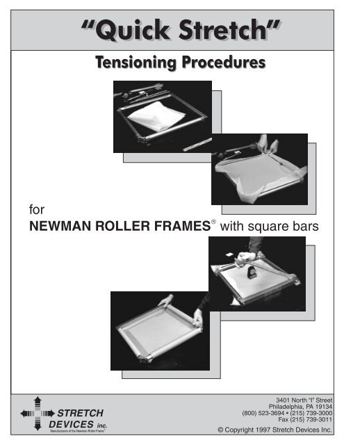
NEWMAN ROLLER FRAMES ®<br />
“QUICK STRETCH”<br />
TENSIONING PROCEDURES<br />
(FOR FRAMES WITH SQUARE BARS)<br />
1.- Frame assembly: The model MZX <strong>Newman</strong> <strong>Roller</strong><br />
Frame ® comes assembled from the factory. The stainless<br />
steel bolts will already have been lubricated with C5A, a<br />
special copper-based anti-seize compound.<br />
2.- Indexing the <strong>Roller</strong>s: Rotate the roller opposite the<br />
square bar so that the outside of the t-slot (closest to you)<br />
is aligned with the first mark on the “inside” top of corner<br />
surface and torque bolts of MZX models to 45 ft/lb.<br />
with a torque wrench. Continuing with the first long roller<br />
(roller #3) rotate so that the outside of the t-slot is aligned<br />
with the second mark on the inside top of corner surface<br />
and torque bolts as before. Repeat the process with the<br />
second long side (roller #4).<br />
FIRST MARK<br />
SECOND<br />
MARK<br />
Why the correct tools are<br />
important: Bolts are secured with<br />
a torque wrench (not just a basic<br />
ratchet wrench). This assures that<br />
the same locking force is applied<br />
to each bolt, keeping the corners<br />
parallel to the table and the frame<br />
flat.<br />
SDI torque wrench: This highest<br />
grade industrial torque wrench has a ½" drive, direction<br />
change lever/button and an audible (click) type action.<br />
The “click” signals the operator to stop moving the<br />
torque wrench against the bolt when the appropriate<br />
torque level has been reached. Moving the direction<br />
change lever/button of the torque wrench to the right will<br />
allow you to tighten the bolts. Moving it to the left will<br />
allow you to loosen the bolts. When not in long term use,<br />
set torque wrench to lowest rating on the primary scale.<br />
SDI Open End Combination Wrench: This magnesium<br />
alloy open end combination wrench is very lightweight,<br />
has an extended handle for better leverage and a wide<br />
grip claw for more surface area coverage on the end plug<br />
and to assure longest life.<br />
High Torque Socket: Our socket is a special 12 point version<br />
with round lobes and can sustain three times the<br />
amount of stress on the head of the bolt without failure.<br />
The 12 points also aid the operator in finding a convenient<br />
placement for the socket.<br />
Stretch Devices, Inc. • Philadelphia, PA, USA • 1-800-523-3694 • (215) 739-3000 • Fax (215) 739-3011 • Page 1
The <strong>Newman</strong> ST Meter: Model 1-E is an industrial grade<br />
measuring device traceable back to the U.S. National<br />
Institute of Standards and Testing, in Washington, DC. It<br />
is the only tension meter in<br />
the world with all six hardened<br />
stainless steel gears, a<br />
shock-proof industrial gear<br />
movement and all jeweled<br />
sapphire bearings. Accuracy<br />
produced is plus or minus<br />
1% across the full scale.<br />
(Other mechanical meters<br />
have only two soft brass gears and bushings, greatly reducing<br />
their shock-resistance, long term accuracy and<br />
life.) When not in use, lay the tension meter on its side, on<br />
its back, or return it to its box.<br />
3.- Preparing the mesh: Cut the edge of the mesh and<br />
rip the remaining way across. This assures that the mesh<br />
is torn on a thread and it is straight. Leave approximately<br />
2–3" of excess mesh around the entire outside dimension<br />
of the frame.<br />
4.- Mesh Insertion: Always insert the mesh<br />
beginning with the square bar.<br />
SQUARE BAR #1<br />
ROLLER #3 ROLLER #4<br />
ROLLER #2<br />
Square Bar, #1: Lay the mesh over the frame and<br />
insert 2 Alignment Clips at each end of the t-slot,<br />
Use the locking strip as a measuring device. Measure the<br />
fabric distance from the Alignment Clip to the “torn”<br />
edge of the mesh. Make this distance approximately<br />
equal on each end (leaving 2" to 3" of excess mesh). Insert<br />
locking strip from right to left. With one hand, pull<br />
gently on the mesh against the Alignment Clips, opposite<br />
the direction of mesh insertion. This assures that the<br />
thread alignment remains straight.<br />
Remove the Alignment<br />
Clip(s)<br />
when the locking<br />
strip reaches each<br />
clip. Do not slide<br />
or push the clips<br />
along with the<br />
locking strip!<br />
NOTE: The reason for measuring approximately equal<br />
distances at both sides of the square bar is to have the<br />
threads parallel and perpendicular to each side of the<br />
frame and for the mesh to be positioned squarely in the<br />
frame.<br />
<strong>Roller</strong> (short) #2: This is the roller opposite the square<br />
bar. Gently pulling the mesh toward you, insert 3 Alignment<br />
Clips: one at each end of the t-slot, and the third<br />
clip in the center. Insert locking strip, from right to left. (If<br />
while inserting the clips, you pulled the mesh with too<br />
much force, the locking strip will not slide easily through<br />
approximately 1" from either end of the square bar.<br />
Stretch Devices, Inc. • Philadelphia, PA, USA • 1-800-523-3694 • (215) 739-3000 • Fax (215) 739-3011 • Page 2
the t-slot. If this occurs, remove the locking strip and<br />
reinsert the Alignment Clips, pulling the mesh towards<br />
you using less force.) With one hand, pull gently on the<br />
mesh against the Alignment Clips, opposite the direction<br />
of mesh insertion.<br />
Remove the Alignment<br />
Clip(s)<br />
when the locking<br />
strip reaches each<br />
clip. Do not slide<br />
or push the clips<br />
along with the<br />
locking strip!<br />
<strong>Roller</strong> (long) #3:<br />
Make sure this side of the mesh has also been “torn.”<br />
Gently pull on the mesh and insert only 2 Alignment<br />
Clips in the t-slot, one at each end, approximately 1"<br />
from where the end plug meets the tube portion of the<br />
the Alignment Clips, pulling the mesh towards you<br />
using less force.)<br />
Remove the Alignment<br />
Clip(s)<br />
when the locking<br />
strip reaches each<br />
clip. Do not slide<br />
or push the clips<br />
along with the<br />
locking strip!<br />
5.- Softening the corners: Before tensioning, be sure to<br />
pre-soften the corners! This will prevent the mesh from<br />
tearing during the stretching process.<br />
aluminum roller. Using the locking strip as a measuring<br />
device, measure the fabric distance from the Alignment<br />
Clips to the “torn” edge of the mesh, as you did on the<br />
square bar. Insert locking strip, from right to left. With one<br />
hand, pull gently on the mesh against the Alignment<br />
Clip, opposite<br />
the direction of<br />
mesh insertion.<br />
Remove the Alignment<br />
Clips(s)<br />
when the locking<br />
strip reaches each<br />
clip. Do not slide<br />
or push the clips<br />
along with the locking strip!<br />
a) Cut the plastic yellow softening tool to the same size<br />
as the diagonal of the corner of the frame, rounding<br />
the corners of the cut side to prevent a sharp edge<br />
from tearing the mesh. This will be the correct size for<br />
this frame model.<br />
<strong>Roller</strong> (long) #4: Gently pulling the mesh toward you,<br />
insert 3 Alignment Clips: one at each end of the t-slot,<br />
and the third clip in the center. Insert locking strip, from<br />
right to left, proceeding as before. (Remember, if while<br />
inserting the clips, you pulled the mesh with too much<br />
force, the locking strip will not slide easily through the<br />
t-slot. If this occurs, remove the locking strip and reinsert<br />
Stretch Devices, Inc. • Philadelphia, PA, USA • 1-800-523-3694 • (215) 739-3000 • Fax (215) 739-3011 • Page 3
) Using a marker, draw a reference line against the<br />
interior edge of the t-slot, approximately 3" long, at<br />
both ends of each roller and the square bar, for a<br />
total of 8 lines.<br />
c) Place the corner softening tool up against the corner<br />
of the frame, positioning it where the endplug meets<br />
the corner. Carefully place an Alignment Clip in the<br />
t-slot at the far end of the softening tool, using it as a<br />
measuring guide. The clip assures that only the Stress<br />
Concentration Zone of the mesh will be softened,<br />
allowing for the greatest possible printing image size.<br />
Repeat this procedure on both sides of the corner.<br />
Follow this procedure on the other side of the same<br />
corner and then proceed to the remaining corner of<br />
the same roller. Release approximately equal amounts<br />
of mesh from each roller, on each side of each corner<br />
opposite the square bar. This serves as an initial softening<br />
guide. Actual distance will depend on the mesh<br />
count and the final tension level.<br />
d) Beginning with one of the corners of the roller opposite<br />
the square bar, and with the corner softening tool<br />
in the t-slot, press down on the inside edge of the<br />
locking strip. Gently rock the tool back and forth,<br />
moving it up and down as if you were cutting carrots,<br />
but always maintaining a pivot point at the clip, in<br />
continuous contact with the mesh. At the same time<br />
with the thumb or 2 fingers of your other hand, push<br />
down on the mesh with constant pressure, until the<br />
mesh touches the table.<br />
e) Continue with one side of the square bar. Position<br />
the softening tool at the end of the square bar, carefully<br />
placing an Alignment Clip in the t-slot at the<br />
far end of the bar. It is not necessary to soften these<br />
corners as much as the corners on the opposing roller<br />
because the square bar doesn’t move.<br />
f) Go now to the other side of the square bar and repeat<br />
the same process.<br />
6.- Calibrating the <strong>Newman</strong> ST Meter:<br />
Place the tension meter on the calibration glass. The tip of<br />
the needle must be exactly aligned with the registration<br />
mark. If the needle is not in the correct position, loosen<br />
the lock on the upper right side of the meter face and<br />
rotate the rim of the face until the needle is correctly<br />
aligned. Retighten the lock. With your fingers on the base<br />
of the tension meter, on either side of the dial face, check<br />
for any rocking motion on the glass that may affect the<br />
movement of the needle. If there is excessive rocking, or if<br />
it is necessary to rotate the dial face more than 15 degrees<br />
to correctly align the needle at the registration mark, the<br />
meter needs to be returned to the factory for recalibration.<br />
Incorrect alignment<br />
of needle<br />
to registration mark.<br />
Correct alignment<br />
of needle<br />
to registration mark.<br />
Stretch Devices, Inc. • Philadelphia, PA, USA • 1-800-523-3694 • (215) 739-3000 • Fax (215) 739-3011 • Page 4
7.- Tensioning the Mesh: Begin by consulting the mesh<br />
tensioning chart to determine initial tension level for your<br />
mesh. Be sure you are consulting the appropriate chart for<br />
the mesh type that you are using.<br />
Note: Stretch Devices provides two different mesh tensioning<br />
charts: one for standard high quality monofilament<br />
polyester fabrics (conventional mesh) and another<br />
for ultra high tension and minimum off-contact distance<br />
<strong>Newman</strong> <strong>Roller</strong> Mesh ® .<br />
Elevate the corners of the frame using four pieces of<br />
squeegee. This will permit free movement of the tools and<br />
keep the mesh off the table.<br />
Begin with the roller opposite the square bar calling it<br />
roller #2. With the torque wrench, loosen each bolt of<br />
this roller two turns. Place the SDI open end wrench on<br />
the endplug, with the wrench perpendicular to the roller.<br />
(An abbreviated version of each of those charts is provided<br />
with these instructions as a quick reference. See<br />
pages 13 and 14.)<br />
With your hand at the top of the open end wrench, move<br />
the wrench in the direction of the square bar to the lowest<br />
position possible. Maintaining this position on the<br />
open end wrench, use the torque wrench in your other<br />
hand to re-torque the bolts.<br />
Standard, conventional mesh tension chart<br />
<strong>Newman</strong> <strong>Roller</strong> Mesh ® Tension Chart<br />
Stretch Devices, Inc. • Philadelphia, PA, USA • 1-800-523-3694 • (215) 739-3000 • Fax (215) 739-3011 • Page 5
Continue with either of the two long rollers, calling it<br />
roller #3. The last remaining roller will be roller #4. Place<br />
the tension meter in the center of the screen. The arrows<br />
on the base of the meter should be pointing between<br />
rollers #3 and #4, in order to correctly read the screen<br />
tension generated when roller #3 is rotated.<br />
Unlock the bolts with the torque wrench and using the<br />
SDI open end combination wrench to rotate the roller,<br />
rotate the roller until you read 50% of the initial tensioning<br />
level on the dial face of the tension meter. Retorque<br />
the bolts, as before.<br />
However, based on these readings, you may want to increase<br />
or decrease the rotation for the roller opposite the<br />
square bar for your next screen. In this way, all of your<br />
mesh counts will have a specific calibration and can be<br />
documented in writing for future use.<br />
IMPORTANT: Check tension not only in the center of the<br />
screen but throughout the print area of your screen, making<br />
sure to include the outside corners. Check both directions<br />
of the mesh. You are looking for consistency within<br />
2 N/cm. If this is not the case, the only way to correct the<br />
problem is through more careful and precise mesh insertion.<br />
After Completing the Initial Tensioning Process: Using a<br />
marker at one corner of the mesh, write the mesh count<br />
and indicate the time and tension level now.<br />
Continue with the last roller #4. Before using the torque<br />
wrench to loosen the second bolt on this roller, be sure to<br />
place the SDI open end combination wrench on the<br />
endplug to prevent the roller from rotating backwards.<br />
Tension the mesh to 100% of the initial tension level.<br />
8.- Verifying that the frames are flat: Elevate the frame<br />
using pieces of squeegee below each corner. To check if<br />
the frame is flat, use your hands to tap lightly across the<br />
diagonal corners for any rocking movement.<br />
With the tension meter still in the center of the screen,<br />
turn the meter 90 degrees, with the arrows on the meter<br />
base pointing between the long rollers. Verify that the<br />
tension levels are equal in both directions, with a difference<br />
of no more than 2 N/cm between them. It is not<br />
necessary to undo the fabric and start over if the tension<br />
varies more than 2 N/cm because when it is time to<br />
retension the screen, the direction that is lowest will be<br />
the only side turned.<br />
Stretch Devices, Inc. • Philadelphia, PA, USA • 1-800-523-3694 • (215) 739-3000 • Fax (215) 739-3011 • Page 6
In the photo below, the left corner is elevated. The frame<br />
is not flat. Go to the corner diagonally opposite the elevated<br />
corner and unlock one bolt.<br />
When the frame is flat, maintaining constant pressure on<br />
the open end wrench, lock the bolt once again with the<br />
torque wrench. Now you can be assured that the frame is<br />
as flat as the surface used for tensioning.<br />
To flatten the frame, put the SDI open end wrench on the<br />
endplug at the far right side of the roller, positioned at<br />
the lowest possible angle.<br />
Placing your left hand at the far end of the SDI open end<br />
wrench, apply downward pressure, until the corner previously<br />
elevated is now flat, and relock the bolt. The downward<br />
pressure on the roller will true the frame to the table<br />
top used for tensioning. The roller will not turn during<br />
this flattening process because the bolt on the other side<br />
of the roller is still torqued and locked. If excessive pressure<br />
is applied to the open end wrench, the corner on the<br />
other side of the roller will rise.<br />
To verify if the tensioning surface is flat: With the square<br />
bar and the 2 corners of the frame simultaneously touching<br />
the table, rotate the frame 90 degrees. If the square<br />
bar and the 2 corners are still touching the table, the<br />
tensioning surface is flat. Check several locations to verify<br />
if the entire surface is flat.<br />
9.- Retensioning the mesh: (Wait a minimum of 20–30<br />
minutes between retensionings.) Place the tension meter<br />
on the mesh in the center of the frame. Check the tension<br />
level in both directions of the mesh.<br />
If in one direction, the tension is lower than in the other,<br />
this determines the direction that requires retensioning.<br />
Once making this determination, choose the roller that<br />
has been turned less.<br />
Stretch Devices, Inc. • Philadelphia, PA, USA • 1-800-523-3694 • (215) 739-3000 • Fax (215) 739-3011 • Page 7
VERY IMPORTANT: Before retensioning, always check the<br />
corners to see if they require additional softening. Only<br />
the corners nearest the roller to be turned need to be soft.<br />
If you continue tensioning the mesh past this point, the<br />
needle on the tension meter will begin to move again but<br />
you will have taken the mesh past the stall point and are<br />
likely to experience premature mesh failure.<br />
While checking for meter stall, be sure that the bolts on<br />
the roller that you are turning have been loosened<br />
enough so that they do not lock up and give you a false<br />
stall point.<br />
If necessary, they can be post-softened at this time.<br />
<strong>Newman</strong> <strong>Roller</strong> Frame ® Mesh Calibration Chart.<br />
With this form you can record the calibration data (starting<br />
position, roller rotation, etc.) for each frame size and<br />
mesh count, to have a permanent tensioning record for<br />
reference and training purposes. (See page 12.)<br />
Once again, place the tension meter on the mesh, in the<br />
center of the frame, to read in the direction you will be<br />
retensioning. Turn the roller until you reach the next tension<br />
level determined by the appropriate mesh tensioning<br />
chart, or to a level determined by you, for your specific<br />
shop requirements. This same procedure can be followed<br />
for subsequent retensionings.<br />
Meter Stall: When determining tension levels for any<br />
given mesh count, it is important not to exceed the elastic<br />
memory of the polyester fibers.<br />
During tensioning, you can see a direct relationship between<br />
the movement of your hand on the open end<br />
wrench and the movement of the needle on the tension<br />
meter. As you continue to move the wrench, you will<br />
reach a point where the needle on the tension meter<br />
appears to hesitate, or stall. Do not continue tensioning<br />
the mesh beyond this level!<br />
Stretch Devices, Inc. • Philadelphia, PA, USA • 1-800-523-3694 • (215) 739-3000 • Fax (215) 739-3011 • Page 8
Note: After you have completed tensioning your frame,<br />
each roller must be rotated a minimum distance, to avoid<br />
the printing problems that would be created by unequal<br />
off-contact distances. The interior edge of the t-slot must<br />
be turned at least as far as the first line on the inside top<br />
surface of the corner.<br />
Inadequate roller rotation<br />
Taping the (inside of) the Frame: Stretch Devices makes<br />
available 2 different specialty tapes used for taping the<br />
inside of the <strong>Newman</strong> <strong>Roller</strong> Frame ® . When used in conjunction<br />
with the <strong>Newman</strong> <strong>Roller</strong> Frame ® , both of these<br />
tapes allow the printer to take advantage of the mesh<br />
flexing from the outside of the frame, maximizing free<br />
mesh area and minimizing print distortion and increasing<br />
usable print space. Regular tapes restrain the mesh during<br />
printing, reducing the free mesh area to the inside dimension<br />
of the <strong>Newman</strong> <strong>Roller</strong> Frame ® .<br />
The <strong>Newman</strong> Split-Liner Solvent Resistant Tape is available<br />
in a clear polyester or brown polypropylene and both<br />
offer superior adhesive structures. This tape was designed<br />
with a dual purpose. It can be used on the inside edge of<br />
the <strong>Newman</strong> <strong>Roller</strong> Frame ® as a free floating ink dam, or<br />
in the center of the frame to separate 2 different inks.<br />
To apply, remove one side of the split-liner from the half<br />
of the tape that will adhere to the mesh. Leave the other<br />
side of the liner intact on the vertical leg of the tape, directly<br />
in front of the roller or box beam. The tape and mesh<br />
are then free to move up and down with the squeegee.<br />
Adequate roller rotation<br />
Preparing the Stretched <strong>Frames</strong> for Use<br />
Trimming the Mesh: After final tensioning or retensioning<br />
of the mesh, you will want to trim the excess mesh down<br />
to 1" (2–3 cm), except in the area around the corners. In<br />
the area closest to the corners you will want to leave additional<br />
mesh (cut here on an angle away from the roller).<br />
By trimming the mesh in this way you can be certain to<br />
have enough mesh available at the corners to permit<br />
post-softening of the corners during future retensionings.<br />
<strong>Newman</strong> <strong>Roller</strong> Tape is a linerless version of the original<br />
split liner tape. The Purple <strong>Roller</strong> Tape is a softer, more<br />
elastic, inert polyethylene substrate with a more aggressive<br />
adhesive. The Teal (Green) <strong>Roller</strong> Tape is a stiffer, less<br />
elastic, inert polyethylene substrate with a more aggressive<br />
adhesive. This tape is unique in that the center section<br />
of the tape has no adhesive. The top section of the<br />
tape has a thin band of adhesive that attaches continuously<br />
along the top of the roller, blocking all ink seepage<br />
along that edge, while still providing a minimum of adhesive<br />
contact for both quick release and some stretching<br />
ability (allowing unrestrained mesh movement during the<br />
squeegee stroke). The bottom section has a wider band of<br />
adhesive that applies directly to the mesh.<br />
Stretch Devices, Inc. • Philadelphia, PA, USA • 1-800-523-3694 • (215) 739-3000 • Fax (215) 739-3011 • Page 9
After cutting the tape to the correct size for the inside of<br />
the frame, apply the bottom section with the wider band<br />
of adhesive to the mesh first, as close to the roller as possible.<br />
Tuck the center section (without adhesive) in between<br />
the mesh and the roller. The top section of the<br />
tape is then applied directly to the roller.<br />
<strong>Newman</strong> Fabric Protectors are plastic covers that fit<br />
around the roller or box beam to protect the mesh. They<br />
are impervious to solvents and inks. They simply slip on<br />
the roller or box-beam and are held in place by tape.<br />
Attaching the fabric protectors.<br />
Because no adhesive is in direct contact with the roller,<br />
free mesh area will be maximized, print distortion minimized<br />
and usable print area will be increased.<br />
The choice of which tape is best for your printing application<br />
is determined by personal preference. You will need<br />
to determine which adhesive offers superior resistance to<br />
your ink and which tape is easiest to use during application.<br />
With any of these tapes, be sure to burnish down that part<br />
of the tape that comes in direct contact with the mesh to<br />
assure a good, positive seal. These tapes are easy to remove<br />
after the print run is complete. After reclaiming, apply tape<br />
again before the next print run, after retensioning.<br />
Finished frame.<br />
Stretch Devices, Inc. • Philadelphia, PA, USA • 1-800-523-3694 • (215) 739-3000 • Fax (215) 739-3011 • Page 10
Clamping into Press or Hand Table: Clamp Adapters for<br />
the <strong>Newman</strong> <strong>Roller</strong> Frame ® are available and recommended<br />
for a wide variety of frame models. The adapter<br />
conforms to the roller on the inside and presents a flat<br />
clamping surface on the top. Where required, they assure<br />
positive lock-down of the frame into the press or hand<br />
table.<br />
The illustration provided below provides a close-up view<br />
of a clamp adapter in the correct position over the roller.<br />
When loading the frame into position place clamp adapters<br />
on the roller approximately positioned where the<br />
swivel pads will be. Once clamped into place, the frame<br />
is positively locked.<br />
On an MZX frame with square bar, when used in a<br />
hand table with hinge clamps or with a rear clamping<br />
machine, the square bar provides a direct clamping surface.<br />
No clamp adapters are needed. This model frame<br />
has no rear corners which provides excellent front end<br />
stability as well as rigidity for raising and lowering.<br />
No clamp adapters are needed in machines outfitted with<br />
<strong>Newman</strong> Pin-Registration System Level 1A Frame Clamping<br />
Channels with Frame Clamping Air Bars.<br />
No clamp adapters are needed with box beam frames.<br />
In a side clamping machine, or front to rear clamping<br />
machine, generally 4 clamp adapters are required per<br />
print head. The long leg of the clamp adapter must be to<br />
the outside to lock effectively. The clamp adapter provides<br />
a flat area for the swivel pad to bear onto, which in turn,<br />
transfers its load to the roller.<br />
REMEMBER: You are using a retensionable <strong>Newman</strong><br />
<strong>Roller</strong> Frame ® . The primary function of a retensionable<br />
frame is to work-harden and stabilize the mesh in order<br />
to provide you and your customers with consistent,<br />
reliable, repeatable results. Utilize the frames in this<br />
manner to achieve superior registration, productivity,<br />
and rapid R.O.I. (return on investment) for this most<br />
important of all quality control printing tools.<br />
TO OBTAIN THE MAXIMUM BENEFITS FROM YOUR<br />
RETENSIONABLE NEWMAN ROLLER FRAMES ® : we recommend<br />
reclaiming your mesh and repeating the process<br />
of retensioning after each production run if the<br />
tension has dropped more than 2N/cm.<br />
Stretch Devices, Inc. • Philadelphia, PA, USA • 1-800-523-3694 • (215) 739-3000 • Fax (215) 739-3011 • Page 11
<strong>Newman</strong> <strong>Roller</strong> Frame ®<br />
Mesh Calibration Chart for <strong>Frames</strong> with Square Bar<br />
for initial screen tension<br />
Frame Model & Size ______________________________________<br />
Mesh count ____________________<br />
Starting Position: <strong>Roller</strong> # 2 _____________________________________<br />
Starting Position: <strong>Roller</strong> # 3 & 4 __________________________________<br />
All bolts torqued to ______________ft. lbs. before tensioning<br />
Square Bar<br />
<strong>Roller</strong> #3 ____________<br />
<strong>Roller</strong> #4 ____________<br />
<strong>Roller</strong> #2 ____________<br />
Insert mesh beginning with square bar — use 2 Alignment Clips.<br />
Go to opposite roller (roller #2) — use 3 Alignment Clips.<br />
Proceed to 1st long roller #3 — use 2 clips.<br />
2nd long roller #4 — use 3 clips.<br />
Use marker or pencil against inside edge of roller to draw a line approx. 3″ long, at end of roller.<br />
Soften corners as required.<br />
Tension screen, turning rollers as indicated.<br />
At the corner of frame, use marker or pencil on mesh to make a time and tension chart.<br />
1st 2nd 3rd<br />
time<br />
tension<br />
Wait 30 minutes before retensioning.<br />
Complete a mesh calibration chart for each mesh count and each frame size.<br />
Stretch Devices, Inc. • Philadelphia, PA, USA • 1-800-523-3694 • (215) 739-3000 • Fax (215) 739-3011 • Page 12
Stretch Devices, Inc. • Philadelphia, PA, USA • 1-800-523-3694 • (215) 739-3000 • Fax (215) 739-3011 • Page 13<br />
Screen Tension & Work Hardening Chart<br />
for Standard High-Quality Monofilament Polyester Fabrics<br />
Threads Threads per Thread % Open Initial First Second Retensioning Average Tension Average Tension Average Tension<br />
per inch centimeter Diameter Area Tensioning Retensioning Retensioning after 1st Print Run LOSS after LOSS after LOSS after each<br />
(microns) N/cm N/cm N/cm N/cm 1st Print Run* 2nd Print Run* Subsequent<br />
N/cm N/cm Print Run<br />
N/cm<br />
38 15 260 37% 40 50 60 70–85 12 4 4<br />
60 24 145 41% 34 40 45 48–68 16 5 4<br />
74 29 120 40% 34 40 45 48–68 16 5 4<br />
86 34 100 43% 32 36 40 45–58 16 5 3<br />
110 43 80 42% 28 32 36 38–45 12 6 3<br />
137 54 73 35% 28 32 36 38–46 12 6 3<br />
156 62 66 34% 25 29 33 34–42 12 5 2.5<br />
180 71 55 36% 24 28 32 34–45 12 5 2.5<br />
196 77 55 32% 20 24 28 28–42 12 5 2.5<br />
230 90 48 32% 18 22 26 28–34 12 6 3<br />
230 90 55 25% 22 28 34 38–48 10 4 2.5<br />
255 100 40 36% 14 16 17 17–20 8 5 3.5<br />
260 102 38 36% 14 16 17 17–20 7 4 3<br />
280 110 40 30% 14 18 20 24–28 5 3 2<br />
305 120 35 37% 14 18 22 22–26 7 4 3<br />
305 120 40 27% 16 20 24 26–34 7 3 2<br />
355 140 35 23% 16 18 22 22–26 6 3 2<br />
390 154 33 24% 14 16 18 18–22 6 4 3<br />
390 154 35 21% 16 18 22 22–28 4 3 2<br />
420 165 30 23% 14 16 18 18–22 6 4 2<br />
420 165 33 19% 16 18 20 24–27 4 2 2<br />
For additional information, ask for Tension Chart #9.<br />
Allow screen to relax ½ to 2 hours.<br />
Allow screen to relax ½ to 2 hours.<br />
← Third retensioning — optional →<br />
*Average tension losses shown above may occur<br />
only at maximum screen tension. Smaller tension<br />
losses will occur at lower tension levels.<br />
Manufacturers of <strong>Newman</strong> <strong>Roller</strong> Frame ® , the original self-tensioning and work hardening machine.<br />
© Stretch Devices, Inc. 1990 All rights reserved.<br />
Philadelphia, PA, USA • 1-800-523-3694 • (215) 739-3000 • Fax (215) 739-3011
Stretch Devices, Inc. • Philadelphia, PA, USA • 1-800-523-3694 • (215) 739-3000 • Fax (215) 739-3011 • Page 14<br />
Screen Tensioning and Work-Hardening Chart<br />
for use with <strong>Newman</strong> <strong>Roller</strong> Mesh ®<br />
for use with <strong>Newman</strong> <strong>Roller</strong> Mesh ® on <strong>Newman</strong> <strong>Roller</strong> <strong>Frames</strong> ®<br />
Tension <strong>Newman</strong> <strong>Roller</strong> Mesh ® between 70% of Maximum to Maximum Newton/cm<br />
Higher Strength Filaments Engineered for 100 Newton Printing<br />
Maximum Mesh Initial One to Two Retensioning after Retensioning after<br />
Recommended Count Tensioning Retensioning First Print Run Second Print Run<br />
Tension Nominal N/cm Before Printing N/cm N/cm<br />
N/cm (th/in) (th/cm) 70%–Max. N/cm 70%–Max. 70%–Max.<br />
Tension Range 70%–Max. Tension Range Tension Range<br />
Tension Range<br />
pul. cm.<br />
120 N70 N27 55–75 60–85 70–100 70–120<br />
110 N88 N34 48–65 56–80 62–90 70–110<br />
Screen only needs to relax<br />
20 to 30 minutes before retensioning<br />
90 N115 N45 45–65 56–80 58–85 62–90<br />
80 N138 N54 42–60 50–75 52–75 56–80<br />
85 N166 N65 42–60 49–70 52–75 58–85<br />
74 N205 N81 40–55 46–65 47–68 50–74<br />
82 N228 N90 45–60 52–75 56–80 57–82<br />
65 N272 N107 36–48 40–58 44–62 46–65<br />
70 N300 N118 38–50 42–60 45–65 49–70<br />
60 N380 N150 32–45 36–52 40–56 42–60<br />
Note: The “N” before the mesh number signifies <strong>Newman</strong> <strong>Roller</strong> Mesh ®<br />
For more information, ask for the complete Chart for use with <strong>Newman</strong> <strong>Roller</strong> Mesh ® by saati on <strong>Newman</strong> <strong>Roller</strong> <strong>Frames</strong> ®<br />
← Third Retensioning — Optional →<br />
← First Print Run and Reclaiming →<br />
(Fabric receives full cycle of<br />
chemicals and squeegee pressure)<br />
Manufacturers of the <strong>Newman</strong> <strong>Roller</strong> Frame ®<br />
Direct Importers of <strong>Newman</strong> <strong>Roller</strong> Mesh ®<br />
© Stretch Devices, Inc. 1991 All Rights Reserved<br />
Philadelphia, PA, USA • 1-800-523-3694 • (215) 739-3000 • Fax (215) 739-3011