Lampak UFO-7W-I Installation Instructions - Dual-Lite
Lampak UFO-7W-I Installation Instructions - Dual-Lite
Lampak UFO-7W-I Installation Instructions - Dual-Lite

You also want an ePaper? Increase the reach of your titles
YUMPU automatically turns print PDFs into web optimized ePapers that Google loves.
INSTALLATION<br />
WARNING: TO PREVENT HIGH VOLTAGE from being present on red and yellow<br />
output leads prior to installation, inverter connector must be open. do<br />
not join inverter connector until installation is complete and ac power<br />
is supplied to the emergency ballast.<br />
NOTE: Before installing the emergency ballast, make sure that the necessary branch circuit wiring is<br />
available. An unswitched source of power is required. The emergency ballast must be fed from the<br />
same branch circuit as the AC ballast.<br />
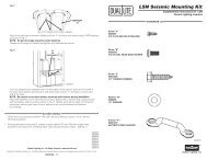
1. Disconnect AC power from the fixture. Install the emergency ballast either on top of the fixture (see Illustration<br />
1) or remote from the fixture up to 1/2 the distance the AC ballast manufacturer recommends remoting the AC<br />
ballast from the lamp, or up to 50 feet, whichever is less (see Illustration 2).<br />
2. Select the appropriate wiring diagram to connect the emergency<br />
ballast to the AC ballast and lamp. Make sure all connections are ILLUSTRATION 1<br />
in accorance with the National Electrical Code and any local<br />
regulations.<br />
3. Install the test switch through the ballast channel cover of a<br />
troffer or through the side of a strip fixture. Drill a 1/2" hole and<br />
install the test switch as shown (see Illustration 3). Wire the<br />
test switch so that it removes AC power from both the emergency<br />
ballast and the AC ballast at the same time (see wiring<br />
diagrams).<br />
4. Refer to Illustration 3 and install the charging indicator<br />
light. Connect charging indicator light to emergency ballast by<br />
matching violet and brown leads.<br />
5. In a readily visible location, attach the label "CAUTION-This Unit<br />
Has More Than One Power Connection Point. To Reduce The<br />
Risk Of Electric Shock, Disconnect Both The Branch Circuit-<br />
Breakers Or Fuses And Emergency Power Supplies Before Servicing."<br />
ILLUSTRATION 2<br />
rEMOTE INSTALLATION<br />
Fixture<br />
1/2 the distance recommended<br />
by the AC ballast manufacturer,<br />
or up to 50 feet, whichever is less<br />
Junction<br />
Box<br />
2' conduit<br />
provided<br />
NOTE: Do not extend inverter connector leads (white and red), and lamp selector (brown) leads. These<br />
connectors should be left in the junction box.<br />
1 Emergency ballast with flexible conduit.<br />
2 Conduit and junction box (not supplied), but necessary for remote installation.<br />
Emergency<br />
Ballast<br />
6. After installation is complete, supply AC power to the emergency ballast and join the inverter connector.<br />
7. A short-term discharge test may be conducted after the emergency ballast has been charging for one hour.<br />
Charge for 24 hours before conducting a long-term discharge test. Refer to OPERATION.<br />
8. To disarm audible alarm, cut red/white wire loop (CAP ENDS).<br />
2