Lampak UFO-7W-I Installation Instructions - Dual-Lite
Lampak UFO-7W-I Installation Instructions - Dual-Lite
Lampak UFO-7W-I Installation Instructions - Dual-Lite

Create successful ePaper yourself
Turn your PDF publications into a flip-book with our unique Google optimized e-Paper software.
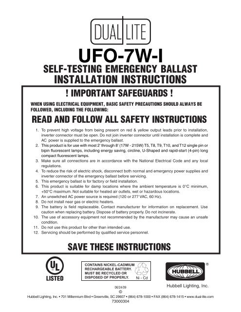
<strong>UFO</strong>-<strong>7W</strong>-I<br />
SELF-TESTING EMERGENCY BALLAST<br />
INSTALLATION INSTRUCTIONS<br />
! IMPORTANT SAFEGUARDS !<br />
WHEN USING ELECTRICAL EQUIPMENT, BASIC SAFETY PRECAUTIONS SHOULD ALWAYS BE<br />
FOLLOWED, INCLUDING THE FOLLOWING:<br />
READ AND FOLLOW ALL SAFETY INSTRUCTIONS<br />
1. To prevent high voltage from being present on red & yellow output leads prior to installation,<br />
inverter connector must be open. Do not join inverter connector until installation is complete and<br />
AC power is supplied to the emergency ballast.<br />
2. This product is for use with most 2' through 8' (1<strong>7W</strong> - 215W) T5, T8, T9, T10, and T12 single pin or<br />
bipin fluorescent lamps, including energy saving, circline, U-Shaped and rapid-start (4-pin) long<br />
compact fluorescent lamps.<br />
3. Make sure all connections are in accordance with the National Electrical Code and any local<br />
regulations.<br />
4. To reduce the risk of electric shock, disconnect both normal and emergency power supplies and<br />
inverter connector of the emergency ballast before servicing.<br />
5. This emergency ballast is for factory or field installation.<br />
6. This product is suitable for damp locations where the ambient temperature is 0°C minimum,<br />
+50°C maximum. Not suitable for heated air outlets, wet or hazardous locations.<br />
7. An unswitched AC power source is required (120 or 277 VAC, 60 Hz).<br />
8. Do not install near gas or electric heaters.<br />
9. The battery is field replaceable. Contact manufacturer for information on replacement. Use<br />
caution when replacing battery. Dispose of battery properly. Do not incinerate.<br />
10. The use of accessory equipment not recommended by the manufacturer may cause an unsafe<br />
condition.<br />
11. Do not use this product for other than intended use.<br />
12. Servicing should be performed by qualified service personnel.<br />
SAVE THESE INSTRUCTIONS<br />
CONTAINS NICKEL-CADMIUM<br />
RECHARGEABLE BATTERY.<br />
MUST BE RECYCLED OR<br />
DISPOSED OF PROPERLY.<br />
Ni - Cd<br />
HUBBELL<br />
Hubbell Lighting, Inc.<br />
06/24/09<br />
©<br />
Hubbell Lighting, Inc. • 701 Millennium Blvd • Greenville, SC 29607 • (864) 678-1000 • FAX (864) 678-1415 • www.dual-lite.com<br />
73000304<br />
®
INSTALLATION<br />
WARNING: TO PREVENT HIGH VOLTAGE from being present on red and yellow<br />
output leads prior to installation, inverter connector must be open. do<br />
not join inverter connector until installation is complete and ac power<br />
is supplied to the emergency ballast.<br />
NOTE: Before installing the emergency ballast, make sure that the necessary branch circuit wiring is<br />
available. An unswitched source of power is required. The emergency ballast must be fed from the<br />
same branch circuit as the AC ballast.<br />
1. Disconnect AC power from the fixture. Install the emergency ballast either on top of the fixture (see Illustration<br />
1) or remote from the fixture up to 1/2 the distance the AC ballast manufacturer recommends remoting the AC<br />
ballast from the lamp, or up to 50 feet, whichever is less (see Illustration 2).<br />
2. Select the appropriate wiring diagram to connect the emergency<br />
ballast to the AC ballast and lamp. Make sure all connections are ILLUSTRATION 1<br />
in accorance with the National Electrical Code and any local<br />
regulations.<br />
3. Install the test switch through the ballast channel cover of a<br />
troffer or through the side of a strip fixture. Drill a 1/2" hole and<br />
install the test switch as shown (see Illustration 3). Wire the<br />
test switch so that it removes AC power from both the emergency<br />
ballast and the AC ballast at the same time (see wiring<br />
diagrams).<br />
4. Refer to Illustration 3 and install the charging indicator<br />
light. Connect charging indicator light to emergency ballast by<br />
matching violet and brown leads.<br />
5. In a readily visible location, attach the label "CAUTION-This Unit<br />
Has More Than One Power Connection Point. To Reduce The<br />
Risk Of Electric Shock, Disconnect Both The Branch Circuit-<br />
Breakers Or Fuses And Emergency Power Supplies Before Servicing."<br />
ILLUSTRATION 2<br />
rEMOTE INSTALLATION<br />
Fixture<br />
1/2 the distance recommended<br />
by the AC ballast manufacturer,<br />
or up to 50 feet, whichever is less<br />
Junction<br />
Box<br />
2' conduit<br />
provided<br />
NOTE: Do not extend inverter connector leads (white and red), and lamp selector (brown) leads. These<br />
connectors should be left in the junction box.<br />
1 Emergency ballast with flexible conduit.<br />
2 Conduit and junction box (not supplied), but necessary for remote installation.<br />
Emergency<br />
Ballast<br />
6. After installation is complete, supply AC power to the emergency ballast and join the inverter connector.<br />
7. A short-term discharge test may be conducted after the emergency ballast has been charging for one hour.<br />
Charge for 24 hours before conducting a long-term discharge test. Refer to OPERATION.<br />
8. To disarm audible alarm, cut red/white wire loop (CAP ENDS).<br />
2
ILLUSTRATION 3<br />
troffer style fixture<br />
strip style fixture<br />
Fixture<br />
Fixture<br />
Charging<br />
Indicator<br />
Light<br />
Charging<br />
Indicator<br />
Light<br />
Violet (+)<br />
Violet (+)<br />
Brown (–)<br />
Brown (–)<br />
1/2" White<br />
Bushing<br />
1/2" Punch<br />
5/8" Black<br />
Bushing<br />
1/2" White<br />
Bushing<br />
5/8" Black<br />
Bushing<br />
Emergency Ballast (on top)<br />
Charging Indicator Light<br />
Test Switch<br />
Ballast<br />
Channel<br />
Cover<br />
NOTE: After installing the charging indicator light and test switch, mark each with the appropriate label.<br />
OPERATION<br />
During normal operation, AC power is applied and the self-testing emergency ballast charges the battery. Connecting<br />
the (red and white) inverter connector wires enables the emergency circuit, and supplies power to the control/monitor<br />
circuit and charging indicator light. The self-testing emergency ballast continually monitors the charging current and<br />
battery voltage, comparing them to preset limits. Should the unit detect an unusual current or voltage condition, the<br />
indicator light will flash and the internal audible alarm will sound.<br />
When AC power fails, the self-testing emergency ballast automatically switches to emergency mode, keeping<br />
either one or two lamps illuminated at a reduced lumen output for a minimum of 90 minutes. When AC power<br />
is restored, the self-testing emergency ballast returns to charging mode and delays AC ballast operation for<br />
approximately three seconds to prevent false tripping of AC ballast (end-of-lamp life) shutdown circuits.<br />
SELF-TESTING OPERATION<br />
This unit contains a control/monitor circuit that automatically performs a 30-second discharge test every 30 days, and<br />
a full 90-minute discharge test once a year. During routine testing, the self-testing emergency ballast simulates an AC<br />
power failure causing the unit to automatically switch to emergency mode. The unit will monitor the operation of the<br />
lamps, battery voltage, discharge current, and emergency duration. If the emergency system functions properly, then<br />
the unit will return to normal mode. Should the unit detect any problems, the indicator light will flash continually and<br />
the audible alarm will sound 4 times every 30 seconds until the condition has been corrected or the unit passes the<br />
next test.To reset a failure indication, push and hold the test switch for a minimum of 15 seconds. If the condition has<br />
not been corrected by the next scheduled test, the unit will once again detect the failure and signal the failure indicator.<br />
To cancel a test, turn the wall switch ON (or OFF if switch is already on), wait 5 seconds, then turn it OFF (ON).<br />
MAINTENANCE<br />
This self-testing emergency ballast automatically performs required routine testing. Results are reported to<br />
maintenance personnel via the indicator light and audible alarm.<br />
Note: If optional audible alarm is disabled, maintenance personnel should periodically check the indicator light. If the<br />
indicator light is flashing, go through all steps of Troubleshooting Guide.<br />
3
TROUBLESHOOTING GUIDE<br />
STATUS INDICATORS<br />
INDICATOR<br />
LIGHT<br />
Light on<br />
steady, not<br />
flashing<br />
Flashing 1/2<br />
Second<br />
Intervals<br />
AUDIBLE<br />
ALARM<br />
PROBLEM<br />
CORRECTION<br />
No beeping None Unit is Operating Correctly.<br />
Beeping<br />
1/2<br />
Second<br />
Intervals<br />
Line voltage;<br />
incorrect<br />
installation<br />
Battery voltage<br />
is outside limits.<br />
Check line voltage. For 120 VAC use black as hot;<br />
for 277 VAC use orange as hot wire lead.<br />
Let battery charge. If after an hour failure is still<br />
indicated, see action below.<br />
Flashing<br />
1/2<br />
Second<br />
Intervals<br />
Beeping<br />
4 times<br />
every 30<br />
seconds<br />
Failed scheduled<br />
self-test<br />
1. Check to make sure lamps are good<br />
(operational and specified for self-testing<br />
emergency ballast) and in place.<br />
2. Check to see if brown connector is properly used. (See<br />
Table 1.)<br />
3. Check that fixture wiring is in accordance with proper wiring<br />
diagram.<br />
4. Allow unit to charge for 24 hours. Perform manual test. If<br />
flashing/beeping continue, emergency ballast should be<br />
replaced.<br />
Any other erroneous status<br />
indications<br />
Corrupted chip<br />
memory<br />
Open inverter connector (red and white wires)<br />
and push manual test switch for 15 seconds<br />
minimum, then reconnect battery connector.<br />
Failure Satus will be reset when the unit passes:<br />
•<br />
•<br />
•<br />
The next automatic test, or<br />
A manual test exceeding 15 seconds, or<br />
An actual power failure exceeding 15 seconds.<br />
NOTE: It is normal for the indicator light to remain off for a few minutes on<br />
initial start-up or after a very long power outage (discharge), as the battery<br />
voltage rises to normal range. Refer to the Troubleshooting Guide if this<br />
condition persists.<br />
4
WIRING DIAGRAMS<br />
EMERGENCY BALLAST AND AC BALLAST MUST BE FED FROM THE SAME BRANCH CIRCUIT.<br />
TYPICAL SCHEMATICS ONLY. MAY BE USED WITH OTHER BALLASTS. CONSULT THE FACTORY FOR OTHER WIRING DIAGRAMS.<br />
Table 1 - Lamp Compatibility<br />
LAMP DIAMETER<br />
(T8, T9, T10, T12)<br />
1”, 1¼”, 1½”<br />
Long Compact<br />
Twin/Quad<br />
Twin-Tube Compact<br />
2D<br />
T5 (5/8”)<br />
BASE<br />
Single<br />
or<br />
Bipin<br />
4-PIN (2G11)<br />
4-PIN<br />
(G24q, GX24q)<br />
4-PIN<br />
(GR10q)<br />
Bipin<br />
WATTAGE<br />
(Length)<br />
17 - 40 W (2’ - 4’)<br />
NO. of LAMPS BROWN<br />
(EMERGENCY) CONNECTOR<br />
1 CLOSED<br />
2 OPEN<br />
40 - 215 W (5' -8') 1 OPEN<br />
18 - 39 W<br />
1 CLOSED<br />
2 OPEN<br />
40 - 55 W 1 OPEN<br />
18 - 42 W<br />
16 - 38 W<br />
1 CLOSED<br />
2 OPEN<br />
1 CLOSED<br />
2 OPEN<br />
55 W 1 OPEN<br />
14 - 54 W<br />
(2’ - 4’)<br />
1 CLOSED<br />
WIRING DIAGRAMS for 1-LAMP emergency operation<br />
FIG 99. ONE (1) LAMP RAPID START BALLAST<br />
FIG 119. ONE (1) LAMP INSTANT START BALLAST<br />
HOT<br />
TEST<br />
SWITCH<br />
B<br />
L<br />
K<br />
B<br />
L<br />
K<br />
COMMON<br />
WHT/RED<br />
WALL SWITCH<br />
RED<br />
INVERTER<br />
CONNECTOR<br />
WHITE<br />
BUZZER RED/WHT<br />
SELECTOR<br />
CHARGING<br />
VIOLET<br />
INDICATOR<br />
LIGHT<br />
BROWN<br />
BLACK 120V<br />
(CAP UNUSED LEAD) OR<br />
ORANGE 277V<br />
WHITE<br />
WHT/BLK<br />
E<br />
M B<br />
E A<br />
R L<br />
L<br />
G<br />
E<br />
N<br />
C<br />
Y<br />
A<br />
S<br />
T<br />
BROWN<br />
BROWN<br />
RED<br />
YELLOW<br />
YEL/BLK<br />
BLU/WHT<br />
BLUE<br />
WARNING: Refer to Table 1 before connecting<br />
LAMP<br />
BLUE<br />
RED<br />
BLUE<br />
RED<br />
1 LAMP<br />
RAPID<br />
START<br />
BALLAST<br />
BLK<br />
HOT<br />
TEST<br />
SWITCH<br />
B<br />
L<br />
K<br />
B<br />
L<br />
K<br />
COMMON<br />
WHT/RED<br />
WALL SWITCH<br />
RED<br />
INVERTER<br />
CONNECTOR<br />
WHITE<br />
BUZZER RED/WHT<br />
SELECTOR<br />
CHARGING<br />
VIOLET<br />
INDICATOR<br />
LIGHT<br />
BROWN<br />
BLACK 120V<br />
(CAP UNUSED LEAD) OR<br />
ORANGE 277V<br />
WHITE<br />
WHT/BLK<br />
E<br />
M B<br />
E A<br />
R L<br />
L<br />
G<br />
E<br />
N<br />
C<br />
Y<br />
A<br />
S<br />
T<br />
BROWN<br />
BROWN<br />
RED<br />
YELLOW<br />
YEL/BLK<br />
BLU/WHT<br />
BLUE<br />
BLUE<br />
BLK<br />
WARNING: Refer to Table 1 before connecting<br />
LAMP<br />
RED<br />
1 LAMP<br />
INSTANT<br />
START<br />
BALLAST<br />
WHT<br />
WHT<br />
FIG 133. TWO (2) LAMP RAPID START BALLAST<br />
FIG 104. TWO (2) LAMP INSTANT START BALLAST<br />
HOT<br />
TEST<br />
SWITCH<br />
B<br />
L<br />
K<br />
B<br />
L<br />
K<br />
COMMON<br />
WHT/RED<br />
WALL SWITCH<br />
RED<br />
INVERTER<br />
CONNECTOR<br />
WHITE<br />
BUZZER RED/WHT<br />
SELECTOR<br />
CHARGING<br />
VIOLET<br />
INDICATOR<br />
LIGHT<br />
BROWN<br />
BLACK 120V<br />
(CAP UNUSED LEAD) OR<br />
ORANGE 277V<br />
WHITE<br />
WHT/BLK<br />
E<br />
M B<br />
E A<br />
R L<br />
L<br />
G<br />
E<br />
N<br />
C<br />
Y<br />
A<br />
S<br />
T<br />
BROWN<br />
BROWN<br />
RED<br />
YELLOW<br />
YEL/BLK<br />
BLU/WHT<br />
BLUE<br />
WARNING: Refer to Table 1 before connecting<br />
LAMP 1 (EMERGENCY )<br />
BLUE<br />
RED<br />
LAMP 2<br />
BLUE 2 LAMP RED<br />
RAPID<br />
START<br />
BALLAST<br />
BLK<br />
YELLOW<br />
WHT<br />
YELLOW<br />
HOT<br />
TEST<br />
SWITCH<br />
B<br />
L<br />
K<br />
B<br />
L<br />
K<br />
COMMON<br />
WHT/RED<br />
WALL SWITCH<br />
RED<br />
INVERTER<br />
CONNECTOR<br />
WHITE<br />
BUZZER RED/WHT<br />
SELECTOR<br />
CHARGING<br />
VIOLET<br />
INDICATOR<br />
LIGHT<br />
BROWN<br />
BLACK 120V<br />
(CAP UNUSED LEAD) OR<br />
ORANGE 277V<br />
WHITE<br />
WHT/BLK<br />
E<br />
M B<br />
E A<br />
R L<br />
L<br />
G<br />
E<br />
N<br />
C<br />
Y<br />
A<br />
S<br />
T<br />
BROWN<br />
BROWN<br />
RED<br />
YELLOW<br />
YEL/BLK<br />
BLU/WHT<br />
BLUE<br />
WARNING: Refer to Table 1 before connecting<br />
LAMP 1 (EMERGENCY)<br />
LAMP 2<br />
BLUE<br />
BLUE<br />
2 LAMP RED<br />
INSTART<br />
START<br />
BALLAST<br />
BLK<br />
WHT<br />
FIG 105. THREE (3) LAMP RAPID START BALLAST<br />
FIG 106. THREE (3) LAMP INSTANT START BALLAST<br />
HOT<br />
TEST<br />
SWITCH<br />
B<br />
L<br />
K<br />
B<br />
L<br />
K<br />
COMMON<br />
WHT/RED<br />
WALL SWITCH<br />
RED<br />
INVERTER<br />
CONNECTOR<br />
WHITE<br />
BUZZER RED/WHT<br />
SELECTOR<br />
CHARGING<br />
VIOLET<br />
INDICATOR<br />
LIGHT<br />
BROWN<br />
BLACK 120V<br />
(CAP UNUSED LEAD) OR<br />
ORANGE 277V<br />
WHITE<br />
WHT/BLK<br />
E<br />
M B<br />
E A<br />
R L<br />
L<br />
G<br />
E<br />
N<br />
C<br />
Y<br />
A<br />
S<br />
T<br />
BROWN<br />
BROWN<br />
RED<br />
YELLOW<br />
YEL/BLK<br />
BLU/WHT<br />
BLUE<br />
WARNING: Refer to Table 1 before connecting<br />
LAMP 1 (EMERGENCY)<br />
BLU/WHT<br />
BLU/WHT<br />
BLUE<br />
YELLOW<br />
LAMP 2<br />
BLUE<br />
YELLOW<br />
3 LAMP<br />
RAPID<br />
LAMP 3<br />
START<br />
BALLAST<br />
BLK<br />
RED<br />
WHT<br />
RED<br />
HOT<br />
TEST<br />
SWITCH<br />
B<br />
L<br />
K<br />
B<br />
L<br />
K<br />
COMMON<br />
WHT/RED<br />
WALL SWITCH<br />
RED<br />
INVERTER<br />
CONNECTOR<br />
WHITE<br />
BUZZER RED/WHT<br />
SELECTOR<br />
CHARGING<br />
VIOLET<br />
INDICATOR<br />
LIGHT<br />
BROWN<br />
BLACK 120V<br />
(CAP UNUSED LEAD) OR<br />
ORANGE 277V<br />
WHITE<br />
WHT/BLK<br />
E<br />
M B<br />
E A<br />
R L<br />
L<br />
G<br />
E<br />
N<br />
C<br />
Y<br />
A<br />
S<br />
T<br />
BROWN<br />
BROWN<br />
RED<br />
YELLOW<br />
YEL/BLK<br />
BLU/WHT<br />
BLUE<br />
WARNING: Refer to Table 1 before connecting<br />
LAMP 1 (EMERGENCY)<br />
LAMP 2<br />
BLUE<br />
BLUE<br />
3 LAMP<br />
INSTANT<br />
LAMP 3<br />
START BLUE<br />
BALLAST RED<br />
BLK<br />
WHT<br />
FIG 120. FOUR (4) LAMP RAPID START BALLAST<br />
FIG 121. FOUR (4) LAMP INSTANT START BALLAST<br />
HOT<br />
TEST<br />
SWITCH<br />
B<br />
L<br />
K<br />
B<br />
L<br />
K<br />
COMMON<br />
WHT/RED<br />
WALL SWITCH<br />
RED<br />
INVERTER<br />
CONNECTOR<br />
WHITE<br />
BUZZER RED/WHT<br />
SELECTOR<br />
CHARGING<br />
VIOLET<br />
INDICATOR<br />
LIGHT<br />
BROWN<br />
BLACK 120V<br />
(CAP UNUSED LEAD) OR<br />
ORANGE 277V<br />
WHITE<br />
WHT/BLK<br />
E<br />
M B<br />
E A<br />
R L<br />
L<br />
G<br />
E<br />
N<br />
C<br />
Y<br />
A<br />
S<br />
T<br />
BROWN<br />
BROWN<br />
RED<br />
YELLOW<br />
YEL/BLK<br />
BLU/WHT<br />
BLUE<br />
WARNING: Refer to Table 1 before connecting<br />
LAMP 1 (EMERGENCY)<br />
YELLOW<br />
YELLOW<br />
RED<br />
LAMP 2<br />
RED<br />
BLU/WHT<br />
4 LAMP BLU/WHT<br />
LAMP 3<br />
RAPID<br />
START BROWN<br />
BALLAST BROWN<br />
BLK<br />
BLUE<br />
WHT<br />
LAMP 4<br />
BLUE<br />
HOT<br />
TEST<br />
SWITCH<br />
B<br />
L<br />
K<br />
B<br />
L<br />
K<br />
COMMON<br />
WHT/RED<br />
WALL SWITCH<br />
RED<br />
INVERTER<br />
CONNECTOR<br />
WHITE<br />
BUZZER RED/WHT<br />
SELECTOR<br />
CHARGING<br />
VIOLET<br />
INDICATOR<br />
LIGHT<br />
BROWN<br />
BLACK 120V<br />
(CAP UNUSED LEAD) OR<br />
ORANGE 277V<br />
WHITE<br />
WHT/BLK<br />
E<br />
M B<br />
E A<br />
R L<br />
L<br />
G<br />
E<br />
N<br />
C<br />
Y<br />
A<br />
S<br />
T<br />
BROWN<br />
BROWN<br />
RED<br />
YELLOW<br />
YEL/BLK<br />
BLU/WHT<br />
BLUE<br />
WARNING: Refer to Table 1 before connecting<br />
LAMP 1 (EMERGENCY)<br />
YELLOW<br />
LAMP 2<br />
BLUE<br />
BLUE<br />
4 LAMP<br />
INSTANT<br />
LAMP 3<br />
START RED<br />
BALLAST<br />
BLK<br />
YELLOW<br />
WHT<br />
LAMP 4<br />
RED<br />
5<br />
06/24/09<br />
70430020
WIRING DIAGRAMS for 1-LAMP emergency operation<br />
FIG 134. ONE (1) LAMP COMPACT RAPID START BALLAST<br />
FIG 135. TWO (2) LAMP COMPACT RAPID START BALLAST<br />
HOT<br />
TEST<br />
SWITCH<br />
B<br />
L<br />
K<br />
B<br />
L<br />
K<br />
COMMON<br />
WHT/RED<br />
WALL SWITCH<br />
RED<br />
INVERTER<br />
CONNECTOR<br />
WHITE<br />
BUZZER RED/WHT<br />
SELECTOR<br />
CHARGING<br />
VIOLET<br />
INDICATOR<br />
LIGHT<br />
BROWN<br />
BLACK 120V<br />
(CAP UNUSED LEAD) OR<br />
ORANGE 277V<br />
WHITE<br />
WHT/BLK<br />
E<br />
M B<br />
E A<br />
R L<br />
L<br />
G<br />
E<br />
N<br />
C<br />
Y<br />
A<br />
S<br />
T<br />
BROWN<br />
BROWN<br />
RED<br />
YELLOW<br />
YEL/BLK<br />
BLU/WHT<br />
BLUE<br />
WARNING: Refer to Table 1 before connecting<br />
LAMP<br />
BLUE<br />
RED<br />
BLUE<br />
RED<br />
1 LAMP<br />
RAPID<br />
START<br />
BALLAST<br />
BLK<br />
WHT<br />
HOT<br />
TEST<br />
SWITCH<br />
B<br />
L<br />
K<br />
B<br />
L<br />
K<br />
COMMON<br />
WHT/RED<br />
WALL SWITCH<br />
RED<br />
INVERTER<br />
CONNECTOR<br />
WHITE<br />
BUZZER RED/WHT<br />
SELECTOR<br />
CHARGING<br />
VIOLET<br />
INDICATOR<br />
LIGHT<br />
BROWN<br />
BLACK 120V<br />
(CAP UNUSED LEAD) OR<br />
ORANGE 277V<br />
WHITE<br />
WHT/BLK<br />
E<br />
M B<br />
E A<br />
R L<br />
L<br />
G<br />
E<br />
N<br />
C<br />
Y<br />
A<br />
S<br />
T<br />
BROWN<br />
BROWN<br />
RED<br />
YELLOW<br />
YEL/BLK<br />
BLU/WHT<br />
BLUE<br />
BLUE<br />
BLUE<br />
BLK<br />
WHT<br />
2 LAMP<br />
RAPID<br />
START<br />
BALLAST<br />
WARNING: Refer to Table 1 before connecting<br />
YELLOW<br />
YELLOW<br />
RED<br />
RED<br />
LAMP 1<br />
( EMERGENCY)<br />
LAMP 2<br />
WIRING DIAGRAMS for 2-LAMP emergency operation (2'-4', 17-40 W lamps only)<br />
FIG 140. TWO (2) LAMP RAPID START BALLAST<br />
FIG 125. TWO (2) LAMP INSTANT START BALLAST<br />
HOT<br />
TEST<br />
SWITCH<br />
B<br />
L<br />
K<br />
B<br />
L<br />
K<br />
COMMON<br />
WHT/RED<br />
WALL SWITCH<br />
RED<br />
INVERTER<br />
CONNECTOR<br />
WHITE<br />
BUZZER RED/WHT<br />
SELECTOR<br />
CHARGING<br />
VIOLET<br />
INDICATOR<br />
LIGHT<br />
BROWN<br />
BLACK 120V<br />
(CAP UNUSED LEAD) OR<br />
ORANGE 277V<br />
WHITE<br />
WHT/BLK<br />
E<br />
M B<br />
E A<br />
R L<br />
L<br />
G<br />
E<br />
N<br />
C<br />
Y<br />
A<br />
S<br />
T<br />
BROWN<br />
BROWN<br />
YELLOW<br />
YEL/BLK<br />
RED<br />
BLU/WHT<br />
BLUE<br />
WARNING: Do NOT connect brown connector<br />
LAMP 1<br />
BLUE<br />
RED<br />
LAMP 2<br />
BLUE<br />
RED<br />
2 LAMP<br />
RAPID YELLOW<br />
START YELLOW<br />
BALLAST<br />
BLK<br />
HOT<br />
TEST<br />
SWITCH<br />
B<br />
L<br />
K<br />
B<br />
L<br />
K<br />
COMMON<br />
WHT/RED<br />
WALL SWITCH<br />
RED<br />
INVERTER<br />
CONNECTOR<br />
WHITE<br />
BUZZER RED/WHT<br />
SELECTOR<br />
CHARGING<br />
VIOLET<br />
INDICATOR<br />
LIGHT<br />
BROWN<br />
BLACK 120V<br />
(CAP UNUSED LEAD) OR<br />
ORANGE 277V<br />
WHITE<br />
WHT/BLK<br />
E<br />
M B<br />
E A<br />
R L<br />
L<br />
G<br />
E<br />
N<br />
C<br />
Y<br />
A<br />
S<br />
T<br />
BROWN<br />
BROWN<br />
YELLOW<br />
RED<br />
YEL/BLK<br />
BLU/WHT<br />
BLUE<br />
WARNING: Do NOT connect brown connector<br />
LAMP 1<br />
LAMP 2<br />
BLUE<br />
BLUE<br />
2 LAMP RED<br />
INSTART<br />
START<br />
BALLAST<br />
BLK<br />
WHT<br />
WHT<br />
FIG 126. THREE (3) LAMP RAPID START BALLAST<br />
FIG 127. THREE (3) LAMP INSTANT START BALLAST<br />
HOT<br />
TEST<br />
SWITCH<br />
B<br />
L<br />
K<br />
B<br />
L<br />
K<br />
COMMON<br />
WHT/RED<br />
WALL SWITCH<br />
RED<br />
INVERTER<br />
CONNECTOR<br />
WHITE<br />
BUZZER RED/WHT<br />
SELECTOR<br />
CHARGING<br />
VIOLET<br />
INDICATOR<br />
LIGHT<br />
BROWN<br />
BLACK 120V<br />
(CAP UNUSED LEAD) OR<br />
ORANGE 277V<br />
WHITE<br />
WHT/BLK<br />
E<br />
M B<br />
E A<br />
R L<br />
L<br />
G<br />
E<br />
N<br />
C<br />
Y<br />
A<br />
S<br />
T<br />
BROWN<br />
BROWN<br />
RED<br />
YELLOW<br />
YEL/BLK<br />
BLU/WHT<br />
BLUE<br />
WARNING: Do NOT connect brown connector<br />
LAMP 1 (EMERGENCY)<br />
BLU/WHT<br />
BLU/WHT<br />
BLUE<br />
YELLOW<br />
LAMP 2 (EMERGENCY)<br />
BLUE<br />
YELLOW<br />
3 LAMP<br />
RAPID<br />
LAMP 3<br />
START<br />
BALLAST<br />
BLK<br />
RED<br />
WHT<br />
RED<br />
HOT<br />
TEST<br />
SWITCH<br />
B<br />
L<br />
K<br />
B<br />
L<br />
K<br />
COMMON<br />
WHT/RED<br />
WALL SWITCH<br />
RED<br />
INVERTER<br />
CONNECTOR<br />
WHITE<br />
BUZZER RED/WHT<br />
SELECTOR<br />
CHARGING<br />
VIOLET<br />
INDICATOR<br />
LIGHT<br />
BROWN<br />
BLACK 120V<br />
(CAP UNUSED LEAD) OR<br />
ORANGE 277V<br />
WHITE<br />
WHT/BLK<br />
E<br />
M B<br />
E A<br />
R L<br />
L<br />
G<br />
E<br />
N<br />
C<br />
Y<br />
A<br />
S<br />
T<br />
BROWN<br />
BROWN<br />
YELLOW<br />
YEL/BLK<br />
BLU/WHT<br />
RED<br />
BLUE<br />
WARNING: DO NOT connect brown connector<br />
LAMP 1 (EMERGENCY)<br />
LAMP 2 (EMERGENCY)<br />
BLUE<br />
BLUE<br />
3 LAMP<br />
INSTANT<br />
LAMP 3<br />
START BLUE<br />
BALLAST RED<br />
BLK<br />
WHT<br />
FIG 128.<br />
FOUR (4) LAMP RAPID START BALLAST<br />
FIG 132. FOUR (4) LAMP INSTANT START BALLAST<br />
HOT<br />
TEST<br />
SWITCH<br />
B<br />
L<br />
K<br />
B<br />
L<br />
K<br />
COMMON<br />
WHT/RED<br />
WALL SWITCH<br />
RED<br />
INVERTER<br />
CONNECTOR<br />
WHITE<br />
BUZZER RED/WHT<br />
SELECTOR<br />
CHARGING<br />
VIOLET<br />
INDICATOR<br />
LIGHT<br />
BROWN<br />
BLACK 120V<br />
(CAP UNUSED LEAD) OR<br />
ORANGE 277V<br />
WHITE<br />
WHT/BLK<br />
E<br />
M B<br />
E A<br />
R L<br />
L<br />
G<br />
E<br />
N<br />
C<br />
Y<br />
A<br />
S<br />
T<br />
BROWN<br />
BROWN<br />
RED<br />
YELLOW<br />
YEL/BLK<br />
BLU/WHT<br />
BLUE<br />
WARNING: DO NOT connect brown connector<br />
LAMP 1 (EMERGENCY)<br />
YELLOW<br />
YELLOW<br />
RED<br />
BLU/WHT<br />
LAMP 2 (EMERGENCY)<br />
RED<br />
BLU/WHT<br />
4 LAMP<br />
LAMP 3<br />
RAPID<br />
START BROWN<br />
BALLAST BROWN<br />
BLK<br />
BLUE<br />
WHT<br />
LAMP 4<br />
BLUE<br />
HOT<br />
TEST<br />
SWITCH<br />
B<br />
L<br />
K<br />
B<br />
L<br />
K<br />
COMMON<br />
WHT/RED<br />
WALL SWITCH<br />
RED<br />
INVERTER<br />
CONNECTOR<br />
WHITE<br />
BUZZER RED/WHT<br />
SELECTOR<br />
CHARGING<br />
VIOLET<br />
INDICATOR<br />
LIGHT<br />
BROWN<br />
BLACK 120V<br />
(CAP UNUSED LEAD) OR<br />
ORANGE 277V<br />
WHITE<br />
WHT/BLK<br />
E<br />
M B<br />
E A<br />
R L<br />
L<br />
G<br />
E<br />
N<br />
C<br />
Y<br />
A<br />
S<br />
T<br />
BROWN<br />
BROWN<br />
YELLOW<br />
RED<br />
YEL/BLK<br />
BLU/WHT<br />
BLUE<br />
WARNING: Do NOT connect brown connector<br />
LAMP 1 (EMERGENCY)<br />
LAMP 2 (EMERGENCY)<br />
BLUE<br />
BLUE<br />
4 LAMP YELLOW<br />
INSTANT<br />
LAMP 3<br />
START RED<br />
BALLAST YELLOW<br />
BLK<br />
WHT<br />
LAMP 4<br />
RED<br />
FIG 107.<br />
TWO (2) COMPACT LAMP RAPID START BALLAST<br />
HOT<br />
TEST<br />
SWITCH<br />
B<br />
L<br />
K<br />
B<br />
L<br />
K<br />
COMMON<br />
WHT/RED<br />
WALL SWITCH<br />
RED<br />
INVERTER<br />
CONNECTOR<br />
WHITE<br />
BUZZER RED/WHT<br />
SELECTOR<br />
CHARGING<br />
VIOLET<br />
INDICATOR<br />
LIGHT<br />
BROWN<br />
BLACK 120V<br />
(CAP UNUSED LEAD) OR<br />
ORANGE 277V<br />
WHITE<br />
WHT/BLK<br />
E<br />
M B<br />
E A<br />
R L<br />
L<br />
G<br />
E<br />
N<br />
C<br />
Y<br />
A<br />
S<br />
T<br />
BROWN<br />
BROWN<br />
RED<br />
YELLOW<br />
YEL/BLK<br />
BLU/WHT<br />
BLUE<br />
WARNING: Do NOT connect brown connector<br />
LAMP 1<br />
BLUE<br />
YELLOW<br />
BLUE<br />
YELLOW<br />
LAMP 2<br />
RED<br />
2 LAMP RED<br />
RAPID<br />
START<br />
BALLAST<br />
BLK<br />
WHT<br />
6
WIRING DIAGRAMS for Emergency-Only fixtures<br />
FIG 136. TWO (2) LAMPS WITHOUT AC BALLAST (17-40W)<br />
FIG 137. ONE (1) LAMP WITHOUT AC BALLAST (16-42W)<br />
HOT<br />
TEST<br />
SWITCH<br />
B<br />
L<br />
K<br />
B<br />
L<br />
K<br />
COMMON<br />
(CAP)<br />
WHT/RED<br />
RED<br />
INVERTER<br />
CONNECTOR<br />
WHITE<br />
BUZZER RED/WHT<br />
SELECTOR<br />
CHARGING<br />
VIOLET<br />
INDICATOR<br />
LIGHT<br />
BROWN<br />
BLACK 120V<br />
(CAP UNUSED LEAD) OR<br />
ORANGE 277V<br />
WHITE<br />
E<br />
M<br />
B<br />
E<br />
A<br />
R<br />
L<br />
G<br />
L<br />
E<br />
A<br />
N<br />
S<br />
C<br />
T<br />
Y<br />
BROWN<br />
BROWN<br />
RED<br />
YELLOW<br />
YEL/BLK<br />
BLU/WHT<br />
BLUE<br />
WARNING: DO NOT connect brown connector<br />
LAMP 1<br />
(CAP)<br />
(CAP)<br />
LAMP 2<br />
HOT<br />
TEST<br />
SWITCH<br />
B<br />
L<br />
K<br />
B<br />
L<br />
K<br />
COMMON<br />
(CAP)<br />
WHT/RED<br />
RED<br />
INVERTER<br />
CONNECTOR<br />
WHITE<br />
BUZZER RED/WHT<br />
SELECTOR<br />
CHARGING<br />
VIOLET<br />
INDICATOR<br />
LIGHT<br />
BROWN<br />
BLACK 120V<br />
(CAP UNUSED LEAD) OR<br />
ORANGE 277V<br />
(CAP)<br />
WHITE<br />
WHT/BLK<br />
E<br />
M<br />
B<br />
E<br />
A<br />
R<br />
L<br />
G<br />
L<br />
E<br />
A<br />
N<br />
S<br />
C<br />
T<br />
Y<br />
BROWN<br />
BROWN<br />
RED<br />
YELLOW<br />
YEL/BLK<br />
BLU/WHT<br />
BLUE<br />
WARNING: Refer to Table 1 before connecting<br />
LAMP<br />
(CAP)<br />
(CAP)<br />
(CAP)<br />
WHT/BLK<br />
FIG 138. ONE (1) 4-PIN COMPACT LAMP WITHOUT AC BALLAST<br />
(16-55W)<br />
FIG 139. TWO (2) 4-PIN COMPACT LAMPS WITHOUT AC BALLAST<br />
(16-42W)<br />
HOT<br />
TEST<br />
SWITCH<br />
B<br />
L<br />
K<br />
B<br />
L<br />
K<br />
COMMON<br />
(CAP)<br />
WHT/RED<br />
RED<br />
INVERTER<br />
CONNECTOR<br />
WHITE<br />
BUZZER RED/WHT<br />
SELECTOR<br />
CHARGING<br />
VIOLET<br />
INDICATOR<br />
LIGHT<br />
BROWN<br />
BLACK 120V<br />
(CAP UNUSED LEAD) OR<br />
ORANGE 277V<br />
WHITE<br />
E<br />
M B<br />
E A<br />
R L<br />
L<br />
G<br />
E<br />
N<br />
C<br />
Y<br />
A<br />
S<br />
T<br />
BROWN<br />
BROWN<br />
RED<br />
YELLOW<br />
YEL/BLK<br />
BLU/WHT<br />
BLUE<br />
WARNING: Refer to Table 1 before connecting<br />
LAMP<br />
(CAP)<br />
(CAP)<br />
HOT<br />
TEST<br />
SWITCH<br />
B<br />
L<br />
K<br />
B<br />
L<br />
K<br />
COMMON<br />
(CAP)<br />
WHT/RED<br />
RED<br />
INVERTER<br />
CONNECTOR<br />
WHITE<br />
BUZZER RED/WHT<br />
SELECTOR<br />
CHARGING<br />
VIOLET<br />
INDICATOR<br />
LIGHT<br />
BROWN<br />
BLACK 120V<br />
(CAP UNUSED LEAD) OR<br />
ORANGE 277V<br />
WHITE<br />
E<br />
M B<br />
E A<br />
R L<br />
L<br />
G<br />
E<br />
N<br />
C<br />
Y<br />
A<br />
S<br />
T<br />
BROWN<br />
BROWN<br />
RED<br />
YELLOW<br />
YEL/BLK<br />
BLU/WHT<br />
BLUE<br />
WARNING: Do NOT connect brown connector<br />
LAMP<br />
LAMP<br />
(CAP)<br />
(CAP)<br />
(CAP)<br />
WHT/BLK<br />
(CAP)<br />
WHT/BLK<br />
NOTE: <strong>Installation</strong> of this self-testing fluorescent emergency ballast is different<br />
from standard models. The emergency ballast must interrupt the switched or<br />
unswitched hot lead feeding the AC ballast. Before beginning installation, consult<br />
these wiring diagrams.<br />
7<br />
06/24/09<br />
70430020