Operating Manual for 4-way Universal dimmer SDK-U4-10 (EIB)
Operating Manual for 4-way Universal dimmer SDK-U4-10 (EIB)
Operating Manual for 4-way Universal dimmer SDK-U4-10 (EIB)

You also want an ePaper? Increase the reach of your titles
YUMPU automatically turns print PDFs into web optimized ePapers that Google loves.
max<br />
0 .40 ∞C<br />
LED<br />
<strong>EIB</strong><br />
PROG<br />
ON<br />
TEST<br />
ON<br />
TEST<br />
ON<br />
TEST<br />
R,L,C<br />
ON<br />
TEST<br />
<strong>Operating</strong> <strong>Manual</strong> <strong>for</strong> 4-<strong>way</strong> <strong>Universal</strong> <strong>dimmer</strong><br />
1 Introduction<br />
<strong>SDK</strong>-<strong>U4</strong>-<strong>10</strong> (<strong>EIB</strong>)<br />
Art. No. 215.0143.00<br />
The 4-<strong>way</strong> universal <strong>dimmer</strong> is suitable <strong>for</strong> use with all conventional dimmable types of lighting.<br />
There are 4 separate <strong>dimmer</strong> inputs and outputs, each with a load capacity of 570W. The<br />
control circuits automatically detect the connected load, and automatically change over from<br />
<strong>for</strong>ward phase control to reverse phase control, and regulate the light output using a suitable<br />
control characteristic (Ueff).<br />
• Control of incandescent lamps, high-voltage halogen filament lamps, as well as<br />
low voltage halogen lamps with magnetic and electronic trans<strong>for</strong>mer.<br />
The 4-<strong>way</strong> universal <strong>dimmer</strong> is controlled by the <strong>EIB</strong> bus system. By setting parameters accordingly,<br />
the device can accomplish the following functions:<br />
• dimming functions<br />
• lighting scenes functions<br />
• sequence controls<br />
• time functions<br />
• blocking functions<br />
• switching functions<br />
• error and status messages<br />
1.1 Intended use<br />
The universal <strong>dimmer</strong> is intended only <strong>for</strong> the control of light sources, and is designed <strong>for</strong> indoor use in electrical control panels.<br />
Note<br />
The manufacturer (and/or supplier of the <strong>SDK</strong>-<strong>U4</strong>-<strong>10</strong> (<strong>EIB</strong>)) is not liable <strong>for</strong> any personal injury or property damage whatsoever,<br />
arising from use other than the intended use or from failure to comply with the in<strong>for</strong>mation set out in this operating manual.<br />
2 Safety Instructions<br />
2.1 Responsibilities<br />
The person installing the unit is responsible <strong>for</strong> ensuring protection against personal injury and property damage, and also <strong>for</strong> the provision of<br />
the necessary in<strong>for</strong>mation to the installation owner. He is also responsible <strong>for</strong> ensuring compliance with the applicable general health and safety<br />
regulations and the specific safety regulations applying to work on medium-voltage electrical installations.<br />
2.2 Residual hazards<br />
2.3 Regulations specific to the equipment<br />
DANGER!<br />
Attention!<br />
Attention!<br />
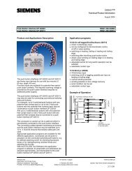
Potential residual hazard from contact with medium-voltage (230 VAC) conductors.<br />
When the <strong>SDK</strong>-<strong>U4</strong>-<strong>10</strong> (<strong>EIB</strong>) is used <strong>for</strong> its intended purpose, the equipment meets all relevant<br />
standards and regulations relating to the avoidance of personal injury and property damage.<br />
However, residual hazards arising from power-conductors cannot be completely eliminated.<br />
The key areas with a potential residual hazard are shown in the adjacent illustration.<br />
The <strong>SDK</strong>-<strong>U4</strong>-<strong>10</strong> (<strong>EIB</strong>) universal <strong>dimmer</strong> must be installed and used only in a perfect condition and in accordance with the<br />
operating manual. The unit must be disconnected from the power supply be<strong>for</strong>e any electrical terminals (power supply and<br />
<strong>dimmer</strong> output, etc.) are connected or disconnected. Work carried out on live terminals can result in severe injury from electric<br />
shocks.<br />
Output LD is not disconnected from the power supply when the <strong>dimmer</strong> is switched off. A separate automatic safety cut-out<br />
must be installed in the power feed.<br />
The universal <strong>dimmer</strong> <strong>SDK</strong>-<strong>U4</strong>-<strong>10</strong> (<strong>EIB</strong>) cannot be used <strong>for</strong> a high voltage trans<strong>for</strong>mer <strong>for</strong> neon signs.<br />
If the universal <strong>dimmer</strong> <strong>SDK</strong>-<strong>U4</strong>-<strong>10</strong> (<strong>EIB</strong>) is used with a trans<strong>for</strong>mer <strong>for</strong> low voltage incandescent lamps, there must be assured<br />
that the inrush current never exceeds 22 A (danger with short connections, cold spiral-wound filament, aso.)<br />
Connection and disconnection of the load or parts of the load is not permitted during operation.<br />
Attention!<br />
Into the power feed there must be a miniature circuit breaker or a fuse adapted to the load (maximum <strong>10</strong>A type B).<br />
Connecting other load through the terminals "N" and "L" (looping) is not allowed.<br />
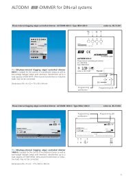
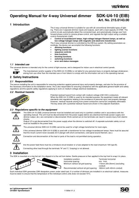
3 Installation<br />
The <strong>SDK</strong> is mounted on a top-hat rail. It is clipped in to the rail from below. Gentle pressure is then applied to the top front to snap it in place.<br />
DIM4FU-IP<br />
eibDUO<br />
Lingg &Janke<br />
4 x 570W /VA 230V 50/60Hz<br />
<strong>10</strong>A 4<br />
230 VAC 2.5 A<br />
A B C D<br />
N-N L-L LD N-N L-L LD N-N L-L LD N-N L-L LD<br />
Installation position:<br />
Terminals horizontal<br />
Horizontal spacing:<br />
min. 1mm<br />
Minimum vertical rail grid spacing: 115mm (90+25mm) (excluding<br />
conduit)<br />
Recommended vertical rail grid spacing: 160mm (with 40mm conduit)<br />
Each individual <strong>SDK</strong> generates 23W dissipation power under rated load. If a number of <strong>dimmer</strong>s are installed in an electrical cabinet, measures<br />
must be taken to ensure that the temperature of the individual control units does not exceed 70°C.<br />
se Lightmanagement AG<br />
CH-8957 Spreitenbach 11599e V1.2
<strong>SDK</strong>-<strong>U4</strong>-<strong>10</strong> (<strong>EIB</strong>) <strong>Operating</strong> <strong>Manual</strong> 2<br />
4 Control Modes<br />
The <strong>SDK</strong> is controlled by a <strong>EIB</strong> standard bus.<br />
The following illustrations show the connections used and the required settings.<br />
4.1 Connection of the <strong>EIB</strong> bus<br />
The <strong>EIB</strong> bus contains power supply (24V) as well as the bus signal (telegram)<br />
in a 2wire twisted pair cable.<br />
Connect the <strong>EIB</strong> bus to the two plug-in terminals marked "BUS". Connect<br />
the negative polarity to the black and the positive to the red plug-in terminal.<br />
<strong>SDK</strong>-<strong>U4</strong>-<strong>10</strong> (<strong>EIB</strong>)<br />
<strong>EIB</strong> -<br />
<strong>EIB</strong> +<br />
black<br />
red<br />
PE<br />
<strong>EIB</strong>-Bus<br />
4.2 <strong>Operating</strong> Parameters<br />
The system programmer can set the following parameters <strong>for</strong> each channel:<br />
• <strong>Operating</strong> mode (each channel separately or two parallel)<br />
• Switching functions<br />
• Time functions<br />
• Lighting scenes functions<br />
• Sequence control<br />
• Blocking functions<br />
• <strong>Operating</strong> and error status<br />
4.3 Commissioning<br />
When delivered, the <strong>SDK</strong>-<strong>U4</strong>-<strong>10</strong> (<strong>EIB</strong>) has no device and group addresses.<br />
The needed functions can be activated in the parameter setting. During project management with the ETS software only the activated objects<br />
will be visible.<br />
Important:<br />
Due to the built in bus coupler (BCU 2.1) the following measures must be taken be<strong>for</strong>e commissioning the device:<br />
<strong>for</strong> ETS 2.0 V1.2 / 1.3 and <strong>for</strong> ETS 3.0<br />
- service packs and all patches must be installed<br />
- product data base must not be older than 09/2005<br />
The application program must al<strong>way</strong>s be completely copied into the device. Partial copies lead to malfunctioning.<br />
For announcing the device to the system, press the "PROG"-button with a small screwdriver. The red LED will light up during the transmission.<br />
11599e V1.2<br />
se Lightmanagement AG<br />
CH-8957 Spreitenbach
3 <strong>SDK</strong>-<strong>U4</strong>-<strong>10</strong> (<strong>EIB</strong>) <strong>Operating</strong> <strong>Manual</strong><br />
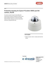
5 Load Circuit<br />
The 4-<strong>way</strong> universal <strong>dimmer</strong> is capable of<br />
controlling 230V incandescent lamps, low<br />
voltage halogen lamps with electronic or<br />
magnetic trans<strong>for</strong>mers up to a maximum<br />
current of 2.5 A (570 W). The dimmed voltage<br />
is present at output "LD". The universal <strong>dimmer</strong><br />
uses transistor circuitry to control the<br />
output voltage.<br />
Mixed load (inductive and capacitive) on one<br />
output are not allowed!<br />
From one channel to the next channel on the<br />
same <strong>dimmer</strong> the connections "N" and "L" may<br />
be looped (two terminals per connection). It is<br />
not allowed to connect another device through<br />
these terminals.<br />
Test function:<br />
Each circuit can be individually tested by<br />
pressing the relevant "TEST"-key on the power<br />
section. One press of the key switches the<br />
circuit on. A second, long press activates<br />
dimming, while a third press reverses the<br />
dimming into brightening. To switch off, it is<br />
necessary to interrupt the power supply (safety<br />
cut-out). A value generated with the test-key is<br />
overwritten if another value is demanded from<br />
the <strong>EIB</strong> bus (and vice versa).<br />
INCANDESCENT LAMP<br />
LOW-VOLTAGE-HALOGEN<br />
LAMP<br />
5.1 Parallel power connection<br />
To increase the power, two dimming circuits ( A+B and C+D ) can be software-connected in parallel ( 2 x 570W = 1140W ).<br />
• The circuits connected together must be in the same phase.<br />
• On the power section, the contacts of the common dimming circuits must be connected together (L with L, N with N and LD with LD).<br />
• The parallel connection must be software-programmed.<br />
6 LED Indicators on the Dimmer<br />
The <strong>dimmer</strong> has 1 LED on the interface section and 4 LEDs on the power section:<br />
Interface section<br />
Power section<br />
Interface section:<br />
Red LED ON During pressing the programming button the LED is on.<br />
OFF Unit is operating normally or supply is not connected.<br />
Power section:<br />
Green LED 1–4 ON Dimming circuit on (over the <strong>EIB</strong> bus or the "Test" keys).<br />
OFF Dimming circuit off.<br />
7 Fault Finding and Elimination<br />
Fault<br />
Lamp does not brighten.<br />
Remedy<br />
The relevant lighting circuit can be dimmed or brightened by pressing one of the keys on the power section,<br />
after removing the bus cable. If the circuits do not respond, check the load circuit wiring.<br />
Check the bus voltage on the <strong>SDK</strong> (red LED must come on while pressing the programming button).<br />
se Lightmanagement AG<br />
CH-8957 Spreitenbach 11599e V1.2
<strong>SDK</strong>-<strong>U4</strong>-<strong>10</strong> (<strong>EIB</strong>) <strong>Operating</strong> <strong>Manual</strong> 4<br />
8 Technical Data<br />
Dimensions:<br />
Electrical data: per channel<br />
Mains voltage: 230 V ±<strong>10</strong>%<br />
Mains frequency:<br />
50 / 60 Hz<br />
Preliminary fuse: <strong>10</strong> A max. (type B)<br />
Dimming output technology: Transistor-driven <strong>for</strong>ward phase<br />
control / reverse phase control<br />
Maximum load, dimming<br />
output:<br />
570 W / VA (2.5A) resistive /<br />
inductive / capacitive<br />
Minimum load, dimming output: 5 W resistive<br />
Leakage power at rated load: 5.7 W at rated load<br />
Leakage power on standby: 1.4 W<br />
Cooling:<br />
Natural air circulation<br />
No-load voltage:<br />
Approx. 55 Vrms<br />
Short-circuit protection: Electronic fast cut-off<br />
Overload protection:<br />
Temperature monitoring. (trigger<br />
value approx. 85°C)<br />
Symmetry errors:<br />
Not measurable<br />
Impulse switching flank: <strong>10</strong>0µs, rated load with inc.-lamp<br />
Operational and fault indicator: Green "Run" LED per channel<br />
Keys (integrated single-key<br />
control):<br />
On / brighter / <strong>dimmer</strong>. (<strong>for</strong> test<br />
purposes at initial start-up)<br />
Insulation:<br />
2500 V betw. interface / <strong>dimmer</strong><br />
Switch-on delay:<br />
approx. 1s (mains switch-on)<br />
Type<br />
Article number<br />
Mechanical data:<br />
Case:<br />
<strong>SDK</strong>-<strong>U4</strong>-<strong>10</strong> (<strong>EIB</strong>)<br />
215.0143.00<br />
Steel sheet with aluminium cooler<br />
Dimensions: Width: 216.5 mm<br />
Height: 90 mm<br />
Depth: 44 mm (from top-hat pr.)<br />
Weight:<br />
850 g<br />
Installation:<br />
On DIN top-hat profile rails 35 mm<br />
Mains power connection: 4 plug-in terminals max. 2.5 mm²<br />
Load connection:<br />
1 plug-in terminal max. 2.5 mm²<br />
Control connections:<br />
2 plug-in terminals max. 0.8 mm²<br />
Ambient conditions:<br />
Ambient temperature:<br />
ta 0-40 °C max. Do not block<br />
airflow at cooler.<br />
Storage temperature:<br />
70 °C max.<br />
Air humidity:<br />
<strong>10</strong>%...80% relative air humidity,<br />
non-condensing<br />
Case temperature:<br />
tc 70 °C max.<br />
IP protection:<br />
IP20<br />
Control:<br />
Operational voltage:<br />
Bus protocol:<br />
Indications:<br />
Control elements:<br />
CE mark:<br />
EN 60669-2-1<br />
EN 55015<br />
EN 55014-2 (VDE 0875)<br />
EN 6<strong>10</strong>00-3-2<br />
28VDV (from <strong>EIB</strong>-Bus)<br />
<strong>EIB</strong><br />
LED (Program) red<br />
Programming button<br />
as per 89/336/EWG and<br />
73/23/EWG<br />
Safety requirements<br />
Interference transmission<br />
Radio interference<br />
Harmonics<br />
The product data base <strong>for</strong> the <strong>SDK</strong>-<strong>U4</strong>-<strong>10</strong> (<strong>EIB</strong>) can be found in the<br />
"download"-section on www.se-ag.ch.<br />
Would you like more «varintens» in<strong>for</strong>mation? Visit our web site!<br />
www.se-ag.ch<br />
e-mail: info@se-ag.ch<br />
se Lightmanagement AG<br />
Güterstrasse 11, CH-8957 Spreitenbach,<br />
Switzerland<br />
Tel. +41 56 418 76 11, Fax +41 56 401 49 86<br />
11599e V1.2<br />
se Lightmanagement AG<br />
CH-8957 Spreitenbach