Siemens RS232 Interface N 148/02 Data Sheet - siemens knx ...
Siemens RS232 Interface N 148/02 Data Sheet - siemens knx ...
Siemens RS232 Interface N 148/02 Data Sheet - siemens knx ...

Create successful ePaper yourself
Turn your PDF publications into a flip-book with our unique Google optimized e-Paper software.
instabus EIB<br />
Technical Product Information<br />
October 2001<br />
<strong>Interface</strong> N <strong>148</strong><br />
RS 232<br />
5WG1 <strong>148</strong>-1AB<strong>02</strong><br />
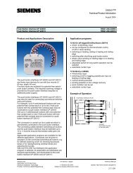
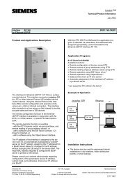
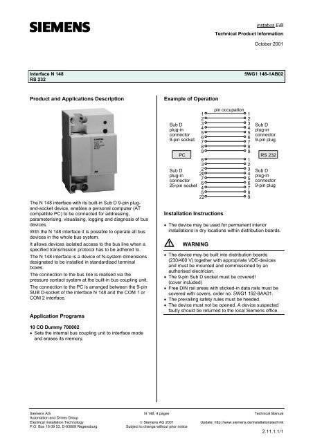
Product and Applications Description<br />
Example of Operation<br />
The N <strong>148</strong> interface with its built-in Sub D 9-pin plugand-socket<br />
device, enables a personal computer (AT<br />
compatible PC) to be connected for addressing,<br />
parameterising, visualising, logging and diagnosis of bus<br />
devices.<br />
With the N <strong>148</strong> interface it is possible to operate all bus<br />
devices in the whole bus system.<br />
It allows devices isolated access to the bus line when a<br />
specified transmission protocol has to be adhered to.<br />
The N <strong>148</strong> interface is a device of N-system dimensions<br />
designated to be installed in standardised terminal<br />
boxes.<br />
The connection to the bus line is realised via the<br />
pressure contact system at the built-in bus coupling unit.<br />
The connection to the PC is arranged between the 9-pin<br />
SUB D-socket of the interface N <strong>148</strong> and the COM 1 or<br />
COM 2 interface.<br />
Application Programs<br />
Sub D<br />
plug-in<br />
connector<br />
9-pin socket<br />
PC<br />
Sub D<br />
plug-in<br />
connector<br />
25-pin socket<br />
1<br />
2<br />
3<br />
4<br />
5<br />
6<br />
7<br />
8<br />
9<br />
8<br />
3<br />
2<br />
20<br />
7<br />
6<br />
4<br />
5<br />
22<br />
Installation Instructions<br />
pin occupation<br />
1<br />
2<br />
3<br />
4<br />
5<br />
6<br />
7<br />
8<br />
9<br />
1<br />
2<br />
3<br />
4<br />
5<br />
6<br />
7<br />
8<br />
9<br />
Sub D<br />
plug-in<br />
connector<br />
9-pin plug<br />
RS 232<br />
Sub D<br />
plug-in<br />
connector<br />
9-pin plug<br />
• The device may be used for permanent interior<br />
installations in dry locations within distribution boards.<br />
V<br />
WARNING<br />
• The device may be built into distribution boards<br />
(230/400 V) together with appropriate VDE-devices<br />
and must be mounted and commissioned by an<br />
authorised electrician.<br />
• The 9-pin Sub D socket must be covered!<br />
(cover included)<br />
• Free DIN rail areas with sticked-in data rails must be<br />
covered with covers, order no. 5WG1 192-8AA01.<br />
• The prevailing safety rules must be heeded.<br />
• The device must not be opened. A device suspected<br />
faulty should be returned to the local <strong>Siemens</strong> office.<br />
10 CO Dummy 7000<strong>02</strong><br />
• Sets the internal bus coupling unit to interface mode<br />
and erases its memory.<br />
<strong>Siemens</strong> AG N <strong>148</strong>, 4 pages Technical Manual<br />
Automation and Drives Group<br />
Electrical Installation Technology © <strong>Siemens</strong> AG 2001 Update: http://www.<strong>siemens</strong>.de/installationstechnik<br />
P.O. Box 10 09 53, D-93009 Regensburg<br />
Subject to change without prior notice<br />
2.11.1.1/1
instabus EIB<br />
Technical Product Information<br />
October 2001<br />
<strong>Interface</strong> N <strong>148</strong><br />
RS 232<br />
5WG1 <strong>148</strong>-1AB<strong>02</strong><br />
Technical Specifications<br />
Power supply<br />
via bus cable<br />
Transmission rate<br />
9600 bit/s<br />
Control elements<br />
1 learning button:<br />
for switching between normal operating mode and<br />
addressing mode<br />
Display elements<br />
1 red LED:<br />
for monitoring bus voltage and displaying mode,<br />
selected with the learning button<br />
Connections<br />
• bus line, pressure contacts on data rail<br />
• RS 232 interface: 9-pin SUB-D socket<br />
length of data cable: max. 15 m<br />
• connection cable available from authorised electronics<br />
stores (see example of operation)<br />
Physical specifications<br />
• housing: plastic<br />
• N-system DIN-rail mounted device,<br />
width: 3 SUs (1SU = 18mm)<br />
• weight: approx. 180 g<br />
• fire load: approx. 3000 kJ ± 10 %<br />
• installation: rapid mounting on<br />
DIN EN 50<strong>02</strong>2-35 x 7,5 rail<br />
Electrical safety<br />
• fouling class (according to IEC 664-1): 2<br />
• protection (according to EN 60529): IP 20<br />
• protection class (according to IEC 1140): III<br />
• overvoltage class (according to IEC 664-1): III<br />
• bus: safety extra low voltage SELV DC 24 V<br />
• the device complies with<br />
EN 50 090-2-2 and IEC 664-1: 1992<br />
Reliability<br />
rate of failure: 736 fit at 40 °C<br />
Electromagnetic compatibility<br />
complies with<br />
EN 50081-1, EN 50082-2 and EN 50 090-2-2<br />
Environmental specifications<br />
• climatic conditions: EN 50090-2-2<br />
• ambient temperature operating: - 5 ... + 45 °C<br />
• ambient temperature non-op.: - 25 ... + 70 ° C<br />
• relative humidity (non-condensing): 5 % to 93 %<br />
Certification<br />
EIB certificate<br />
CE norm<br />
complies with the EMC regulations (residential and<br />
functional buildings), and low voltage regulations<br />
Location and Function of the Display and<br />
Operator Elements<br />
A1<br />
A2<br />
A3<br />
A4<br />
A5<br />
A1<br />
Figure 1: Location of the display and operator elements<br />
A1 Clamp for connection cable (max. ∅ 8 mm)<br />
A2 LED for indicating normal operating mode (LED off)<br />
and addressing mode (LED on); upon receiving the<br />
physical address the device automatically returns to<br />
normal operating mode<br />
A3 Learning button for switching between normal<br />
operating mode and addressing mode for receiving<br />
the physical address<br />
A4 9-pin Sub D socket<br />
A5 Label for noting the physical address<br />
Mounting and Wiring<br />
General description<br />
The N-system DIN-rail device (3 SUs) can be installed to<br />
N-system distribution boards, surface or flush mounted,<br />
or to any DIN-rail EN 50<strong>02</strong>2-35 x 7,5 available that has a<br />
data installed.<br />
The connection to the bus line is established by clicking<br />
the device onto the DIN-rail (with a data rail installed).<br />
Take care that the type plates of all devices on a DIN-rail<br />
can be read in the same direction, guaranteeing the<br />
devices are polarised correctly.<br />
Technical Manual N <strong>148</strong>, 4 pages <strong>Siemens</strong> AG<br />
Automation and Drives Group<br />
Update: http://www.<strong>siemens</strong>.de/installationstechnik © <strong>Siemens</strong> AG 2001 Electrical Installation Technology<br />
Subject to change without prior notice<br />
P.O. Box 10 09 53, D-93009 Regensburg<br />
2.11.1.1/2
instabus EIB<br />
Technical Product Information<br />
October 2001<br />
<strong>Interface</strong> N <strong>148</strong><br />
RS 232<br />
5WG1 <strong>148</strong>-1AB<strong>02</strong><br />
Mounting DIN-rail devices (Figure 2)<br />
- Slide the device (B1) onto the DIN-rail (B2) and<br />
- swivel back the device (B1) until the slide clicks into<br />
place audibly.<br />
Dismounting DIN-rail devices (Figure 2)<br />
- Remove the cover.<br />
- Remove the clamps for connection cables.<br />
- Unplug the 9-pin Sub D connector.<br />
- Press down the slide (C3) with a screw-driver, click it<br />
into place by a slight pressure and<br />
- swivel the device (C1) from the DIN-rail (C2).<br />
Dimension Diagram<br />
Dimensions in mm<br />
90<br />
45<br />
B2<br />
C2<br />
b<br />
44<br />
55<br />
B1<br />
C1<br />
C3<br />
b = 3 TE<br />
1 Spacer unit (1 SU) = 18 mm<br />
Figure 2: Mounting and dismounting a DIN-rail device<br />
<strong>Siemens</strong> AG N <strong>148</strong>, 4 pages Technical Manual<br />
Automation and Drives Group<br />
Electrical Installation Technology © <strong>Siemens</strong> AG 2001 Update: http://www.<strong>siemens</strong>.de/installationstechnik<br />
P.O. Box 10 09 53, D-93009 Regensburg<br />
Subject to change without prior notice<br />
2.11.1.1/3
instabus EIB<br />
Technical Product Information<br />
October 2001<br />
<strong>Interface</strong> N <strong>148</strong><br />
RS 232<br />
5WG1 <strong>148</strong>-1AB<strong>02</strong><br />
Notes<br />
Technical Manual N <strong>148</strong>, 4 pages <strong>Siemens</strong> AG<br />
Automation and Drives Group<br />
Update: http://www.<strong>siemens</strong>.de/installationstechnik © <strong>Siemens</strong> AG 2001 Electrical Installation Technology<br />
Subject to change without prior notice<br />
P.O. Box 10 09 53, D-93009 Regensburg<br />
2.11.1.1/4