fastcom®: 422/4-isa hardware manual - Commtech-fastcom.com
fastcom®: 422/4-isa hardware manual - Commtech-fastcom.com
fastcom®: 422/4-isa hardware manual - Commtech-fastcom.com

You also want an ePaper? Increase the reach of your titles
YUMPU automatically turns print PDFs into web optimized ePapers that Google loves.
9011 E. 37TH STREET N.<br />
WICHITA, KANSAS 67226-2006<br />
(316) 636-1131<br />
FAX (316) 636-1163<br />
http://www.<strong>com</strong>mtech-<strong>fast<strong>com</strong></strong>.<strong>com</strong>/<br />
COPYRIGHT (C) 1999, 2002, 2003, 2005, 2010<br />
All rights reserved, including those to reproduce this document or parts thereof in<br />
any form without permission in writing from <strong>Commtech</strong>, Inc.<br />
FASTCOM and the “Alpha Lemur” are registered trademarks of <strong>Commtech</strong>, Inc.<br />
IBM is a registered trademark of International Business Machines Corporation.<br />
Microsoft is a registered trademark of Microsoft Corporation.<br />
WINDOWS is a trademark of Microsoft Corporation.
REVISION NOTES<br />
REVISION PAGE NUMBER CHANGES MADE<br />
2.1 23 Changed warranty to 2 years<br />
2.2 23 Updated contact information<br />
2.3 23 Changed warranty period to lifetime<br />
2.4 18 CTS+/- pin numbers swapped<br />
2.5 23 Changed warranty to limited lifetime<br />
2.6 23 Updated Limitation of Liability
CONTENTS<br />
"CE" CERTIFICATE ................................................................................................................ 1<br />
INTRODUCTION<br />
Description / Block Diagram.............................................................................................. 3<br />
Specifications / Features................................................................................................... 4<br />
Board Layout..................................................................................................................... 5<br />
INSTALLATION<br />
Selecting An Operating Mode ........................................................................................... 6<br />
Factory Switch Settings..................................................................................................... 6<br />
Installing the Board ........................................................................................................... 7<br />
Testing the Installation ...................................................................................................... 7<br />
SWITCH DESCRIPTIONS<br />
Windows Mode................................................................................................................ 10<br />
Fast<strong>com</strong> Mode ................................................................................................................ 10<br />
Switch 1, Address...................................................................................................... 11<br />
Switches 2 & 3, IRQ .................................................................................................. 12<br />
Interrupt Sharing........................................................................................................ 13<br />
Switch 4, Operating Mode ......................................................................................... 14<br />
OPERATING MODES<br />
RS-<strong>422</strong> / RS-485............................................................................................................. 15<br />
Termination Resistance .................................................................................................. 16<br />
Termination Resistors ..................................................................................................... 17<br />
CABLE<br />
DB37 to DB9 Adapter Cable ........................................................................................... 18<br />
DB9 Pin Description ........................................................................................................ 18<br />
RS-<strong>422</strong> ............................................................................................................................ 19<br />
RS-485 ............................................................................................................................ 19<br />
PROGRAMMING<br />
I-STAT Register .............................................................................................................. 21<br />
IMPORTANT NOTES............................................................................................................ 22<br />
TECHNICAL SUPPORT ....................................................................................................... 23<br />
APPENDIX A<br />
I/O Address Settings ....................................................................................................... 24<br />
APPENDIX B<br />
16C854 UART Technical Data........................................................................................ 29
1<br />
EUROPEAN UNION DECLARATION OF CONFORMITY<br />
Information Technology Equipment<br />
The Company COMMTECH, INC. declares under its own and full responsibility that the product<br />
" Fast<strong>com</strong>: <strong>422</strong>/4-ISA - Revision 1.0 "<br />
on which is attached this Certificate is <strong>com</strong>pliant to the "89/336/EEC" Directive, amended by 92/31/EEC and<br />
93/88/EEC.<br />
[ ] The product identified above <strong>com</strong>plies with the requirements of the above EU Directive by meeting the<br />
following standards:<br />
• EN 50081-1 (1992) EMC Generic Emission Standard - Part 1, Residential, Commercial and Light Industry<br />
- EN 55022 (1995), CISPR 22 (1993) Limits and Methods of Measurement of Radio Disturbance<br />
Characteristics of Information Technology Equipment, 30 MHz - 1 GHz, Class B Limits<br />
• EN 50082-1 (1992) EMC Generic Immunity Standard - Part 1, Residential, Commercial and Light Industry<br />
- IEC 801-2 (1984), Method of Evaluating Susceptibility to Electrostatic Discharge, Level 4<br />
- IEC 801-3 (1984), Radiated Electromagnetic field Requirements, Level 3<br />
- IEC 801-4 (1988), Electrical Fast Transient/Burst Requirements, Level 2<br />
Products listed on this declaration are exempt from the requirements of the 73/23/EEC directive due to the input<br />
voltage specification as stated in Article 1 of the directive.<br />
The technical documentation required to demonstrate that this product meets the requirements of the EMC Directive<br />
has been <strong>com</strong>piled by the signatory below and is available for inspection by the relevant enforcement authorities.<br />
In WICHITA, KS on December 23 rd of 1995<br />
9011 E. 37th Street North<br />
Wichita, KS 67226-2006<br />
(316) 636-1131<br />
Fax (316) 636-1163<br />
Mr. Glen R. Alvis<br />
Chief Engineer
3<br />
INTRODUCTION<br />
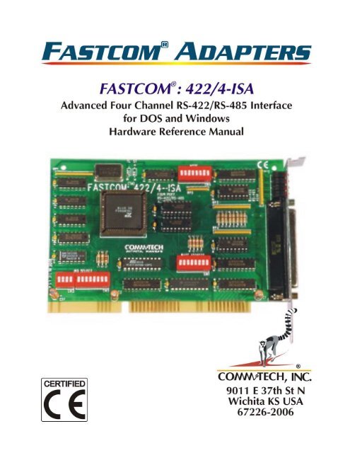
The new FASTCOM: <strong>422</strong>/4-ISA adapter is the fastest (1.5 Mbps), most advanced, four-port<br />
RS-<strong>422</strong> asynchronous adapter in the industry. Primarily designed for <strong>com</strong>mercial, industrial,<br />
and OEM applications, the FASTCOM: <strong>422</strong>/4-ISA features four discrete RS-<strong>422</strong> channels,<br />
<strong>com</strong>plete with RTS and CTS flow control signals.<br />
The advanced UART on the FASTCOM: <strong>422</strong>/4-ISA features full <strong>com</strong>patibility with standard<br />
16C550 and 16C650 UARTs, but provides extraordinary 128- byte receive and transmit<br />
FIFOs for buffering. This buffering is extremely important when working with RS-<strong>422</strong>/RS-485<br />
<strong>com</strong>munications within high overhead operating systems such as Windows NT and Windows<br />
95/98. The extra-deep FIFOs prevent data loss due to overrun and dramatically improve data<br />
throughput in all applications. The advanced UART on the FASTCOM: <strong>422</strong>/4-ISA is capable<br />
of all standard baud rates plus a high-speed mode capable of up to an amazing 1.5<br />
Mbps (crystal change required).<br />
The Fast<strong>com</strong> CD contains software drivers for DOS. The FASTCOM: <strong>422</strong>/4-ISA is designed<br />
with a <strong>com</strong>patible mode for operation in the Windows environment. The "shared interrupt"<br />
design and user selectable address allow the installation of multiple FASTCOM: <strong>422</strong>/4-ISA<br />
cards in the same system.<br />
The FASTCOM: <strong>422</strong> family of adapters includes the dual channel FASTCOM: <strong>422</strong>/2-ISA, the<br />
dual channel FASTCOM: <strong>422</strong>/2-104 for the PC/104 bus, and the fully isolated FASTCOM:<br />
IG<strong>422</strong>/1-ISA. PCI bus versions are also available.<br />
The following is the basic structure of the FASTCOM: <strong>422</strong>/4-ISA:
4<br />
SPECIFICATIONS:<br />
UART:<br />
16C854<br />
PROTOCOL:<br />
Asynchronous<br />
BAUD RANGE: Up to 1.5 Mbaud *<br />
BUS:<br />
16 bit ISA<br />
BUFFERING:<br />
Transmit - 128 bytes<br />
Receive - 128 bytes<br />
POWER<br />
REQUIREMENTS:<br />
+5 @ 400mA (Typical)<br />
INTERFACE:<br />
RS-<strong>422</strong>/RS-485C<br />
DB9 connector<br />
FEATURES:<br />
FASTCOM: <strong>422</strong>/4-ISA<br />
CE certified<br />
Four independent RS-<strong>422</strong>/RS-485 channels<br />
Transmit/Receive status LEDs for each channel<br />
TX, RX, RTS, CTS signals for each channel<br />
Excellent line noise immunity<br />
Fully <strong>com</strong>patible with our older models:<br />
Fast<strong>com</strong>: <strong>422</strong>/4W, Fast<strong>com</strong>: <strong>422</strong>/4W-ST<br />
Two Address Modes<br />
WINDOWS MODE: Ports are configured as COM1, COM2, COM3, and COM4<br />
FASTCOM MODE: Ports are assigned address and IRQ by the user<br />
RS-485<br />
Up to 32 stations on same “twisted-pair” network<br />
RTS control of the line driver<br />
New high performance 16C854 UART<br />
Standard on the FASTCOM: <strong>422</strong>/4-ISA, no extra charge<br />
High throughput, full <strong>com</strong>patibility, higher speed<br />
Cable, Documentation, Software Drivers included<br />
Made in Wichita, Kansas, USA<br />
* A clock change is required to achieve baud rates higher than 115.2 Kbaud.
5<br />
FASTCOM: <strong>422</strong>/4-ISA<br />
BOARD LAYOUT<br />
TRANSMIT<br />
RECEIVE<br />
STATUS<br />
LEDs<br />
16C854 UART<br />
DB37<br />
CONNECTO<br />
INTERRUPT SELECT<br />
SWITCHES<br />
BASE ADDRESS<br />
SWITCH<br />
PACKING LIST<br />
FASTCOM: <strong>422</strong>/4-ISA CARD<br />
CABLE ASSEMBLY<br />
FASTCOM CD<br />
If an omission has been made, please call technical support for a replacement.
6<br />
INSTALLATION<br />
SELECTING AN OPERATING MODE<br />
Important: Observe Electrostatic Discharge (ESD) precautions when handling the<br />
FASTCOM: <strong>422</strong>/4-ISA board.<br />
The FASTCOM: <strong>422</strong>/4-ISA has two modes of operation: the FASTCOM MODE and the<br />
WINDOWS MODE. Decide which mode you want to use before you install the FASTCOM:<br />
<strong>422</strong>/4-ISA in your <strong>com</strong>puter.<br />
In the FASTCOM MODE (factory default setting), the FASTCOM: <strong>422</strong>/4-ISA is<br />
<strong>hardware</strong>/software <strong>com</strong>patible with our original FASTCOM: <strong>422</strong>/4 adapter. The address/IRQ<br />
for each channel is determined by setting Switch 1 (Address) and Switches 2 and 3 (IRQ<br />
Level). The FASTCOM MODE is typically used for systems that require multiple serial ports<br />
and already have COM1 and/or COM2 installed. This mode would most likely be used by<br />
OEMs and system designers who are writing their own software. The FASTCOM MODE also<br />
allows you to install multiple FASTCOM: <strong>422</strong>/4-ISA adapters in your <strong>com</strong>puter.<br />
In the WINDOWS MODE, each channel of the FASTCOM: <strong>422</strong>/4-ISA is assigned an<br />
address/IRQ level that provides true COM1, COM2, COM3, and COM4 ports and full<br />
<strong>com</strong>patibility with off-the-shelf DOS/WINDOWS software packages.<br />
The operating mode is selected by the setting of Switch 2, Position 6. In the ON position, the<br />
WINDOWS MODE is selected; in the OFF position, the FASTCOM MODE is selected.<br />
The FASTCOM: <strong>422</strong>/4-ISA is shipped from the factory in the FASTCOM MODE. The following<br />
are the factory switch settings:<br />
FACTORY SWITCH SETTINGS<br />
ADDRESS (SW1) = 280H<br />
ON<br />
1 2 3 4 5 6 7 8<br />
IRQ SELECT (SW3 & SW2) = 5<br />
ON<br />
ON<br />
MODE (SW4)<br />
CTS HANDSHAKING DISABLED<br />
RS-485 DRIVER CONTROL DISABLED<br />
ON<br />
1 2 3 4 5 6 7 8<br />
1 2 3 4<br />
1 2 3 4 5 6 7 8
7<br />
INSTALLING THE FASTCOM: <strong>422</strong>/4-ISA IN THE PC<br />
1. Unpack the FASTCOM: <strong>422</strong>/4-ISA. Keep the box and static bag for warranty repair<br />
returns.<br />
2. Check the switches to be sure that they are set for the mode you want.<br />
3. Select an open slot in your PC (16 bit slot).<br />
4. After removing the blank bracket from your PC, install the FASTCOM: <strong>422</strong>/4-ISA in the<br />
PC by pressing it firmly into the slot. Install the bracket screw to hold it firmly in place.<br />
5. Re-install the cover on your PC.<br />
TESTING THE INSTALLATION<br />
To fully test the installation of your FASTCOM: <strong>422</strong>/4-ISA, you will need to build a “loop back<br />
plug”. Materials needed are a DB9 male plug, solder cup style, and a few short pieces of 20 or<br />
24 AWG stranded wire. Jumper the pins together on the DB9 as illustrated below:<br />
4 TX+<br />
5 TX-<br />
8 RX+<br />
9 RX-<br />
4<br />
5<br />
8<br />
9<br />
TESTING YOUR FASTCOM ASYNC ISA PORT IN DOS<br />
1. Be sure that the board is in the RS-<strong>422</strong>, no handshaking mode.<br />
2. Plug the loop back test plug into the Channel 1 cable of the FASTCOM: <strong>422</strong>/4-ISA.<br />
3. Turn the <strong>com</strong>puter on, get to a DOS prompt.<br />
4. If you have not done so already, you will need to configure and install SMART14 software<br />
drivers. Place the SMART14 diskette in drive A or B. Create a directory on your hard disk<br />
named SMART14. Copy all of the files from the SMART14 directory of the diskette to your<br />
hard disk. Run the INSTALL program and supply the information that it requests. After you<br />
have configured SMART14, load it by typing SMART14 at the DOS prompt.<br />
5. Run the TERM test program described in the SMART14 <strong>manual</strong>.
8<br />
TESTING YOUR FASTCOM ASYNC ISA PORT IN WINDOWS<br />
These instructions assume that you have already installed the card and have followed the<br />
installation instructions. In NT, the ports should be visible in the Control Panel->Ports applet.<br />
In Windows 95/98, the ports should show up in Control Panel in the System icon’s Device<br />
Manager. The port installation instructions can be found on the disk in:<br />
For Windows95/98 D:\Fast<strong>com</strong>_Disks\Smart14\Windows\W95\howto.txt<br />
For Windows NT D:\Fast<strong>com</strong>_Disks\Smart14\Windows\NT\howto.txt<br />
1. Install the loopback plug on the port to test.<br />
2. Find and run the TTY.EXE program.<br />
From the Start menu, choose Run, browse to and select<br />
D:\Fast<strong>com</strong>_Disks\Smart14\windows\win32\tty\tty.exe.<br />
Select TTY.EXE and click open.<br />
Click OK to run the TTY program.<br />
3. From the menu bar on the TTY program, select Settings.<br />
Select the port to test (e.g., COM5)<br />
Uncheck all of the flow checkboxes (DTR/DSR, RTS/CTS, XON/XOFF).<br />
Click OK.<br />
4. From the TTY main menu bar select Action, then Connect.<br />
5. At this point you should see a blinking cursor in the upper left corner of the TTY window.<br />
Try to type on the keyboard; you should see the characters that you are typing in the TTY<br />
window. If you see what you type, the port is passing the loopback, and is installed and<br />
functioning correctly.<br />
If you get a "Connection Failed" message box when you try the Action ->Connect sequence,<br />
some possible causes are:<br />
1. Incorrect or mismatched address or IRQ settings between what the switches on the<br />
board are set to and what is set up in the driver. You can check the driver settings in<br />
NT using Control Panel ->Ports ->COMx ->Advanced. In Windows 95/98, you need<br />
to look in Control Panel ->System, Device Manager tab, Ports (COM & LPT), select<br />
the COM#, click the Properties button, then the Resources tab. Check the address<br />
switch settings using the table in the back of the <strong>manual</strong>. Realize that multiport<br />
cards addresses are sequential (if set to base address of 0x280, then the addresses<br />
for the four ports will be 0x280, 0x288, 0x290, and 0x298).<br />
If you are using NT, you can run NT Diagnostics (from the Start button, choose<br />
Programs ->Administrative Tools ->Windows NT Diagnostics) to verify that there is<br />
not another device trying to use the address range or IRQ. The Resources tab in<br />
Windows 95 (location listed above) should indicate a resource conflict if another<br />
device is using the same I/O range or IRQ. Even if you donÆt see a listed conflict,<br />
try a different address/IRQ <strong>com</strong>bination if all of the settings are matched and it still<br />
doesnÆt work.
9<br />
If you have tried a couple of different address/IRQ <strong>com</strong>binations without success,<br />
you might try using an Ohm meter or continuity tester to verify that the switch<br />
positions are actually what they are set to. The switch positions that are ON should<br />
be closed (about 0 ohms); the ones that are OFF should be open (not 0 Ohms).<br />
Sometimes the dip switches will get stuck in either the on or off position irrespective<br />
of the position of the slide. If this happens, try toggling the stuck position on and off<br />
a few times and re-check it.<br />
2. In NT, if multiple ports are opened (running more than one instance of TTY), the<br />
ports are using the same IRQ, and the PermitShare registry entry is 0, the second<br />
port to be opened will fail. Use the registry editor and expand<br />
HKEY_LOCAL_MACHINE ->SYSTEM ->CurrentControlSet ->Services ->Serial,<br />
change the PermitShare value from 0 to 1, reboot, and run the test again.<br />
If you get to the blinking cursor stage, but do not see what you type with the loopback plug<br />
installed, some possible reasons are:<br />
1. Incorrect/faulty loopback plug construction or a bad connection.<br />
2. If you have a RS-<strong>422</strong>/485 board, check to make sure that the 485 mode is d<strong>isa</strong>bled.<br />
The loopback test should be run in RS-<strong>422</strong> mode (the RS-485 driver control<br />
switches should be in the OFF position).<br />
3. The RTS/CTS flow control is checked and there is not a RTS->CTS loopback, or the<br />
CTS d<strong>isa</strong>bled switch is OFF. If you enable flow control, you must allow CTS to be<br />
active in order for the driver to transmit data. Either d<strong>isa</strong>ble flow control, or wire the<br />
RTS->CTS (and possibly DTR->DSR) loop and try the test again.<br />
4. Check to make sure that the loopback plug is on the correct port/cable (or that the<br />
correct port is selected in the settings dialog).<br />
5. If you type a character and the cursor stops blinking for a long time and the PC/TTY<br />
window stops responding (appears locked up) but returns to a blinking cursor state<br />
after a few minutes, this is a good indication that the interrupt setting on the card is<br />
not the same as the interrupt setting of the port in Windows. Re-verify that the IRQ<br />
setting on the board switches and in Control Panel are the same.
10<br />
FASTCOM: <strong>422</strong>/4-ISA OPERATING MODES<br />
The FASTCOM: <strong>422</strong>/4-ISA has two modes of operation: the FASTCOM MODE and the<br />
WINDOWS MODE. The operating mode is selected by the setting of Switch 2, Position 6. In<br />
the ON position, the WINDOWS MODE is selected. In the OFF position, the FASTCOM<br />
MODE is selected. In the FASTCOM MODE, the board address/IRQ configuration is<br />
determined by setting Switches 1, 2, and 3. In the WINDOWS MODE, each channel is<br />
assigned an address/IRQ level that provides “drop-in” <strong>com</strong>patibility with WINDOWS/DOS<br />
applications.<br />
WINDOWS MODE<br />
If the WINDOWS MODE is selected, the base address switch (Switch 1) is overridden. Switch<br />
2, Position 6 should be set to ON, and all other positions should be set to OFF. The<br />
Address/IRQ for each channel is as follows in WINDOWS MODE:<br />
CHANNEL ADDRESS IRQ NAME<br />
CHANNEL 1 3F8H 4 COM1:<br />
CHANNEL 2 2F8H 3 COM2:<br />
CHANNEL 3 3E8H 4 COM3:<br />
CHANNEL 4 2E8H 3 COM4:<br />
IMPORTANT: Be sure that Switch 2, Position 6 is ON and all other positions on Switch 2 are<br />
OFF.<br />
FASTCOM MODE SWITCH DESCRIPTIONS<br />
There are four dip switches on the FASTCOM: <strong>422</strong>/4-ISA, labeled SW1 through SW4 (See<br />
Board Layout Illustration for location). Switch 1 (labeled Base Address) is used to set the I/O<br />
address of the FASTCOM: <strong>422</strong>/4-ISA board. Switch 2 (labeled IRQ) serves three functions: it<br />
selects the IRQ level for the board, is used to enable/d<strong>isa</strong>ble interrupt sharing, and selects the<br />
operating mode for the board. Switch 3 is used to select upper level IRQ settings. Switch 4<br />
selects either RS-<strong>422</strong> or RS-485 mode and enables/d<strong>isa</strong>bles handshaking for each channel.
11<br />
SWITCH 1, ADDRESS<br />
Switch 1 decodes the PC address lines as follows:<br />
ON<br />
1 2 3 4 5 6 7 8 Address Line Hex value<br />
A12 1000<br />
A11<br />
A10<br />
A9<br />
A8<br />
A7<br />
A6<br />
A5<br />
800<br />
400<br />
200<br />
100<br />
80<br />
40<br />
20<br />
Address lines A5 through A12 are decoded by the<br />
setting of SW1 and set the base address of the<br />
FASTCOM: <strong>422</strong>/4-ISA. Address lines A3 and A4 are<br />
used on the board to select which port (1, 2, 3, or 4)<br />
you want to use. Address lines A0, A1, and A2 are<br />
used to select the registers within the UARTS.<br />
The above diagram illustrates a base address of 280<br />
Hex. Note that when a switch is ON it represents a “0”<br />
in the corresponding bit position (not a “1” as you might<br />
expect). Also, a switch that is OFF represents a “1” in<br />
the corresponding bit position. (If you would like to know why this is reversed, read a technical<br />
data sheet for the address decoder chip, a 74LS682).<br />
So, the SW1 diagram can be decoded as follows:<br />
A12 A11 A10 A9 A8 A7 A6 A5<br />
0 0 0 1 0 1 0 0<br />
You can determine the I/O address of the board by adding together the Hex values for each<br />
address line that is set to a “1”. In the illustration, only address lines A7 and A9 are set to “1”.<br />
So, add the Hex value of A9 (200H) and A7 (80H), and the result is the I/O base address<br />
(200H + 80H = 280H).<br />
Switch 1 is referred to as the Base Address switch because it marks the beginning address of<br />
the first channel on the FASTCOM: <strong>422</strong>/4-ISA board. The other channels are addressed as an<br />
offset to the first channel. For example, if we set the Base Address to 280H, note the address<br />
of each channel:<br />
CHANNEL BASE OFFSET ADDRESS<br />
1 280H + 0H = 280H<br />
2 280H + 8H = 288H<br />
3 280H + 10H = 290H<br />
4 280H + 18H = 298H<br />
We have provided a <strong>com</strong>prehensive guide to setting the address switch in<br />
Appendix A.<br />
Please note that not all of the I/O address space in a PC is available for your use. We have<br />
selected 280H as a default because it does not conflict with devices normally installed in a PC.<br />
However, if you wish to select another address, refer to Appendix A, I/O Address Usage Table,<br />
and select an address that does not conflict with devices installed in your PC. Keep in mind<br />
that the FASTCOM: <strong>422</strong>/4-ISA requires 32 Hex contiguous bytes of address space.
12<br />
If you want to install more than one FASTCOM: <strong>422</strong>/4-ISA board in your <strong>com</strong>puter, be sure to<br />
set each to a unique I/O address. We re<strong>com</strong>mend the following addresses for a multi-board<br />
system:<br />
FASTCOM: <strong>422</strong>/4-ISA BOARD 1 -<br />
FASTCOM: <strong>422</strong>/4-ISA BOARD 2 -<br />
FASTCOM: <strong>422</strong>/4-ISA BOARD 3 -<br />
FASTCOM: <strong>422</strong>/4-ISA BOARD 4 -<br />
280H<br />
2A0H<br />
2C0H<br />
300H<br />
Remember that a single IRQ level can be shared between multiple FASTCOM: <strong>422</strong>/4-ISA<br />
boards in a PC.<br />
SWITCH 2 and SWITCH 3, INTERRUPTS<br />
Switch 2 serves three functions: it selects the IRQ level for the FASTCOM: <strong>422</strong>/4-ISA,<br />
enables/d<strong>isa</strong>bles interrupt sharing, and selects the operating mode for the board. Switch 3<br />
selects upper level IRQ settings.<br />
The following illustrates the IRQ select switches on the FASTCOM: <strong>422</strong>/4-ISA:<br />
ON<br />
ON<br />
MODE SELECT<br />
1 2 3 4<br />
1 2 3 4 5<br />
6 7 8<br />
IRQ LEVELS<br />
BOARD<br />
SHARE<br />
IRQ LEVELS<br />
BOARD 1<br />
Select only 1 IRQ level at a time.<br />
SWITCH 2<br />
SWITCH PC/XT PC/AT/386<br />
POSITION IRQ Assigned IRQ Assigned<br />
2 2 UNUSED 9 UNUSED<br />
3 3 COM2 3 COM2<br />
4 4 COM1 4 COM1<br />
5 5 HDISK 5 UNUSED (LPT2)<br />
6 USED FOR DOS / WINDOWS MODE SELECT<br />
7 7 LPT1 7 LPT1
13<br />
SWITCH 3<br />
SWITCH IRQ<br />
POSITION LEVEL Assigned<br />
1 10 UNUSED<br />
2 11 UNUSED<br />
3 12 BUS MOUSE<br />
4 15 IDE #2<br />
You can use any IRQ that is not assigned to a device installed in your PC.<br />
INTERRUPT SHARING<br />
An important feature of the FASTCOM: <strong>422</strong>/4-ISA is its ability to share one IRQ level with<br />
several FASTCOM: <strong>422</strong>/4-ISA boards in the same <strong>com</strong>puter. This is important because there<br />
are very few unassigned IRQs in the PC.<br />
Switch 2 positions 1 and 8 control the interrupt sharing circuit on the FASTCOM: <strong>422</strong>/4-ISA.<br />
Position 1 Enables interrupt sharing in the OFF position and D<strong>isa</strong>bles sharing in the ON<br />
position. Position 8 is called the “Board 1” switch. In the interrupt sharing mode, this switch<br />
must be ON for the first FASTCOM: <strong>422</strong>/4-ISA board in your system, and OFF on all other<br />
FASTCOM: <strong>422</strong>/4-ISA boards.<br />
SWITCH 2<br />
POSITION 1 8<br />
ON OFF D<strong>isa</strong>bles IRQ sharing<br />
OFF ON Enables IRQ sharing, first board<br />
OFF OFF Enables IRQ sharing, second board<br />
For example, let’s assume that you have two FASTCOM: <strong>422</strong>/4-ISA boards in your PC and<br />
wanted to share IRQ 5. Set Switch 2 as follows for the first board:<br />
ON<br />
1 2 3 4 5<br />
6 7 8<br />
For the second board, set Switch 2 as follows:<br />
ON<br />
1 2 3 4 5<br />
6 7 8<br />
Any additional FASTCOM: <strong>422</strong>/4-ISA board that shares IRQ5 would be set the same as the<br />
second board.
14<br />
SWITCH 4, OPERATING MODE<br />
The FASTCOM: <strong>422</strong>/4-ISA has two modes of operation selected by Switch 4: the RS-<strong>422</strong><br />
mode and the RS-485 mode.<br />
ON<br />
1 2 3 4 5 6 7 8<br />
Channel 4 RS-485 driver control<br />
Channel 3 RS-485 driver control<br />
Channel 2 RS-485 driver control<br />
Channel 1 RS-485 driver control<br />
Channel 4 CTS handshaking<br />
Channel 3 CTS handshaking<br />
Channel 2 CTS handshaking<br />
Channel 1 CTS handshaking<br />
Switch positions 1, 2, 3, and 4 enable or d<strong>isa</strong>ble<br />
CTS handshaking for each channel. When ON,<br />
CTS handshaking is d<strong>isa</strong>bled; when OFF, CTS<br />
handshaking is enabled. In RS-485 mode, CTS<br />
handshaking is usually d<strong>isa</strong>bled.<br />
Switch positions 5, 6, 7, and 8 enable or d<strong>isa</strong>ble<br />
RS-485 driver control for each channel. When<br />
ON, the transmit driver enable line is controlled<br />
by the state of the RTS line of the UART. The<br />
RTS line may be controlled directly by your<br />
software by writing to the UART Modem Control<br />
Register (See Appendix B). Setting the RTS bit to 1 in the Modem Control Register will enable<br />
the drivers; setting it to 0 will d<strong>isa</strong>ble the drivers.
15<br />
RS-<strong>422</strong> / RS485<br />
Most engineers have worked with RS-232 devices at least once in their career. If you have<br />
never worked with RS-<strong>422</strong> or RS-485 devices, you will be pleased to know that working with<br />
the FASTCOM: <strong>422</strong>/4-ISA is not much different from working with an RS-232 device.<br />
The RS-<strong>422</strong> standard was developed to correct some of the deficiencies of RS-232. In<br />
<strong>com</strong>mercial and industrial applications, RS-232 has some significant problems. First, the cable<br />
length between RS-232 devices must be short (usually less than 50 feet at 9600 Baud).<br />
Second, many RS-232 errors are the result of cables picking up normal industrial electrical<br />
noises, such as fluorescent lights, motors, transformers, and other EMF sources. Third,<br />
RS-232 data rates are functionally limited to 19.2K Baud. On the other hand, the newer<br />
RS-<strong>422</strong> standard makes cable lengths up to 5000 feet possible and is highly immune to most<br />
industrial noises. Data rates are also improved; the FASTCOM: <strong>422</strong>/4-ISA features data rates<br />
up to 288K Baud. These improvements were made possible by differentially driving and<br />
receiving the data as opposed to the single ended method employed by the RS-232 standard.<br />
With the RS-<strong>422</strong> standard, the transmit signal (TX in RS-232) is a differential signal consisting<br />
of TX+ and TX-, the receive signal (RX in RS-232) consists of RX+ and RX-.<br />
Another drawback of RS-232 is that more than two devices cannot share a single cable. This<br />
is also true of RS-<strong>422</strong>, and that’s why the RS-485 standard was developed. RS-485 offers all<br />
of the benefits of RS-<strong>422</strong> and also allows multiple units (up to 32) to share the same twisted<br />
pair.<br />
As you can see, RS-<strong>422</strong> is a modification of RS-232, and RS-485 is a modification of RS-<strong>422</strong>.<br />
For a more detailed description of RS-<strong>422</strong> and RS-485, we re<strong>com</strong>mend the following<br />
references:<br />
LINEAR AND INTERFACE CIRCUITS APPLICATIONS, Volume 2: Line Circuits, Display<br />
Drivers. By D.E. Pippenger and E. J. Tobaben. Published 1985 by Texas Instruments.<br />
ISBN-0-89512-185-9<br />
Note: This book may be difficult to find in a bookstore. The best place to get it is directly<br />
from Texas Instruments or from one of their <strong>com</strong>ponent dealers. Publication # SLYA002.<br />
“Driver/Receiver Family Extends Data-Link Performance”, ELECTRONIC PRODUCTS,<br />
January 15, 1985. By Dale Pippenger and Joe Miller
16<br />
TERMINATION RESISTANCE<br />
In both the RS-<strong>422</strong> and the RS-485 mode, the receiver end of the cable between two stations<br />
must be terminated with a resistor equal to the characteristic impedance of the wire. This is to<br />
prevent signal reflections in the wire and to improve noise rejection. However, you do not<br />
need to add a terminator resistor to your cables when you use the FASTCOM: <strong>422</strong>/4-ISA. The<br />
termination resistance is built in. We have installed a terminator resistor for each receiver:<br />
between each RD+ and RD-, and between CTS+ and CTS-, for each channel.<br />
If you are using the FASTCOM: <strong>422</strong>/4-ISA in a multi-drop network, the termination resistor<br />
should be removed from all units except the first and last (see the RS-485 illustration below).<br />
Call for technical support if you need to modify the resistor. You may also order the<br />
FASTCOM: <strong>422</strong>/4-ISA without the termination resistor installed (it is easier to add the resistor<br />
than to remove it). Observe the resistors in the following drawings and remember that they are<br />
built into the FASTCOM: <strong>422</strong>/4-ISA:
17<br />
TERMINATION RESISTORS<br />
The following is a guide to the termination resistors used on the FASTCOM: <strong>422</strong>/4-ISA. Refer<br />
to the Board Layout Illustration for the location of the resistors:<br />
REFERENCE<br />
SIGNAL<br />
R12 RX 1<br />
R11 RX 2<br />
R10 RX 3<br />
R9 RX 4<br />
R8 CTS 1<br />
R7 CTS 2<br />
R6 CTS 3<br />
R5 CTS 4<br />
All termination resistors are 100 ohms.
18<br />
FASTCOM: <strong>422</strong>/4-ISA ADAPTER CABLE<br />
We provide access to the four channels on the FASTCOM: <strong>422</strong>/4-ISA adapter through a<br />
shielded DB37 connector and an adapter cable (supplied with the board). The adapter cable<br />
consists of a DB37 male plug fanning out to four standard DB9 female receptacles.<br />
FASTCOM: <strong>422</strong>/4-ISA<br />
DB37 PIN DESCRIPTION<br />
DB9 PIN DESCRIPTION<br />
(Four Receptacles)<br />
N.C<br />
RTS-4<br />
GND<br />
RX-4<br />
TX-4<br />
CTS-3<br />
CTS+3<br />
RTS+3<br />
RX+3<br />
TX+3<br />
RTS-2<br />
GND<br />
RX-2<br />
TX-2<br />
CTS-1<br />
CTS+1<br />
RTS+1<br />
RX+1<br />
TX+1<br />
1<br />
2<br />
3<br />
4<br />
5<br />
6<br />
7<br />
8<br />
9<br />
10<br />
11<br />
12<br />
13<br />
14<br />
15<br />
16<br />
17<br />
18<br />
19<br />
20<br />
21<br />
22<br />
23<br />
24<br />
25<br />
26<br />
27<br />
28<br />
29<br />
30<br />
31<br />
32<br />
33<br />
34<br />
35<br />
36<br />
37<br />
CTS-4<br />
CTS+4<br />
RTS+4<br />
RX+4<br />
TX+4<br />
RTS-3<br />
GND<br />
RX-3<br />
TX-3<br />
CTS-2<br />
CTS+2<br />
RTS+2<br />
RX+2<br />
TX+2<br />
RTS-1<br />
GND<br />
RX-1<br />
TX-1<br />
GND<br />
RTS+<br />
RTS-<br />
TX+<br />
TX-<br />
1<br />
2<br />
3<br />
4<br />
5<br />
6<br />
7<br />
8<br />
9<br />
CTS+<br />
CTS-<br />
RX+<br />
RX-<br />
DB9 PIN DESCRIPTION<br />
The FASTCOM: <strong>422</strong>/4-ISA features four RS-<strong>422</strong>/RS-485 channels, which are accessed<br />
through four DB9 connectors on the cable assembly.<br />
The following is a pin description of the DB9 connectors:<br />
PIN NO. SIGNAL NAME DIRECTION<br />
1 SIGNAL GROUND (GND) GROUND<br />
2 READY TO SEND + (RTS+) OUTPUT<br />
3 READY TO SEND – (RTS-) OUTPUT<br />
4 TRANSMIT DATA + (TX+) OUTPUT<br />
5 TRANSMIT DATA – (TX-) OUTPUT<br />
6 CLEAR TO SEND + (CTS+) INPUT<br />
7 CLEAR TO SEND - (CTS-) INPUT<br />
8 RECEIVE DATA + (RX+) INPUT<br />
9 RECEIVE DATA – (RX-) INPUT
19<br />
RS-<strong>422</strong> CABLE<br />
We re<strong>com</strong>mend using vinyl jacketed, shielded, multiple twisted pair cable (24 AWG wire) for<br />
use with the FASTCOM: <strong>422</strong>/4-ISA. The following cable illustration shows how to connect two<br />
RS-<strong>422</strong> devices. Note that CTS/RTS lines can be eliminated by d<strong>isa</strong>bling handshaking.<br />
TX+<br />
TX-<br />
RX+<br />
RX-<br />
GND<br />
RTS+<br />
RTS-<br />
CTS+<br />
CTS-<br />
TX+<br />
TX-<br />
RX+<br />
RX-<br />
GND<br />
RTS+<br />
RTS-<br />
CTS+<br />
CTS-<br />
Switch 7 Setting<br />
ON<br />
1 2 3 4 5<br />
6 7 8<br />
RS-485 MODE<br />
RS-485 is often referred to as a “multi-drop” or “two-wire, half duplex” network because the<br />
drivers (transmitters) and receivers share the same two lines. In fact, up to 32 stations can<br />
share the same “twisted pair”. In order for an RS-485 system to work, only one driver<br />
(transmitter) can occupy the network at a time. This means that each station on the network<br />
must control the enabling/d<strong>isa</strong>bling of its drivers in order to avoid network conflicts. If two<br />
drivers engage the network at the same time, data from both will be corrupted. In RS-485<br />
mode, the receivers are always enabled.<br />
RS-485 CABLE<br />
The following cable illustration shows four RS-485 Devices sharing the same twisted pair:<br />
Switch 7 Setting<br />
ON<br />
TX+<br />
TX-<br />
RX+<br />
RX-<br />
TX+<br />
TX-<br />
RX+<br />
RX-<br />
TX+<br />
TX-<br />
RX+<br />
RX-<br />
TX+<br />
TX-<br />
RX+<br />
RX-<br />
1 2 3 4 5<br />
6 7 8<br />
STN 1<br />
STN 2<br />
STN 3<br />
STN 4
20<br />
Note: The termination resistors have been removed from Station #2 and Station #3.<br />
Not all RS-<strong>422</strong> devices feature RS-485 <strong>com</strong>patibility; only RS-485 devices can be connected<br />
to the RS-485 network.<br />
Note that when in the RS-485 mode, you will need to externally connect TX+ to RX+ and TXto<br />
RX-.<br />
DB9 MALE<br />
4 TX +<br />
5 TX -<br />
8 RX +<br />
9 RX -<br />
5<br />
4<br />
9<br />
8<br />
-<br />
+<br />
To RS-485 Network
21<br />
PROGRAMMING<br />
We have included the technical data sheets for the 16C854 as Appendix B of this <strong>manual</strong>.<br />
This appendix covers programming and electrical characteristics of this advanced UART.<br />
FASTCOM: <strong>422</strong>/4-ISA I-STAT REGISTER<br />
The FASTCOM: <strong>422</strong>/4-ISA board features an Interrupt Status Register (“I-STAT Register”) that<br />
improves the efficiency of interrupt service routines and reduces polling time. The I-STAT<br />
register is an 8 bit register on the FASTCOM: <strong>422</strong>/4-ISA board that will quickly tell a<br />
programmer which channel or channels generated an interrupt. The I-STAT register is an 8 bit<br />
read-only register. The high order 4 bits can be ignored and are set to ‘0’. If a ‘1’ appears in<br />
any of the lower 4 bit positions, the channel corresponding to that bit position is generating an<br />
interrupt. Frequently, more than one channel will generate an interrupt at a given time. In that<br />
case, the I-STAT register will have a bit set to ‘1’ for each channel that is issuing an interrupt.<br />
For example, let’s assume that an interrupt has been issued by the FASTCOM: <strong>422</strong>/4-ISA<br />
board indicating that one of the ports has received data. Rather than read the Line Status<br />
register of each of the four UARTs, we only need to read the I-STAT register. The I-STAT<br />
register is located at Base Address plus 7. So, if your FASTCOM: <strong>422</strong>/4-ISA board is set to<br />
Base Address 280H, reading address 287H will give you the contents of the I-STAT register.<br />
The following Assembler code illustrates how to read the I-STAT Register:<br />
MOV DX,BASE_ADDRESS+7<br />
IN AL,DX<br />
;LOCATION OF I-STAT REGISTER<br />
;READ I-STAT DATA<br />
The contents of register AL may look like this:<br />
Bit Number<br />
8 7 6 5 4 3 2 1<br />
X X X X 0 1 0 0<br />
X - indicates a “don’t care” condition<br />
This bit pattern tells you that channel 3 of the FASTCOM: <strong>422</strong>/4-ISA board has generated an<br />
interrupt.<br />
When you service the interrupt from channel 3, the I-STAT register will automatically set bit<br />
position 3 to a ‘0’. You do not have to reset, clear, or initialize the I-STAT register. If you want<br />
to, you may <strong>com</strong>pletely ignore it. It does not mask or affect normal interrupt functions of the<br />
UARTs. The I-STAT register reports only which channel (or channels) is currently issuing an<br />
interrupt.<br />
If you have more than one FASTCOM: <strong>422</strong>/4-ISA board in your machine, reading the I-STAT<br />
register from each board during your interrupt service routine can save you a great deal of time<br />
<strong>com</strong>pared to polling each channel for status.
22<br />
In the WINDOWS MODE, the I-STAT register is not used. This is to provide full <strong>com</strong>patibility<br />
with off-the-shelf software.<br />
NOTES<br />
1. If you are not connecting the FASTCOM: <strong>422</strong>/4-ISA to another FASTCOM: <strong>422</strong>/4-ISA, you<br />
should make sure that the line is terminated properly by the other device.<br />
2. Not all RS-<strong>422</strong> devices use the same pin descriptions as the FASTCOM: <strong>422</strong>/4-ISA. In<br />
fact, other styles of connectors may be used. Refer to the reference <strong>manual</strong> of the device<br />
you plan to use for proper signal identification. Call technical support if you would like to<br />
request a custom cable configuration.<br />
3. In RS-485 mode, you will need to make an external jumper connection from TX+ to RX+<br />
and from TX- to RX-.<br />
WINDOWS MODE<br />
1. In the WINDOWS MODE, make sure that all switch positions on Switch 2 (IRQ) are off,<br />
except for Position 6. This will prevent any IRQ conflicts.<br />
2. D<strong>isa</strong>ble or remove COM1 and COM2 from your PC before installing the FASTCOM:<br />
<strong>422</strong>/4-ISA in WINDOWS MODE. The COM ports will not function properly if they have<br />
conflicting addresses or IRQ levels.<br />
FASTCOM MODE<br />
1. In the DOS environment, install and load SMART14 before testing or using the<br />
FASTCOM: <strong>422</strong>/4-ISA in the FASTCOM MODE.
23<br />
TECHNICAL SUPPORT<br />
<strong>Commtech</strong> provides extensive technical support and application suggestions. Most of the problems that occur with the<br />
FASTCOM: <strong>422</strong>/4-ISA can be corrected by double checking the switch positions, your cables and your program. We<br />
re<strong>com</strong>mend that you build the loop back plug that is described in the Programming section of this <strong>manual</strong>. With that plug, you<br />
can quickly isolate the problem to the board, cables, or software.<br />
If you still have unresolved questions, use the following procedure to get technical support:<br />
1. Call our Technical Support Staff at (316) 636-1131. They are on duty from 9:00 AM to 5:00 PM Central Time.<br />
2. Ask for technical support for the FASTCOM: <strong>422</strong>/4-ISA. Be ready to describe the problem, your <strong>com</strong>puter system, your<br />
application, and your software.<br />
3. If necessary, our staff will give you an RMA number (Return Material Authorization). Use this number on the mailing<br />
label and in all references to your board. Put the board back in its static bag and in its box. Ship the board back to us<br />
as directed.<br />
4. If you prefer, you may FAX a description of the problem to us at (316) 636-1163, or we can be reached on the Internet<br />
at http://www.<strong>com</strong>mtech-<strong>fast<strong>com</strong></strong>.<strong>com</strong>/TechSupport.html or by email at techsupport@<strong>com</strong>mtech-<strong>fast<strong>com</strong></strong>.<strong>com</strong>.<br />
FASTCOM LIMITED LIFETIME WARRANTY<br />
<strong>Commtech</strong>’s entire FASTCOM product line is covered by a limited lifetime warranty against defects in workmanship. This<br />
warranty is available only to the original purchaser and only covers defects in our workmanship. Any FASTCOM board that is<br />
returned to <strong>Commtech</strong> will, at the option of <strong>Commtech</strong>, be repaired or replaced at no charge -- except for circumstances<br />
excluded by this warranty.<br />
A Return Materials Authorization (RMA) number must be obtained from <strong>Commtech</strong> before a return will be accepted. Please<br />
contact us via telephone or email to obtain an RMA number.<br />
You are responsible for shipping charges when you return a FASTCOM board to <strong>Commtech</strong>. We will pay the shipping<br />
charges to send the board back to you if a defect in workmanship is found. However, if no defect in workmanship is found, or<br />
the board is not found to be defective, or the any of the following warranty exclusions occur, you will be responsible for<br />
shipping charges both ways.<br />
Warranty Exclusions<br />
This warranty does not cover problems or damage resulting from, but not limited to, the following:<br />
1. Any modification, misuse, abuse, d<strong>isa</strong>ssembly, m<strong>isa</strong>pplication, or unauthorized repair by anyone other than<br />
<strong>Commtech</strong>.<br />
2. Any improper operation, including any use not in accordance with any verbal product instructions or documentation.<br />
3. Connection to an improper voltage supply or ESD damage.<br />
4. Any other cause not related to workmanship.<br />
Non-Warranty Repairs<br />
We can provide a quote for non-warranty repairs upon request.<br />
If any <strong>Commtech</strong> product is damaged such that it cannot be repaired, you can return it to <strong>Commtech</strong> for replacement under<br />
our Non-Repairable Replacement policy, regardless of the cause of damage. <strong>Commtech</strong> will replace the unit at 60% of the<br />
then-current list price.<br />
Limitation of Liability<br />
<strong>Commtech</strong> shall not be liable for any special, incidental, indirect, or consequential damages whatsoever, including but not<br />
limited to loss of profits, revenue, or data (whether direct or indirect), or <strong>com</strong>mercial loss for breach of any express or implied<br />
warranty on your product even if <strong>Commtech</strong> has been advised previously of the possibility of such damages. <strong>Commtech</strong> does<br />
not warrant that its products will work in every system or every system configuration. We do not warrant that our products will<br />
be suitable for your application. If you are dissatisfied with our product, contact customer service to arrange for a return of our<br />
product and refund of your money. <strong>Commtech</strong>’s liability, in any case, is limited to the original product purchase price and is<br />
available to the original customer only.
24<br />
APPENDIX A<br />
I/O ADDRESS SETTINGS<br />
Each channel of the Fast<strong>com</strong>: <strong>422</strong>/4-ISA requires 8 contiguous bytes of address space. Since<br />
channels 2-4 are addressed as offsets of the base address, you will need 32 contiguous bytes<br />
(020 hex) of address space. The following are I/O addresses and devices that are typically<br />
assigned to them. You may use any I/O address that is not used by a device installed in your<br />
system.<br />
HEX RANGE DEVICE<br />
000 - 01F DMA CONTROLLER 1<br />
020 - 03F INTERRUPT<br />
CONTROLLER 1<br />
040 - 05F TIMER<br />
060 - 06F KEYBOARD<br />
070 - 07F REAL TIME CLOCK<br />
080 - 09F DMA PAGE REGISTER<br />
0A0 - 0BF INTERRUPT<br />
CONTROLLER 2<br />
0C0 - 0DF DMA CONTROLLER 2<br />
0E0 - 0EF UNUSED (16 contiguous<br />
bytes)<br />
0F0 - 0FF MATH COPROCESSOR<br />
100 - 1EF UNUSED (240 contiguous<br />
bytes)<br />
1F0 - 1F8 FIXED DISK<br />
1F9 - 1FF UNUSED (7 contiguous<br />
bytes)<br />
200 - 207 GAME PORT<br />
208 - 20B UNUSED (4 contiguous<br />
bytes)<br />
20C - 20D RESERVED<br />
20E - 21E UNUSED (16 contiguous<br />
bytes)<br />
21F<br />
RESERVED<br />
220 - 22F UNUSED (16 contiguous<br />
bytes)<br />
230 - 23F BUS MOUSE<br />
240 - 277 UNUSED (56 contiguous<br />
bytes)<br />
278 - 27F PARALLEL PORT<br />
(SECONDARY)<br />
280 - 2AF UNUSED (48 contiguous<br />
bytes)<br />
HEX RANGE DEVICE<br />
2B0 - 2DF ALTERNATE EGA<br />
2E0 - 2E7 UNUSED (8 contiguous<br />
bytes)<br />
2E8 - 2EF COM4:<br />
2F0 - 2F7 UNUSED (8 contiguous<br />
bytes)<br />
2F8 - 2FF COM2:<br />
300 - 31F UNUSED (32 contiguous<br />
bytes)<br />
320 - 32F DISK CONTROLLER<br />
330 - 35F UNUSED (48 contiguous<br />
bytes)<br />
360 - 36F NETWORK CARD<br />
370 - 377 UNUSED (8 contiguous<br />
bytes)<br />
378 - 37F PARALLEL PORT<br />
(PRIMARY)<br />
380 - 38F UNUSED (16 contiguous<br />
bytes)<br />
390 - 393 CLUSTER<br />
394 - 3AF UNUSED (28 contiguous<br />
bytes)<br />
3B0 - 3BF MONOCHROME DISPLAY<br />
/ PARALLEL PORT<br />
(TERTIARY)<br />
3C0 - 3CF EGA<br />
3D0 - 3DF CGA<br />
3E0 - 3E7 UNUSED (8 contiguous<br />
bytes)<br />
3E8 - 3EF COM3:<br />
3F0 - 3F7 DISKETTE CONTROLLER<br />
3F8 - 3FF COM1:
25<br />
ADDRESS SWITCH 1 POSITION (“1” = ON; “0” = OFF)<br />
Hex (Decimal) 1 2 3 4 5 6 7 8 Hex (Decimal) 1 2 3 4 5 6 7 8<br />
+---------------------------------+ +---------------------------------+<br />
¦ 0h ( 0) 1 1 1 1 1 1 1 1 ¦ ¦ 400h (1024) 1 1 1 1 1 0 1 1 ¦<br />
¦---------------------------------¦ ¦---------------------------------¦<br />
¦ 20h ( 32) 0 1 1 1 1 1 1 1 ¦ ¦ 420h (1056) 0 1 1 1 1 0 1 1 ¦<br />
¦---------------------------------¦ ¦---------------------------------¦<br />
¦ 40h ( 64) 1 0 1 1 1 1 1 1 ¦ ¦ 440h (1088) 1 0 1 1 1 0 1 1 ¦<br />
¦---------------------------------¦ ¦---------------------------------¦<br />
¦ 60h ( 96) 0 0 1 1 1 1 1 1 ¦ ¦ 460h (1120) 0 0 1 1 1 0 1 1 ¦<br />
¦---------------------------------¦ ¦---------------------------------¦<br />
¦ 80h ( 128) 1 1 0 1 1 1 1 1 ¦ ¦ 480h (1152) 1 1 0 1 1 0 1 1 ¦<br />
¦---------------------------------¦ ¦---------------------------------¦<br />
¦ a0h ( 160) 0 1 0 1 1 1 1 1 ¦ ¦ 4a0h (1184) 0 1 0 1 1 0 1 1 ¦<br />
¦---------------------------------¦ ¦---------------------------------¦<br />
¦ c0h ( 192) 1 0 0 1 1 1 1 1 ¦ ¦ 4c0h (1216) 1 0 0 1 1 0 1 1 ¦<br />
¦---------------------------------¦ ¦---------------------------------¦<br />
¦ e0h ( 224) 0 0 0 1 1 1 1 1 ¦ ¦ 4e0h (1248) 0 0 0 1 1 0 1 1 ¦<br />
¦---------------------------------¦ ¦---------------------------------¦<br />
¦ 100h ( 256) 1 1 1 0 1 1 1 1 ¦ ¦ 500h (1280) 1 1 1 0 1 0 1 1 ¦<br />
¦---------------------------------¦ ¦---------------------------------¦<br />
¦ 120h ( 288) 0 1 1 0 1 1 1 1 ¦ ¦ 520h (1312) 0 1 1 0 1 0 1 1 ¦<br />
¦---------------------------------¦ ¦---------------------------------¦<br />
¦ 140h ( 320) 1 0 1 0 1 1 1 1 ¦ ¦ 540h (1344) 1 0 1 0 1 0 1 1 ¦<br />
¦---------------------------------¦ ¦---------------------------------¦<br />
¦ 160h ( 352) 0 0 1 0 1 1 1 1 ¦ ¦ 560h (1376) 0 0 1 0 1 0 1 1 ¦<br />
¦---------------------------------¦ ¦---------------------------------¦<br />
¦ 180h ( 384) 1 1 0 0 1 1 1 1 ¦ ¦ 580h (1408) 1 1 0 0 1 0 1 1 ¦<br />
¦---------------------------------¦ ¦---------------------------------¦<br />
¦ 1a0h ( 416) 0 1 0 0 1 1 1 1 ¦ ¦ 5a0h (1440) 0 1 0 0 1 0 1 1 ¦<br />
¦---------------------------------¦ ¦---------------------------------¦<br />
¦ 1c0h ( 448) 1 0 0 0 1 1 1 1 ¦ ¦ 5c0h (1472) 1 0 0 0 1 0 1 1 ¦<br />
¦---------------------------------¦ ¦---------------------------------¦<br />
¦ 1e0h ( 480) 0 0 0 0 1 1 1 1 ¦ ¦ 5e0h (1504) 0 0 0 0 1 0 1 1 ¦<br />
¦---------------------------------¦ ¦---------------------------------¦<br />
¦ 200h ( 512) 1 1 1 1 0 1 1 1 ¦ ¦ 600h (1536) 1 1 1 1 0 0 1 1 ¦<br />
¦---------------------------------¦ ¦---------------------------------¦<br />
¦ 220h ( 544) 0 1 1 1 0 1 1 1 ¦ ¦ 620h (1568) 0 1 1 1 0 0 1 1 ¦<br />
¦---------------------------------¦ ¦---------------------------------¦<br />
¦ 240h ( 576) 1 0 1 1 0 1 1 1 ¦ ¦ 640h (1600) 1 0 1 1 0 0 1 1 ¦<br />
¦---------------------------------¦ ¦---------------------------------¦<br />
¦ 260h ( 608) 0 0 1 1 0 1 1 1 ¦ ¦ 660h (1632) 0 0 1 1 0 0 1 1 ¦<br />
¦---------------------------------¦ ¦---------------------------------¦<br />
¦ 280h ( 640) 1 1 0 1 0 1 1 1 ¦ ¦ 680h (1664) 1 1 0 1 0 0 1 1 ¦<br />
¦---------------------------------¦ ¦---------------------------------¦<br />
¦ 2a0h ( 672) 0 1 0 1 0 1 1 1 ¦ ¦ 6a0h (1696) 0 1 0 1 0 0 1 1 ¦<br />
¦---------------------------------¦ ¦---------------------------------¦<br />
¦ 2c0h ( 704) 1 0 0 1 0 1 1 1 ¦ ¦ 6c0h (1728) 1 0 0 1 0 0 1 1 ¦<br />
¦---------------------------------¦ ¦---------------------------------¦<br />
¦ 2e0h ( 736) 0 0 0 1 0 1 1 1 ¦ ¦ 6e0h (1760) 0 0 0 1 0 0 1 1 ¦<br />
¦---------------------------------¦ ¦---------------------------------¦<br />
¦ 300h ( 768) 1 1 1 0 0 1 1 1 ¦ ¦ 700h (1792) 1 1 1 0 0 0 1 1 ¦<br />
¦---------------------------------¦ ¦---------------------------------¦<br />
¦ 320h ( 800) 0 1 1 0 0 1 1 1 ¦ ¦ 720h (1824) 0 1 1 0 0 0 1 1 ¦<br />
¦---------------------------------¦ ¦---------------------------------¦<br />
¦ 340h ( 832) 1 0 1 0 0 1 1 1 ¦ ¦ 740h (1856) 1 0 1 0 0 0 1 1 ¦<br />
¦---------------------------------¦ ¦---------------------------------¦<br />
¦ 360h ( 864) 0 0 1 0 0 1 1 1 ¦ ¦ 760h (1888) 0 0 1 0 0 0 1 1 ¦<br />
¦---------------------------------¦ ¦---------------------------------¦<br />
¦ 380h ( 896) 1 1 0 0 0 1 1 1 ¦ ¦ 780h (1920) 1 1 0 0 0 0 1 1 ¦<br />
¦---------------------------------¦ ¦---------------------------------¦<br />
¦ 3a0h ( 928) 0 1 0 0 0 1 1 1 ¦ ¦ 7a0h (1952) 0 1 0 0 0 0 1 1 ¦<br />
¦---------------------------------¦ ¦---------------------------------¦<br />
¦ 3c0h ( 960) 1 0 0 0 0 1 1 1 ¦ ¦ 7c0h (1984) 1 0 0 0 0 0 1 1 ¦<br />
¦---------------------------------¦ ¦---------------------------------¦<br />
¦ 3e0h ( 992) 0 0 0 0 0 1 1 1 ¦ ¦ 7e0h (2016) 0 0 0 0 0 0 1 1 ¦<br />
+---------------------------------+ +---------------------------------+
26<br />
Hex (Decimal) 1 2 3 4 5 6 7 8 Hex (Decimal) 1 2 3 4 5 6 7 8<br />
+---------------------------------+ +---------------------------------+<br />
¦ 800h (2048) 1 1 1 1 1 1 0 1 ¦ ¦ c40h (3136) 1 0 1 1 1 0 0 1 ¦<br />
¦---------------------------------¦ ¦---------------------------------¦<br />
¦ 820h (2080) 0 1 1 1 1 1 0 1 ¦ ¦ c60h (3168) 0 0 1 1 1 0 0 1 ¦<br />
¦---------------------------------¦ ¦---------------------------------¦<br />
¦ 840h (2112) 1 0 1 1 1 1 0 1 ¦ ¦ c80h (3200) 1 1 0 1 1 0 0 1 ¦<br />
¦---------------------------------¦ ¦---------------------------------¦<br />
¦ 860h (2144) 0 0 1 1 1 1 0 1 ¦ ¦ ca0h (3232) 0 1 0 1 1 0 0 1 ¦<br />
¦---------------------------------¦ ¦---------------------------------¦<br />
¦ 880h (2176) 1 1 0 1 1 1 0 1 ¦ ¦ cc0h (3264) 1 0 0 1 1 0 0 1 ¦<br />
¦---------------------------------¦ ¦---------------------------------¦<br />
¦ 8a0h (2208) 0 1 0 1 1 1 0 1 ¦ ¦ ce0h (3296) 0 0 0 1 1 0 0 1 ¦<br />
¦---------------------------------¦ ¦---------------------------------¦<br />
¦ 8c0h (2240) 1 0 0 1 1 1 0 1 ¦ ¦ d00h (3328) 1 1 1 0 1 0 0 1 ¦<br />
¦---------------------------------¦ ¦---------------------------------¦<br />
¦ 8e0h (2272) 0 0 0 1 1 1 0 1 ¦ ¦ d20h (3360) 0 1 1 0 1 0 0 1 ¦<br />
¦---------------------------------¦ ¦---------------------------------¦<br />
¦ 900h (2304) 1 1 1 0 1 1 0 1 ¦ ¦ d40h (3392) 1 0 1 0 1 0 0 1 ¦<br />
¦---------------------------------¦ ¦---------------------------------¦<br />
¦ 920h (2336) 0 1 1 0 1 1 0 1 ¦ ¦ d60h (3424) 0 0 1 0 1 0 0 1 ¦<br />
¦---------------------------------¦ ¦---------------------------------¦<br />
¦ 940h (2368) 1 0 1 0 1 1 0 1 ¦ ¦ d80h (3456) 1 1 0 0 1 0 0 1 ¦<br />
¦---------------------------------¦ ¦---------------------------------¦<br />
¦ 960h (2400) 0 0 1 0 1 1 0 1 ¦ ¦ da0h (3488) 0 1 0 0 1 0 0 1 ¦<br />
¦---------------------------------¦ ¦---------------------------------¦<br />
¦ 980h (2432) 1 1 0 0 1 1 0 1 ¦ ¦ dc0h (3520) 1 0 0 0 1 0 0 1 ¦<br />
¦---------------------------------¦ ¦---------------------------------¦<br />
¦ 9a0h (2464) 0 1 0 0 1 1 0 1 ¦ ¦ de0h (3552) 0 0 0 0 1 0 0 1 ¦<br />
¦---------------------------------¦ ¦---------------------------------¦<br />
¦ 9c0h (2496) 1 0 0 0 1 1 0 1 ¦ ¦ e00h (3584) 1 1 1 1 0 0 0 1 ¦<br />
¦---------------------------------¦ ¦---------------------------------¦<br />
¦ 9e0h (2528) 0 0 0 0 1 1 0 1 ¦ ¦ e20h (3616) 0 1 1 1 0 0 0 1 ¦<br />
¦---------------------------------¦ ¦---------------------------------¦<br />
¦ a00h (2560) 1 1 1 1 0 1 0 1 ¦ ¦ e40h (3648) 1 0 1 1 0 0 0 1 ¦<br />
¦---------------------------------¦ ¦---------------------------------¦<br />
¦ a20h (2592) 0 1 1 1 0 1 0 1 ¦ ¦ e60h (3680) 0 0 1 1 0 0 0 1 ¦<br />
¦---------------------------------¦ ¦---------------------------------¦<br />
¦ a40h (2624) 1 0 1 1 0 1 0 1 ¦ ¦ e80h (3712) 1 1 0 1 0 0 0 1 ¦<br />
¦---------------------------------¦ ¦---------------------------------¦<br />
¦ a60h (2656) 0 0 1 1 0 1 0 1 ¦ ¦ ea0h (3744) 0 1 0 1 0 0 0 1 ¦<br />
¦---------------------------------¦ ¦---------------------------------¦<br />
¦ a80h (2688) 1 1 0 1 0 1 0 1 ¦ ¦ ec0h (3776) 1 0 0 1 0 0 0 1 ¦<br />
¦---------------------------------¦ ¦---------------------------------¦<br />
¦ aa0h (2720) 0 1 0 1 0 1 0 1 ¦ ¦ ee0h (3808) 0 0 0 1 0 0 0 1 ¦<br />
¦---------------------------------¦ ¦---------------------------------¦<br />
¦ ac0h (2752) 1 0 0 1 0 1 0 1 ¦ ¦ f00h (3840) 1 1 1 0 0 0 0 1 ¦<br />
¦---------------------------------¦ ¦---------------------------------¦<br />
¦ ae0h (2784) 0 0 0 1 0 1 0 1 ¦ ¦ f20h (3872) 0 1 1 0 0 0 0 1 ¦<br />
¦---------------------------------¦ ¦---------------------------------¦<br />
¦ b00h (2816) 1 1 1 0 0 1 0 1 ¦ ¦ f40h (3904) 1 0 1 0 0 0 0 1 ¦<br />
¦---------------------------------¦ ¦---------------------------------¦<br />
¦ b20h (2848) 0 1 1 0 0 1 0 1 ¦ ¦ f60h (3936) 0 0 1 0 0 0 0 1 ¦<br />
¦---------------------------------¦ ¦---------------------------------¦<br />
¦ b40h (2880) 1 0 1 0 0 1 0 1 ¦ ¦ f80h (3968) 1 1 0 0 0 0 0 1 ¦<br />
¦---------------------------------¦ ¦---------------------------------¦<br />
¦ b60h (2912) 0 0 1 0 0 1 0 1 ¦ ¦ fa0h (4000) 0 1 0 0 0 0 0 1 ¦<br />
¦---------------------------------¦ ¦---------------------------------¦<br />
¦ b80h (2944) 1 1 0 0 0 1 0 1 ¦ ¦ fc0h (4032) 1 0 0 0 0 0 0 1 ¦<br />
¦---------------------------------¦ ¦---------------------------------¦<br />
¦ ba0h (2976) 0 1 0 0 0 1 0 1 ¦ ¦ fe0h (4064) 0 0 0 0 0 0 0 1 ¦<br />
¦---------------------------------¦ ¦---------------------------------¦<br />
¦ bc0h (3008) 1 0 0 0 0 1 0 1 ¦ ¦1000h (4096) 1 1 1 1 1 1 1 0 ¦<br />
¦---------------------------------¦ ¦---------------------------------¦<br />
¦ be0h (3040) 0 0 0 0 0 1 0 1 ¦ ¦1020h (4128) 0 1 1 1 1 1 1 0 ¦<br />
¦---------------------------------¦ ¦---------------------------------¦<br />
¦ c00h (3072) 1 1 1 1 1 0 0 1 ¦ ¦1040h (4160) 1 0 1 1 1 1 1 0 ¦<br />
¦---------------------------------¦ ¦---------------------------------¦<br />
¦ c20h (3104) 0 1 1 1 1 0 0 1 ¦ ¦1060h (4192) 0 0 1 1 1 1 1 0 ¦<br />
+---------------------------------+ +---------------------------------+
Hex (Decimal) 1 2 3 4 5 6 7 8 Hex (Decimal) 1 2 3 4 5 6 7 8<br />
+---------------------------------+ +---------------------------------+<br />
¦1080h (<strong>422</strong>4) 1 1 0 1 1 1 1 0 ¦ ¦14c0h (5312) 1 0 0 1 1 0 1 0 ¦<br />
¦---------------------------------¦ ¦---------------------------------¦<br />
¦10a0h (4256) 0 1 0 1 1 1 1 0 ¦ ¦14e0h (5344) 0 0 0 1 1 0 1 0 ¦<br />
¦---------------------------------¦ ¦---------------------------------¦<br />
¦10c0h (4288) 1 0 0 1 1 1 1 0 ¦ ¦1500h (5376) 1 1 1 0 1 0 1 0 ¦<br />
¦---------------------------------¦ ¦---------------------------------¦<br />
¦10e0h (4320) 0 0 0 1 1 1 1 0 ¦ ¦1520h (5408) 0 1 1 0 1 0 1 0 ¦<br />
¦---------------------------------¦ ¦---------------------------------¦<br />
¦1100h (4352) 1 1 1 0 1 1 1 0 ¦ ¦1540h (5440) 1 0 1 0 1 0 1 0 ¦<br />
¦---------------------------------¦ ¦---------------------------------¦<br />
¦1120h (4384) 0 1 1 0 1 1 1 0 ¦ ¦1560h (5472) 0 0 1 0 1 0 1 0 ¦<br />
¦---------------------------------¦ ¦---------------------------------¦<br />
¦1140h (4416) 1 0 1 0 1 1 1 0 ¦ ¦1580h (5504) 1 1 0 0 1 0 1 0 ¦<br />
¦---------------------------------¦ ¦---------------------------------¦<br />
¦1160h (4448) 0 0 1 0 1 1 1 0 ¦ ¦15a0h (5536) 0 1 0 0 1 0 1 0 ¦<br />
¦---------------------------------¦ ¦---------------------------------¦<br />
¦1180h (4480) 1 1 0 0 1 1 1 0 ¦ ¦15c0h (5568) 1 0 0 0 1 0 1 0 ¦<br />
¦---------------------------------¦ ¦---------------------------------¦<br />
¦11a0h (4512) 0 1 0 0 1 1 1 0 _ ¦15e0h (5600) 0 0 0 0 1 0 1 0 ¦<br />
¦---------------------------------¦ ¦---------------------------------¦<br />
¦11c0h (4544) 1 0 0 0 1 1 1 0 ¦ ¦1600h (5632) 1 1 1 1 0 0 1 0 ¦<br />
¦---------------------------------¦ ¦---------------------------------¦<br />
¦11e0h (4576) 0 0 0 0 1 1 1 0 ¦ ¦1620h (5664) 0 1 1 1 0 0 1 0 ¦<br />
¦---------------------------------¦ ¦---------------------------------¦<br />
¦1200h (4608) 1 1 1 1 0 1 1 0 ¦ ¦1640h (5696) 1 0 1 1 0 0 1 0 ¦<br />
¦---------------------------------¦ ¦---------------------------------¦<br />
¦1220h (4640) 0 1 1 1 0 1 1 0 ¦ ¦1660h (5728) 0 0 1 1 0 0 1 0 ¦<br />
¦---------------------------------¦ ¦---------------------------------¦<br />
¦1240h (4672) 1 0 1 1 0 1 1 0 ¦ ¦1680h (5760) 1 1 0 1 0 0 1 0 ¦<br />
¦---------------------------------¦ ¦---------------------------------¦<br />
¦1260h (4704) 0 0 1 1 0 1 1 0 ¦ ¦16a0h (5792) 0 1 0 1 0 0 1 0 ¦<br />
¦---------------------------------¦ ¦---------------------------------¦<br />
¦1280h (4736) 1 1 0 1 0 1 1 0 ¦ ¦16c0h (5824) 1 0 0 1 0 0 1 0 ¦<br />
¦---------------------------------¦ ¦---------------------------------¦<br />
¦12a0h (4768) 0 1 0 1 0 1 1 0 ¦ ¦16e0h (5856) 0 0 0 1 0 0 1 0 ¦<br />
¦---------------------------------¦ ¦---------------------------------¦<br />
¦12c0h (4800) 1 0 0 1 0 1 1 0 ¦ ¦1700h (5888) 1 1 1 0 0 0 1 0 ¦<br />
¦---------------------------------¦ ¦---------------------------------¦<br />
¦12e0h (4832) 0 0 0 1 0 1 1 0 ¦ ¦1720h (5920) 0 1 1 0 0 0 1 0 ¦<br />
¦---------------------------------¦ ¦---------------------------------¦<br />
¦1300h (4864) 1 1 1 0 0 1 1 0 ¦ ¦1740h (5952) 1 0 1 0 0 0 1 0 ¦<br />
¦---------------------------------¦ ¦---------------------------------¦<br />
¦1320h (4896) 0 1 1 0 0 1 1 0 ¦ ¦1760h (5984) 0 0 1 0 0 0 1 0 ¦<br />
¦---------------------------------¦ ¦---------------------------------¦<br />
¦1340h (4928) 1 0 1 0 0 1 1 0 ¦ ¦1780h (6016) 1 1 0 0 0 0 1 0 ¦<br />
¦---------------------------------¦ ¦---------------------------------¦<br />
¦1360h (4960) 0 0 1 0 0 1 1 0 ¦ ¦17a0h (6048) 0 1 0 0 0 0 1 0 ¦<br />
¦---------------------------------¦ ¦---------------------------------¦<br />
¦1380h (4992) 1 1 0 0 0 1 1 0 ¦ ¦17c0h (6080) 1 0 0 0 0 0 1 0 ¦<br />
¦---------------------------------¦ ¦---------------------------------¦<br />
¦13a0h (5024) 0 1 0 0 0 1 1 0 ¦ ¦17e0h (6112) 0 0 0 0 0 0 1 0 ¦<br />
¦---------------------------------¦ ¦---------------------------------¦<br />
¦13c0h (5056) 1 0 0 0 0 1 1 0 ¦ ¦1800h (6144) 1 1 1 1 1 1 0 0 ¦<br />
¦---------------------------------¦ ¦---------------------------------¦<br />
¦13e0h (5088) 0 0 0 0 0 1 1 0 ¦ ¦1820h (6176) 0 1 1 1 1 1 0 0 ¦<br />
¦---------------------------------¦ ¦---------------------------------¦<br />
¦1400h (5120) 1 1 1 1 1 0 1 0 ¦ ¦1840h (6208) 1 0 1 1 1 1 0 0 ¦<br />
¦---------------------------------¦ ¦---------------------------------¦<br />
¦1420h (5152) 0 1 1 1 1 0 1 0 ¦ ¦1860h (6240) 0 0 1 1 1 1 0 0 ¦<br />
¦---------------------------------¦ ¦---------------------------------¦<br />
¦1440h (5184) 1 0 1 1 1 0 1 0 ¦ ¦1880h (6272) 1 1 0 1 1 1 0 0 ¦<br />
¦---------------------------------¦ ¦---------------------------------¦<br />
¦1460h (5216) 0 0 1 1 1 0 1 0 ¦ ¦18a0h (6304) 0 1 0 1 1 1 0 0 ¦<br />
¦---------------------------------¦ ¦---------------------------------¦<br />
¦1480h (5248) 1 1 0 1 1 0 1 0 ¦ ¦18c0h (6336) 1 0 0 1 1 1 0 0 ¦<br />
¦---------------------------------¦ ¦---------------------------------¦<br />
¦14a0h (5280) 0 1 0 1 1 0 1 0 ¦ ¦18e0h (6368) 0 0 0 1 1 1 0 0 ¦<br />
+---------------------------------+ +---------------------------------+<br />
27
28<br />
Hex (Decimal) 1 2 3 4 5 6 7 8 Hex (Decimal) 1 2 3 4 5 6 7 8<br />
+---------------------------------+ +---------------------------------+<br />
¦1900h (6400) 1 1 1 0 1 1 0 0 ¦ ¦1c80h (7296) 1 1 0 1 1 0 0 0 ¦<br />
¦---------------------------------¦ ¦---------------------------------¦<br />
¦1920h (6432) 0 1 1 0 1 1 0 0 ¦ ¦1ca0h (7328) 0 1 0 1 1 0 0 0 ¦<br />
¦---------------------------------¦ ¦---------------------------------¦<br />
¦1940h (6464) 1 0 1 0 1 1 0 0 ¦ ¦1cc0h (7360) 1 0 0 1 1 0 0 0 ¦<br />
¦---------------------------------¦ ¦---------------------------------¦<br />
¦1960h (6496) 0 0 1 0 1 1 0 0 ¦ ¦1ce0h (7392) 0 0 0 1 1 0 0 0 ¦<br />
¦---------------------------------¦ ¦---------------------------------¦<br />
¦1980h (6528) 1 1 0 0 1 1 0 0 ¦ ¦1d00h (7424) 1 1 1 0 1 0 0 0 ¦<br />
¦---------------------------------¦ ¦---------------------------------¦<br />
¦19a0h (6560) 0 1 0 0 1 1 0 0 ¦ ¦1d20h (7456) 0 1 1 0 1 0 0 0 ¦<br />
¦---------------------------------¦ ¦---------------------------------¦<br />
¦19c0h (6592) 1 0 0 0 1 1 0 0 ¦ ¦1d40h (7488) 1 0 1 0 1 0 0 0 ¦<br />
¦---------------------------------¦ ¦---------------------------------¦<br />
¦19e0h (6624) 0 0 0 0 1 1 0 0 ¦ ¦1d60h (7520) 0 0 1 0 1 0 0 0 ¦<br />
¦---------------------------------¦ ¦---------------------------------¦<br />
¦1a00h (6656) 1 1 1 1 0 1 0 0 ¦ ¦1d80h (7552) 1 1 0 0 1 0 0 0 ¦<br />
¦---------------------------------¦ ¦---------------------------------¦<br />
¦1a20h (6688) 0 1 1 1 0 1 0 0 ¦ ¦1da0h (7584) 0 1 0 0 1 0 0 0 ¦<br />
¦---------------------------------¦ ¦---------------------------------¦<br />
¦1a40h (6720) 1 0 1 1 0 1 0 0 ¦ ¦1dc0h (7616) 1 0 0 0 1 0 0 0 ¦<br />
¦---------------------------------¦ ¦---------------------------------¦<br />
¦1a60h (6752) 0 0 1 1 0 1 0 0 ¦ ¦1de0h (7648) 0 0 0 0 1 0 0 0 ¦<br />
¦---------------------------------¦ ¦---------------------------------¦<br />
¦1a80h (6784) 1 1 0 1 0 1 0 0 ¦ ¦1e00h (7680) 1 1 1 1 0 0 0 0 ¦<br />
¦---------------------------------¦ ¦---------------------------------¦<br />
¦1aa0h (6816) 0 1 0 1 0 1 0 0 ¦ ¦1e20h (7712) 0 1 1 1 0 0 0 0 ¦<br />
¦---------------------------------¦ ¦---------------------------------¦<br />
¦1ac0h (6848) 1 0 0 1 0 1 0 0 ¦ ¦1e40h (7744) 1 0 1 1 0 0 0 0 ¦<br />
¦---------------------------------¦ ¦---------------------------------¦<br />
¦1ae0h (6880) 0 0 0 1 0 1 0 0 ¦ ¦1e60h (7776) 0 0 1 1 0 0 0 0 ¦<br />
¦---------------------------------¦ ¦---------------------------------¦<br />
¦1b00h (6912) 1 1 1 0 0 1 0 0 ¦ ¦1e80h (7808) 1 1 0 1 0 0 0 0 ¦<br />
¦---------------------------------¦ ¦---------------------------------¦<br />
¦1b20h (6944) 0 1 1 0 0 1 0 0 ¦ ¦1ea0h (7840) 0 1 0 1 0 0 0 0 ¦<br />
¦---------------------------------¦ ¦---------------------------------¦<br />
¦1b40h (6976) 1 0 1 0 0 1 0 0 ¦ ¦1ec0h (7872) 1 0 0 1 0 0 0 0 ¦<br />
¦---------------------------------¦ ¦---------------------------------¦<br />
¦1b60h (7008) 0 0 1 0 0 1 0 0 ¦ ¦1ee0h (7904) 0 0 0 1 0 0 0 0 ¦<br />
¦---------------------------------¦ ¦---------------------------------¦<br />
¦1b80h (7040) 1 1 0 0 0 1 0 0 ¦ ¦1f00h (7936) 1 1 1 0 0 0 0 0 ¦<br />
¦---------------------------------¦ ¦---------------------------------¦<br />
¦1ba0h (7072) 0 1 0 0 0 1 0 0 ¦ ¦1f20h (7968) 0 1 1 0 0 0 0 0 ¦<br />
¦---------------------------------¦ ¦---------------------------------¦<br />
¦1bc0h (7104) 1 0 0 0 0 1 0 0 ¦ ¦1f40h (8000) 1 0 1 0 0 0 0 0 ¦<br />
¦---------------------------------¦ ¦---------------------------------¦<br />
¦1be0h (7136) 0 0 0 0 0 1 0 0 ¦ ¦1f60h (8032) 0 0 1 0 0 0 0 0 ¦<br />
¦---------------------------------¦ ¦---------------------------------¦<br />
¦1c00h (7168) 1 1 1 1 1 0 0 0 ¦ ¦1f80h (8064) 1 1 0 0 0 0 0 0 ¦<br />
¦---------------------------------¦ ¦---------------------------------¦<br />
¦1c20h (7200) 0 1 1 1 1 0 0 0 ¦ ¦1fa0h (8096) 0 1 0 0 0 0 0 0 ¦<br />
¦---------------------------------¦ ¦---------------------------------¦<br />
¦1c40h (7232) 1 0 1 1 1 0 0 0 ¦ ¦1fc0h (8128) 1 0 0 0 0 0 0 0 ¦<br />
¦---------------------------------¦ ¦---------------------------------¦<br />
¦1c60h (7264) 0 0 1 1 1 0 0 0 ¦ ¦1fe0h (8160) 0 0 0 0 0 0 0 0 ¦<br />
+---------------------------------+ +---------------------------------+
29<br />
APPENDIX B<br />
16C854<br />
UART DATA