LINE SHAFTS - Jens S. Transmissioner A/S
LINE SHAFTS - Jens S. Transmissioner A/S
LINE SHAFTS - Jens S. Transmissioner A/S

Create successful ePaper yourself
Turn your PDF publications into a flip-book with our unique Google optimized e-Paper software.
NOTES<br />
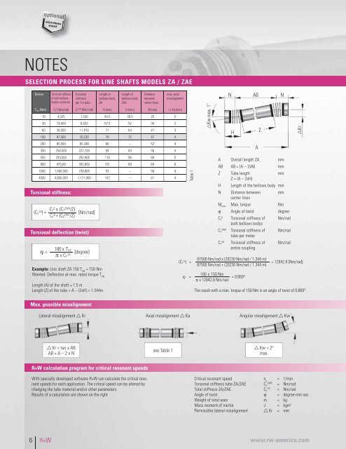
SELECTION PROCESS FOR <strong>LINE</strong> <strong>SHAFTS</strong> MODELS ZA / ZAE<br />
Series<br />
Torsional stiffness<br />
of both bellows<br />
bodies combined<br />
Torsional<br />
stiffness<br />
per 1m tube<br />
Length of<br />
bellows body<br />
ZA<br />
Length of<br />
bellows body<br />
ZAE<br />
Distance<br />
between<br />
center lines<br />
max. axial<br />
misalignment<br />
T KN (Nm)<br />
B<br />
C T (Nm/rad)<br />
ZWR<br />
C T (Nm 2 /rad) H (mm) H (mm) N (mm) Ka (mm)<br />
10 4,525 1,530 44.5 39.5 25 2<br />
30 19,500 6,632 57.5 52 34 2<br />
60 38,000 11,810 71 64 41 3<br />
150 87,500 20,230 78 72 47 4<br />
200 95,500 65,340 86 – 52 4<br />
300 250,500 222,700 94 83 56 4<br />
500 255,000 292,800 110 96 66 5<br />
800 475,00 392,800 101 89 64 6<br />
1500 1,400,000 728,800 92 – 56 4<br />
4000 4,850,000 1,171,000 102 – 61 4<br />
Torsional stiffness:<br />
Torsional deflection (twist)<br />
Table 1<br />
A Overall length ZA mm<br />
AB AB = (A – 2xN) mm<br />
Z Tube length mm<br />
Z = (A – 2xH)<br />
H Length of the bellows body mm<br />
N Distance between mm<br />
center lines<br />
M max Max. torque Nm<br />
ϕ Angle of twist degree<br />
C<br />
B<br />
T Torsional stiffness of Nm/rad<br />
both bellows bodys<br />
C<br />
ZWR<br />
T Torsional stiffness of Nm/rad<br />
tube per meter<br />
C<br />
ZA<br />
T Torsional stiffness of Nm/rad<br />
entire coupling<br />
Example: Line shaft ZA 150 T KN<br />
= 150 Nm<br />
Wanted: Deflection at max. rated torque T KN<br />
Length (A) of the shaft = 1.5 m<br />
Length (Z) of the tube = A – (2xH) = 1.344m<br />
The result with a max. torque of 150 Nm is an angle of twist of 0.669°.<br />
Max. possible misalignment<br />
Lateral misalignment Kr Axial misalignment Ka Angular misalignment Kw<br />
Kr = tan x AB<br />
AB = A – 2 x N<br />
see Table 1<br />
Kw = 2°<br />
max.<br />
R+W calculation program for critical resonant speeds<br />
With specially developed software R+W can calculate the critical resonant<br />
speeds for each application. The critical speed can be altered by<br />
changing the tube material and/or other parameters.<br />
Results of a calculation are shown on the right<br />
Critical resonant speed n k<br />
= 1/min.<br />
Torsional stiffness tube ZA/ZAE<br />
ZWR<br />
C T<br />
= Nm/rad<br />
Total stiffness ZA/ZAE<br />
ZA<br />
C T<br />
= Nm/rad<br />
Angle of twist ϕ = degree-min-sec<br />
Weight of total axes m = kg<br />
Mass moment of inertia J = kgm 2<br />
Permissible lateral misalignment Kr = mm<br />
6<br />
R+W<br />
www.rw-america.com