LINE SHAFTS - Jens S. Transmissioner A/S
LINE SHAFTS - Jens S. Transmissioner A/S
LINE SHAFTS - Jens S. Transmissioner A/S

You also want an ePaper? Increase the reach of your titles
YUMPU automatically turns print PDFs into web optimized ePapers that Google loves.
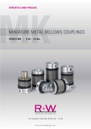
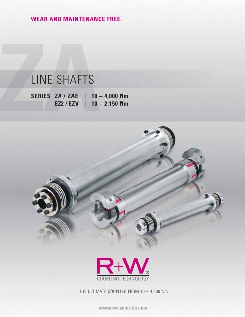
WEAR AND MAINTENANCE FREE.<br />
<strong>LINE</strong> <strong>SHAFTS</strong><br />
SERIES ZA / ZAE<br />
EZ2 / EZV<br />
| 10 – 4,000 Nm<br />
| 10 – 2,150 Nm<br />
THE ULTIMATE COUPLING FROM 10 – 4,000 Nm<br />
www.rw-america.com
TORSION RESISTANT <strong>LINE</strong> <strong>SHAFTS</strong><br />
Application Examples:<br />
Spanning of larger axial distances<br />
■ Palletizers<br />
■ Screw jack systems<br />
■ Multi-axis linear modules<br />
■ Printing machinery<br />
■ Pulp and paper machinery<br />
■ Packaging machinery<br />
■ Conveyor systems<br />
■ Textile machinery<br />
■ Crane gantry systems<br />
■ Automated assembly systems<br />
■ Woodworking machinery<br />
■ Food processing machinery<br />
MODEL PROPERTIES APPLICATION EXAMPLES<br />
ZA<br />
from 10 – 800 Nm<br />
■ Mounting + dismounting without<br />
moving the aligned shafts<br />
■ Standard lengths up to 6 m (19.68 ft.)<br />
■ No intermediate bearing<br />
support required<br />
see page 3<br />
ZA<br />
from 1,500 – 4,000 Nm<br />
■ Mounting + dismounting without<br />
moving the aligned shafts<br />
■ Standard lengths up to 3 m (9.84 ft.)<br />
■ No intermediate bearing<br />
support required<br />
see page 4<br />
ZAE<br />
from 10 – 800 Nm<br />
■ Coupling radially removable<br />
■ easy mounting and dismounting<br />
with split hubs<br />
■ Standard lengths up to 6 m (19.68 ft.)<br />
■ No intermediate bearing support required<br />
Machine<br />
Motor<br />
see page 5<br />
EZ 2<br />
line shaft with split clamping hub<br />
■ vibration damping<br />
■ easy mounting and dismounting<br />
with split hubs<br />
■ length up to 4 m (13.12 ft.)<br />
■ no intermediate bearing<br />
support required<br />
■ radial mounting due to split hubs<br />
Machine<br />
Motor<br />
see page 8<br />
EZV<br />
from 10 – 800 Nm<br />
■ continuously adjustable within length range<br />
■ vibration damping<br />
■ easy mounting and dismounting<br />
with split hubs<br />
■ length up to 4 m (13.12 ft.)<br />
■ no intermediate bearing support required<br />
■ radial mounting due to split hubs<br />
see page 9<br />
2 R+W<br />
www.rw-america.com
MODEL ZA 10-800 Nm<br />
BACKLASH FREE <strong>LINE</strong> <strong>SHAFTS</strong><br />
with clamping hub<br />
Ø B<br />
Ø D 1<br />
H7<br />
H<br />
N<br />
G<br />
C<br />
Ordering example<br />
Ø M<br />
Model<br />
Series/rated torque<br />
Overall length<br />
Ø D1 H7<br />
Ø D2 H7<br />
Non-Standard e.g. carbon tube<br />
I<br />
LK Ø L<br />
All data is subject to change without notice.<br />
J ISO 4762<br />
A -2<br />
F<br />
Ø K<br />
E ISO 4762<br />
Keyway optional<br />
ZA / 10 / 1551 / 18 / 19.05 /XX<br />
H<br />
I<br />
N<br />
C<br />
G<br />
Ø D 2<br />
H7<br />
Properties:<br />
Material:<br />
■ Compensation for misalignment<br />
■ Backlash-free and torsionally rigid<br />
■ Able to span long distances<br />
■ Standard lengths up to 6 m (19.68 ft.)<br />
■ No intermediate bearing support required<br />
■ Intermediate tube removable for easy mounting<br />
■ Bellows made of flexible high grade stainless<br />
steel<br />
■ Aluminum intermediate tube section through<br />
size 200, size 300 and up steel<br />
Optional composite CFK tube<br />
■ Clamping hubs through size 60 aluminum; size<br />
150 and up steel<br />
Design:<br />
■ Balanced clamping hubs with one radial screw<br />
per ISO 4762<br />
■ Intermediate tube section supported by gimbals<br />
within the clamping hub<br />
■ Mounting and dismounting accomplished<br />
through the removal of the intermediate tube<br />
section<br />
Temperature<br />
range: -30 to +100° C (-22˚ F to 212˚ F)<br />
Speed: Depending on length A, please contact R+W<br />
Service life:<br />
Backlash:<br />
Fit tolerance:<br />
These couplings have an infinite life and are maintenance-free<br />
if the technical ratings are not exceeded.<br />
Absolutely backlash-free due to frictional clamp<br />
connection<br />
Shaft/hub connection 0.01 to 0.05 mm<br />
Model ZA 10 - 800 Nm<br />
Series<br />
10 30 60 150 200 300 500 800<br />
Rated torque (Nm) T KN<br />
10 30 60 150 200 300 500 800<br />
Overall length min. to max. (mm) A 110 to 6,000 140 to 6,000 170 to 6,000 190 to 6,000 210 to 6,000 250 to 6,000 260 to 6,000 260 to 6,000<br />
Outer diameter clamping hub (mm) B 40 55 66 81 90 110 123 134<br />
Fit length (mm) C 16 27 31 35.5 40.5 43 50 48<br />
Inner diamter<br />
from Ø to Ø H7<br />
(mm)<br />
D 1/2<br />
5 to 20 10 to 28 12 to 32 19 to 42 22 to 45 30 to 60 35 to 60 40 to 72<br />
With keyway max. Ø H7 (mm) D 1/2<br />
17 23 29 36 45 60 60 66<br />
ISO 4762 clamping screw<br />
M4 M6 M8 M10 M12 M12 M16 2x M16<br />
E<br />
Tightening torque (Nm) 5 15 40 70 110 130 200 250<br />
Distance between centers (mm) F 15 19 23 27 31 39 41 48<br />
Distance (mm) G 5 7.5 9.5 11 12.5 13 17 18<br />
Length bellows body (mm) H 44.5 57.5 71 78 86 94 110 101<br />
Distance (mm) I 38.5 51 61 69 75.5 81 96 89<br />
ISO 4762 screw<br />
4x M4 6x M4 6x M5 8x M6 8x M6 8x M8 8x M8 10x M8<br />
Tightening torque of the<br />
J<br />
assembly screws<br />
(Nm)<br />
3 4 7 10 12 30 30 40<br />
Outer diamter tube section (mm) K 35 50 60 76 90 100 110 120<br />
Bolt hole circle Ø (mm) L 45 62.5 71.5 88 100 120 132 138<br />
Outer diamter flange (mm) M 52 70 80 98 110 135 148 153<br />
Shaft average value (mm) N 25 34 41 47 52 56 66 64<br />
1Nm = 8.85 in lbs<br />
max. permissible misalignment page 6<br />
www.rw-america.com<br />
R+W 3
MODEL ZA 1500-4000 Nm<br />
BACKLASH FREE <strong>LINE</strong> <strong>SHAFTS</strong><br />
with tapered conical sleeves<br />
Ø B<br />
Ø D 1<br />
H7<br />
N<br />
C<br />
I<br />
H<br />
Ø M<br />
LK Ø L<br />
Ordering example<br />
J ISO 4762<br />
A -2<br />
Ø K<br />
H<br />
I<br />
N<br />
C<br />
3x hub removal<br />
screws<br />
E ISO 4762<br />
ZA / 1500 / 2551 / 65 / 70 / XX<br />
Ø D 2<br />
H7<br />
Properties:<br />
Material:<br />
■ Compensation for misalignment<br />
■ Backlash-free and torsionally rigid<br />
■ Able to span long distances<br />
■ Standard lengths up to 3 m (9.84 ft)<br />
■ No intermediate bearing support required<br />
■ Intermediate tube removable for easy mounting<br />
■ Bellows made of flexible high grade stainless<br />
steel<br />
■ Intermediate tube section: steel,<br />
optional composite CFK tube<br />
■ Clamping hubs: steel<br />
Design:<br />
■ With tapered conical sleeves and captive jack<br />
screws<br />
■ Intermediate tube section supported by gimbals<br />
within the clamping hub.<br />
■ Lateral mounting and dismounting accomplished<br />
through the removal of the intermediate tube<br />
section.<br />
Temperature<br />
range: -30 to +100° C (-22˚ F to 212˚ F)<br />
Speed:<br />
Depending on length A, please contact R+W<br />
Model<br />
Series/rated torque<br />
Overall length<br />
Ø D1 H7<br />
Ø D2 H7<br />
Non-Standard e.g. carbon tube<br />
Service life:<br />
Backlash:<br />
Fit tolerance:<br />
These couplings have an infinite life and are maintenance-free<br />
if the technical ratings are not exceeded<br />
Absolutely backlash-free due to frictional clamp<br />
connection<br />
Shaft/hub connection 0.01 to 0.05 mm<br />
All data is subject to change without notice.<br />
Model ZA 1500 - 4000 Nm<br />
Series<br />
1500 4000<br />
Rated torque (Nm) T KN<br />
1500 4000<br />
Overall length min. to max. (mm) A 280 to 6,000 280 to 6,000<br />
Quter diameter (mm) B 157 200<br />
Fit length (mm) C 61 80,5<br />
Inner diameter<br />
from Ø to Ø H7<br />
(mm)<br />
D 1/2<br />
35 to 70 40 to 100<br />
ISO 4017 clamping screws 6x<br />
M12<br />
M16<br />
E<br />
Tightening torque (Nm) 70 120<br />
Length bellows body (mm) H 98 103,5<br />
Distance (mm) I 82 84<br />
ISO 4762 screw<br />
10x M10<br />
12x M12<br />
Tightening torque of the<br />
J<br />
assembly screws<br />
(Nm)<br />
70 120<br />
Outer diameter tube section (mm) K 150 160<br />
Bolt hole circle Ø (mm) L 168 193<br />
Outer diameter flange (mm) M 184 213<br />
Shaft average value (mm) N 56 61<br />
Vertical installation ZA/ZAE<br />
■ When mounting vertically,<br />
additional support of the<br />
lower bellows body is necessary.<br />
■ A special bellows body for vertical<br />
mounting is available upon<br />
request.<br />
■ Please note „vertical mounting“<br />
when ordering.<br />
max. permissible misalignment page 6<br />
4 R+W<br />
www.rw-america.com
MODEL ZAE 10-800 Nm<br />
BACKLASH FREE <strong>LINE</strong> <strong>SHAFTS</strong><br />
Ø B<br />
Ø D 1<br />
H7<br />
I<br />
O<br />
C<br />
H<br />
N<br />
G<br />
Ordering example<br />
Model<br />
Series/rated torque<br />
Overall length<br />
Ø D1 H7<br />
Ø D2 H7<br />
Non-Standard e.g. carbon tube<br />
Ø K<br />
All data is subject to change without notice.<br />
F<br />
A -2<br />
F<br />
H<br />
N<br />
E ISO 4762<br />
I<br />
O<br />
C<br />
Keyway optional<br />
ZAE / 10 / 1551 /18 /19.05/XX<br />
G<br />
Ø D 2<br />
H7<br />
Properties:<br />
Material:<br />
Design:<br />
with split hub<br />
■ Compensation for misalignment<br />
■ Backlash-free and torsionally rigid<br />
■ Able to span long distances<br />
■ Standard lengths up to 6 m (19.68 ft)<br />
■ No intermediate bearing support required<br />
■ Split hubs for easy mounting and dismounting<br />
■ Bellows made of flexible high grade stainless<br />
steel<br />
■ Aluminum intermediate tube section through<br />
size 150, size 300 and up steel<br />
optional composite CFK tube<br />
■ Clamping hubs through size 60 aluminum; size<br />
150 and up steel<br />
■ Balanced split clamping hubs with two radial<br />
clamping screws ISO 4762<br />
■ Intermediate tube section supported by<br />
gimbals within the bellows<br />
■ Lateral mounting and dismounting<br />
accomplished due to split hubs<br />
Temperature<br />
range: -30 to +100° C (-22˚ F to 212˚ F)<br />
Speed: Depending on length A, please contact R+W<br />
Service life:<br />
Backlash:<br />
Fit tolerance:<br />
These couplings have an infinite life and are maintenance-free<br />
if the technical ratings are not exceeded.<br />
Absolutely backlash-free through frictional clamp<br />
connection<br />
Shaft/hub connection 0.01 to 0.05 mm<br />
Model ZAE 10 - 800 Nm<br />
Series<br />
10 30 60 150 300 500 800<br />
Rated torque (Nm) T KN<br />
10 30 60 150 300 500 800<br />
Overall length min. to max. (mm) A 100 to 6,000 130 to 6,000 160 to 6,000 180 to 6,000 240 to 6,000 250 to 6,000 250 to 6,000<br />
Outer diameter clamping hub (mm) B 40 55 66 81 110 123 133<br />
Fit length (mm) C 16 27 31 34.5 42 50 47<br />
Inner diamter<br />
from Ø to Ø H7<br />
(mm)<br />
D 1/2<br />
5 to 20 10 to 28 12 to 32 19 to 42 30 to 60 35 to 60 40 to 72<br />
Max.inner diameter<br />
clamping hub<br />
(mm)<br />
D max<br />
24 30 32 42 60 60 75<br />
with keyway - max Ø H7 (mm) D 1/2<br />
17 23 29 36 60 60 66<br />
ISO 4762 clamping screws<br />
M4 M6 M8 M10 M12 M16 M16<br />
E<br />
Tightening torque (Nm) 5 15 40 70 130 200 250<br />
Distance between centers (mm) F 15 19 23 27 39 41 48<br />
Distance (mm) G 5 7.5 9.5 12 14 17 19<br />
Length bellows body (mm) H 39.5 52 64 72 83 96 95<br />
Clamping length (mm) I 10 15 19 22 28 33.5 37.5<br />
Outer diameter tube section (mm) K 35 50 60 76 100 110 120<br />
Length (mm) O 11.5 17 21 24 30 35 40<br />
Shaft average value (mm) N 25 34 41 47 56 66 65<br />
1Nm = 8.85 in lbs<br />
www.rw-america.com<br />
max. permissible misalignment page 6<br />
R+W 5
NOTES<br />
SELECTION PROCESS FOR <strong>LINE</strong> <strong>SHAFTS</strong> MODELS ZA / ZAE<br />
Series<br />
Torsional stiffness<br />
of both bellows<br />
bodies combined<br />
Torsional<br />
stiffness<br />
per 1m tube<br />
Length of<br />
bellows body<br />
ZA<br />
Length of<br />
bellows body<br />
ZAE<br />
Distance<br />
between<br />
center lines<br />
max. axial<br />
misalignment<br />
T KN (Nm)<br />
B<br />
C T (Nm/rad)<br />
ZWR<br />
C T (Nm 2 /rad) H (mm) H (mm) N (mm) Ka (mm)<br />
10 4,525 1,530 44.5 39.5 25 2<br />
30 19,500 6,632 57.5 52 34 2<br />
60 38,000 11,810 71 64 41 3<br />
150 87,500 20,230 78 72 47 4<br />
200 95,500 65,340 86 – 52 4<br />
300 250,500 222,700 94 83 56 4<br />
500 255,000 292,800 110 96 66 5<br />
800 475,00 392,800 101 89 64 6<br />
1500 1,400,000 728,800 92 – 56 4<br />
4000 4,850,000 1,171,000 102 – 61 4<br />
Torsional stiffness:<br />
Torsional deflection (twist)<br />
Table 1<br />
A Overall length ZA mm<br />
AB AB = (A – 2xN) mm<br />
Z Tube length mm<br />
Z = (A – 2xH)<br />
H Length of the bellows body mm<br />
N Distance between mm<br />
center lines<br />
M max Max. torque Nm<br />
ϕ Angle of twist degree<br />
C<br />
B<br />
T Torsional stiffness of Nm/rad<br />
both bellows bodys<br />
C<br />
ZWR<br />
T Torsional stiffness of Nm/rad<br />
tube per meter<br />
C<br />
ZA<br />
T Torsional stiffness of Nm/rad<br />
entire coupling<br />
Example: Line shaft ZA 150 T KN<br />
= 150 Nm<br />
Wanted: Deflection at max. rated torque T KN<br />
Length (A) of the shaft = 1.5 m<br />
Length (Z) of the tube = A – (2xH) = 1.344m<br />
The result with a max. torque of 150 Nm is an angle of twist of 0.669°.<br />
Max. possible misalignment<br />
Lateral misalignment Kr Axial misalignment Ka Angular misalignment Kw<br />
Kr = tan x AB<br />
AB = A – 2 x N<br />
see Table 1<br />
Kw = 2°<br />
max.<br />
R+W calculation program for critical resonant speeds<br />
With specially developed software R+W can calculate the critical resonant<br />
speeds for each application. The critical speed can be altered by<br />
changing the tube material and/or other parameters.<br />
Results of a calculation are shown on the right<br />
Critical resonant speed n k<br />
= 1/min.<br />
Torsional stiffness tube ZA/ZAE<br />
ZWR<br />
C T<br />
= Nm/rad<br />
Total stiffness ZA/ZAE<br />
ZA<br />
C T<br />
= Nm/rad<br />
Angle of twist ϕ = degree-min-sec<br />
Weight of total axes m = kg<br />
Mass moment of inertia J = kgm 2<br />
Permissible lateral misalignment Kr = mm<br />
6<br />
R+W<br />
www.rw-america.com
ASSEMBLY INSTRUCTIONS<br />
Alignment<br />
R+W ZA and ZAE line shaft couplings are available in lengths up to 6 meters (19.7 feet) without intermediate bearing support required. Proper alignment is<br />
necessary to ensure maximum life. We recommend laser alignment whenever possible. Other alignment techniques are also appropriate as long as the maximum<br />
permissible misalignment values listed on page 6 are not exceeded.<br />
Clamping hub<br />
■ Model ZA (series 10 - 800 Nm)<br />
■ Model ZAE (series 10 - 800 Nm)<br />
J<br />
Mounting: Loosen screw E and slide the metal bellows coupling segments onto each<br />
shaft end. Now insert the intermediate tube and assemble onto both metal bellows<br />
coupling segments using the assembly screws J. Tighten the assembly screws J to the<br />
correct torque indicated in the specification table. Center the entire line shaft coupling<br />
onto the shaft ends and tighten screw E by using a torque wrench to ensure the correct<br />
torque as indicated in the specification table.<br />
Dismounting: Loosen screw E on one end of the line shaft coupling. Remove<br />
assembly screws J on both ends of the line shaft and remove the intermediate tube.<br />
Be sure to support the intermediate tube during removal. Depending on length this may<br />
require two people. Loosen screw E on the second metal bellows coupling segment<br />
and slide both segments off.<br />
Mounting: First ensure that the distance between shaft ends exceeds the<br />
dimension P.<br />
Length P = length A - 2 x 0 [mm]<br />
Machine<br />
Motor<br />
Insert the line shaft coupling and assemble the split hubs with assembly scews E.<br />
Using a torque wrench to tighten screws E to the correct torque indicated in the<br />
specification table.<br />
Dismounting: Remove the split hubs by removing the assembly screws E. Lift the line<br />
shaft coupling off the shaft ends.<br />
Conical sleeve<br />
■ Model ZA (series 1500 - 4000 Nm)<br />
Mounting: Loosen screws E (Do not remove!) and slide the metal bellows coupling<br />
segments onto each shaft end. Now insert the intermediate tube and assemble onto<br />
both metal bellows coupling segments by using the assembly screws J. Tighten the<br />
assembly screws J to the correct torque which is indicated in the specification table.<br />
Center the entire line shaft coupling onto the shaft ends and evenly tighten screws E<br />
while using a torque wrench. Ensure the correct torque is applied as indicated in the<br />
specification table. Even tightening of screws E is critical to ensure that the shaft and<br />
metal bellows coupling segment are parallel.<br />
CAUTION! An over tightening of the screws E may destroy the<br />
tapered bushing connection. Do not exceed the tightening torque<br />
listed in the specification table.<br />
Dismounting: Loosen the scews E on one side of the line shaft coupling. Use the three jack screws F to loosen the tapered segment so that it slides freely on<br />
the shaft. Remove the assembly screws J from both sides of the coupling and remove the intermediate tube. Ensure that the tube ist supported during removal.<br />
Depending on the length of the tube this may require two people. Repeat the earlier procedure to remove the second metal bellows coupling segment.<br />
CAUTION! Be sure to lower the jack screws F before reassembly.<br />
Maintenance<br />
R+W line shafts are maintenance free. During routine maintenance the line shafts should be visibly inspected.<br />
www.rw-america.com<br />
R+W 7
MODEL EZ2<br />
BACKLASH FREE <strong>LINE</strong> <strong>SHAFTS</strong><br />
with split clamping hubs<br />
G<br />
2 x E ISO 4762<br />
A<br />
C<br />
F<br />
ØBS<br />
F<br />
Properties:<br />
■ Radial mounting possible with split hubs<br />
■ Spans distances of up to 4 m (13.12 ft)<br />
■ No intermediate bearing support required<br />
■ Low moment of inertia<br />
■ Damps vibration<br />
■ Press-fit design<br />
■ Backlash-free<br />
ØB1<br />
ØD1 H7<br />
ØB2<br />
P<br />
O<br />
ØD2 H7<br />
DIN 6885 or inch<br />
Keyway optional<br />
Material:<br />
Clamping hub: up to series 450 high strength<br />
aluminum, from series 800 and up steel<br />
Elastomer insert: precision molded, wear resistant,<br />
and thermally stable polymer<br />
Intermediate tube: precision machined aluminum<br />
tube; steel and composite tubes are<br />
also available<br />
Ordering example<br />
Model<br />
Series<br />
Overall length<br />
Type Elastomer insert<br />
Bore Ø D1 H7<br />
Bore Ø D2 H7<br />
Non standard e.g. finely balanced<br />
EZ2 / 020 / 1200 / A / 24 / 19.05 / XX<br />
Design:<br />
Speed:<br />
Tolerance:<br />
Two coupling hubs are concentrically machined<br />
with concave driving jaws<br />
Elastomer inserts are available in type A or B<br />
The two coupling elements are connected<br />
with a precise and concentrically machined<br />
aluminum tube<br />
Please advise the application speed when<br />
ordering or inquiring about EZ Line shafts<br />
On the hub/shaft connection 0.01 to 0.05 mm<br />
All data is subject to change without notice.<br />
Series<br />
Model EZ 2<br />
10 20 60 150 300 450 800<br />
Type (Elastomer insert) A B A B A B A B A B A B A B<br />
Rated torque (Nm) T KN<br />
12,5 16 17 21 60 75 160 200 325 405 530 660 950 1100<br />
Max. torque** (Nm) T Kmax<br />
25 32 34 42 120 150 320 400 650 810 1060 1350 1900 2150<br />
Overall length (mm) A 95 - 4, 000 130 - 4 ,000 175 - 4 ,000 200 - 4, 000 245 - 4, 000 280 - 4 ,000 320 - 4, 000<br />
Outer diameter hub (mm) B 1<br />
32 42 56 66.5 82 102 136.5<br />
Outer diameter tube (mm) B 2<br />
28 35 50 60 76 90 120<br />
Outer diameter with screwhead (mm) B S<br />
32 44.5 57 68 85 105 139<br />
Fit length (mm) C 20 25 40 47 55 65 79<br />
Inner diameter range from Ø to Ø H7 (mm) D 1/2<br />
5 - 16 8 - 25 14 - 32 19 - 36 19 - 45 24 - 60 35 - 80<br />
Mounting screw (ISO 4762/12.9)<br />
M4 M5 M6 M8 M10 M12 M16<br />
Tightening torque of the<br />
E<br />
mounting screw<br />
(Nm)<br />
4 8 15 35 70 120 290<br />
Distance between centers (mm) F 10.5 15.5 21 24 29 38 50.5<br />
Distance (mm) G 7.5 8.5 15 17.5 20 25 30<br />
Mounting length (mm) O 16.6 18.6 32 37 42 52 62<br />
Moment of inertia per hub half (10 -3 kgm 2 ) J 1<br />
/J 2<br />
0.01 0.02 0.15 0.21 1.02 2.3 17<br />
Inertia of tube per meter (10 -3 kgm 2 ) J 3<br />
0.075 0.183 0.66 1.18 2.48 10.6 38<br />
** Max. transferable torque of the clamping hub see table 3 (page 10)<br />
8 R+W<br />
www.rw-america.com
MODEL EZV<br />
BACKLASH FREE <strong>LINE</strong> <strong>SHAFTS</strong><br />
variable length<br />
ØB1<br />
ØD1 H7<br />
G<br />
A min. / A max.<br />
2 x E1 ISO 4762 2 x E2 ISO 4762 C<br />
ØD2 H7<br />
ØBS<br />
Properties:<br />
■ Lateral mounting due to split hubs<br />
■ Spans distances of up to 4 m (13.12 ft)<br />
■ Low moment of inertia<br />
■ Vibration damping<br />
■ Press fit designs<br />
■ Backlash free line shaft<br />
Machine<br />
Ordering example<br />
ØB2<br />
Model<br />
Series<br />
inserted min. length<br />
Type Elastomer insert<br />
Bore Ø D1 H7<br />
Bore Ø D2 H7<br />
Non standard e.g. finely balanced<br />
ØB3<br />
P min. / P max.<br />
ref. A<br />
F1 F1 F2 F2<br />
ref. A<br />
Motor<br />
ref. A<br />
EZV / 020 / 1200 / A / 24 / 19 / XX<br />
Material:<br />
Design:<br />
Speed:<br />
Tolerance:<br />
Clamping hub: high strength aluminum.<br />
Elastomer insert: precision molded wear<br />
resistant, and thermally stable polymer.<br />
Intermediate tubes: precision machined<br />
aluminum tube, steel or composite tube<br />
are available upon request.<br />
Two split coupling hubs are concentrically<br />
machined with concave driving jaws.<br />
Both coupling bodies are rigidly mounted to tubes<br />
with high concentricity. After loosening the tube<br />
clamping, a length variation is possible within the<br />
given range. Elastomer inserts are available in<br />
type A or B.<br />
To find out about the critical resonant speed please<br />
advise the application speed when ordering or<br />
inquiring about EZV line shafts.<br />
On the hub/shaft connection 0.01 to 0.05 mm.<br />
All data is subject to change without notice.<br />
Series<br />
Model EZV<br />
10 20 60 150 300 450<br />
Type (Elastomer insert) A B A B A B A B A B A B<br />
Rated torque (Nm) T KN<br />
12.5 16 17 21 60 75 160 200 325 405 530 660<br />
Max. torque** (Nm) T Kmax<br />
25 32 34 42 120 150 320 400 650 810 1060 1200<br />
Inserted min. length<br />
from - to<br />
(mm)<br />
A min<br />
150 to 2, 055 200 to 2, 075 250 to 2, 095 300 to 2 ,115 350 to 2 ,130 400 to 2, 150<br />
Extended over all length<br />
from - to<br />
(mm)<br />
A max<br />
190 to 4 000 250 to 4 000 310 to 4 000 370 to 4 000 440 to 4 000 500 to 4 000<br />
Outer diameter hub (mm) B 1<br />
32 42 56 66.5 82 102<br />
Outer diameter tube (mm) B 2<br />
28 35 50 60 80 90<br />
Outer diameter with screwhead (mm) B S<br />
32 44.5 57 68 85 105<br />
Fit length (mm) C 20 25 40 47 55 65<br />
Inner diameter possible from<br />
Ø to Ø H7<br />
(mm)<br />
D 1/2<br />
5 to 16 8 to 25 14 to 32 19 to 35 19 to 45 24 to 60<br />
Screw (ISO 4762/12.9)<br />
M4 M5 M6 M8 M10 M12<br />
E<br />
Tighting torque of the mounting screw (Nm) 1<br />
4 8 15 35 70 120<br />
Distance between centers (mm) F 1<br />
10.5 15.5 21 24 29 38<br />
Distance between centers (mm) F 2<br />
15 18 26 31 41 45<br />
Distance (mm) G 7.5 8.5 15 17.5 20 25<br />
Mounting length (mm) O 16.6 18.6 32 37 42 52<br />
Moment of inertia coupling half (10 -3 kgm 2 ) J 1<br />
/J 2<br />
0.01 0.02 0.15 0.21 1.02 2.3<br />
Inertia of tube per meter (10 -3 kgm 2 ) J 3<br />
0.075 0.183 0.66 1.18 2.48 10.6<br />
Measurement (mm) X1+X2 110 150 190 230 270 300<br />
** Max. transferable torque of the clamping hub see table 3 (page 10)<br />
www.rw-america.com<br />
R+W 9
NOTES<br />
TECHNICAL SPECIFICATIONS<br />
Series<br />
Torsional<br />
stiffness of<br />
both coupling<br />
parts elastomer<br />
insert A<br />
Torsional<br />
stiffness of<br />
both coupling<br />
parts elastomer<br />
insert B<br />
Torsional<br />
stiffness per<br />
1 m tube<br />
Length of the<br />
coupling EZ<br />
Distance<br />
between<br />
center lines<br />
Max. axial<br />
misalignment<br />
T KN (Nm) C T<br />
B<br />
(Nm/rad) C T<br />
B<br />
(Nm/rad) C T<br />
ZWR<br />
(Nm/rad) H (mm) N (mm) Ka (mm)<br />
r<br />
10 270 825 321 34 26 2<br />
20 1270 2220 1530 46 33 4<br />
60 3970 5950 6632 63 49 4<br />
150 6700 14650 11810 73 57 4<br />
300 11850 20200 20230 86 67 4<br />
450 27700 40600 65340 99 78 4<br />
800 41300 90000 392800 125 94 4<br />
Torsional stiffness<br />
Angle of twist<br />
Table 2<br />
A Overall length m<br />
AB Length AB = (A – 2xN) m<br />
Z Tube length m<br />
Z = (A – 2xH)<br />
H Length of the coupling mm<br />
N Distance between center lines mm<br />
T AS<br />
Max. torque Nm<br />
ϕ Angle of twist degree<br />
E<br />
C Tdyn<br />
Torsional stiffness of both<br />
elastomer inserts<br />
Nm/rad<br />
ZWR<br />
C T<br />
Torsional stiffness of tube Nm/rad<br />
per meter<br />
Torsional stiffness of entire coupling Nm/rad<br />
C Tdyn<br />
EZ<br />
Example: Line shaft EZ2, series 150 T AS<br />
= 160 Nm<br />
To search: Angle of twist at maximal rated torque T AS<br />
Length (A) of the shaft = 1.5 m<br />
Length (Z) of the tube = A – (2xH) = 1.354 m<br />
The result with a max. torque of 160 Nm in an angle of twist of 2.42°<br />
Max. possible misalignment<br />
Lateral misalignment Δ Kr<br />
Angular misalignment Δ Kw<br />
Axial misalignment Δ Ka total<br />
Δ Kr max = tan Δ Kw · AB<br />
2<br />
AB = A – 2xN<br />
Δ Kw max<br />
= ca. 2˚ See table 2<br />
Series Ø 5 Ø 8 Ø 16 Ø 19 Ø 25 Ø 30 Ø 32 Ø 35 Ø 45 Ø 50 Ø 55 Ø 60 Ø 65 Ø 70 Ø 75 Ø 80<br />
10 4 12 32<br />
20 30 40 50 65<br />
60 65 120 150 180 200<br />
150 180 240 270 300 330<br />
300 300 340 450 520 570 630<br />
450 630 720 770 900 1120 1180 1350<br />
800 1050 1125 1200 1300 1400 1450 1500 1550 1600<br />
Table 3<br />
Temperature factor S in ˚ Celsius<br />
Temperature (υ) Sh 98 A Sh 64 D<br />
> -30° to -10° 1.5 1.7<br />
> -10° to +30° 1.0 1.0<br />
> +30° to +40° 1.2 1.1<br />
> +40° to +60° 1.4 1.3<br />
> +60° to +80° 1.7 1.5<br />
> +80° to +100° 2.0 1.8<br />
> +100° to +120° – 2.4<br />
Please note for every design (see brochure EK).<br />
1˚ C = 33,8˚ F<br />
Table 4<br />
10<br />
R+W<br />
www.rw-america.com
ASSEMBLY INSTRUCTIONS<br />
Function<br />
Extended overall length = (Inserted overall length x 2) - Measurement (X1 + X2)<br />
Extended over all length<br />
Clambing hub with tube fixation<br />
Static tube<br />
Variable tube<br />
The extended overall length and the inserted over all<br />
length are related. Depending on the requirements, the<br />
coupling length can be calculated using the two formulas<br />
shown here to receive the extended or the inserted<br />
overall length.<br />
X1<br />
Inserted over all length<br />
X2<br />
Inserted overall length =<br />
Extended over all length + Measurement ( X1 + X2 )<br />
2<br />
Alignment<br />
To ensure maximum life proper alignment is necessary. We recommend laser alignment whenever possible. Other alignment techniques are also appropriate<br />
as long as the maximum permissible misalignment values listed on table 2 (page 10) are not exceeded.<br />
Specification of the elastomer inserts<br />
Type Shore hardness Color Material<br />
Relative<br />
damping (ψ)<br />
Temperature range Features<br />
A 98 Sh A red TPU 0.4 - 0.5 -30°C to +100°C high damping<br />
B 64 Sh D green TPU 0.3 - 0.45 -30°C to +120°C high torsional stiffness<br />
The values of the relative damping were determined at 10 Hz and +20˚ C.<br />
Clamping hub<br />
■ Model EZ2 / EZV<br />
A<br />
0 0<br />
E<br />
Mounting: First ensure that the distance between shaft ends exceeds<br />
dimension P.<br />
Distance P = Length A - 2 x 0 [mm]<br />
Distance P<br />
The total length of the axis is defined by the distance P + 2 x 0.<br />
Insert the line shaft coupling and assemble the split hubs with assembly screws<br />
E. Using a torque wrench to tighten screws E to the correct torque indicated in the<br />
specification table.<br />
Dismounting: Remove the split hubs by removing the assembly screws E.<br />
Lift the line shaft coupling off the shaft ends.<br />
Maintenance<br />
R+W line shafts are maintenance free. During routine maintenance the line shafts should be visibly inspected.<br />
www.rw-america.com<br />
R+W 11
THE R+W-PRODUCT RANGE<br />
TORQUE LIMITERS<br />
Series SK + ST<br />
From 0.1 – 160,000 Nm, Bore diameters 3 – 290 mm<br />
Available as a single position, multi-position,<br />
load holding, or full disengagement version<br />
Single piece or press-fit design<br />
Experience and<br />
Know-how<br />
for your special<br />
requirements.<br />
BELLOWS COUPLINGS<br />
Series BK<br />
From 2 – 10,000 Nm<br />
Bore diameters 10 – 180 mm<br />
Single piece or press-fit design<br />
<strong>LINE</strong> <strong>SHAFTS</strong><br />
Series ZA / ZAE / EZ / EZV<br />
From 10 – 4,000 Nm<br />
Bore diameters 10 – 100 mm<br />
Available up to 6 m length<br />
R+W America<br />
1120 Tower Lane<br />
Bensenville, IL 60106<br />
Phone: 630-521-9911<br />
Fax: 630-521-0366<br />
info@rw-america.com<br />
www.rw-america.com<br />
MINIATURE BELLOWS COUPLINGS<br />
Series MK<br />
From 0.05 – 10 Nm<br />
Bore diameters 1 – 28 mm<br />
Single piece or press-fit design<br />
SERVOMAX ®<br />
ELASTOMER COUPLINGS<br />
Series EK<br />
From 2 – 2,000 Nm, Shaft diameters 3 – 170 mm<br />
backlash-free, press-fit design<br />
ECOLIGHT ®<br />
ELASTOMER COUPLINGS<br />
Series TX 1<br />
From 2 – 810 Nm<br />
Shaft diameters 3 – 45 mm<br />
<strong>LINE</strong>AR COUPLINGS<br />
Series LK<br />
From 70 – 2,000 N<br />
Thread M5 – M16<br />
TGA-ZM-05-91-00<br />
Registration No. 40503432/2<br />
The information mentioned in this document is<br />
based on our present knowledge and experiences<br />
and does not exclude the manufacturer’s own<br />
substantial testing of the equipment. So this is no<br />
obligatry assurance even with regard to protection<br />
rights of Third Parties. The sale of our products<br />
is subject to our General Conditions of Sale and<br />
Delivery.<br />
POLYAMIDE COUPLINGS<br />
MICROFLEX<br />
Series FK 1<br />
Rated torque 1 Ncm<br />
Bore diameters 1 – 1.5 mm<br />
A053/06/10/1.000