Cable Carriers for Track Systems - VAHLE, Inc
Cable Carriers for Track Systems - VAHLE, Inc
Cable Carriers for Track Systems - VAHLE, Inc

Create successful ePaper yourself
Turn your PDF publications into a flip-book with our unique Google optimized e-Paper software.
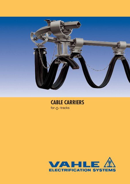
CABLE CARRIERS<br />
<strong>for</strong> -tracks
<strong>VAHLE</strong> FESTOON SYSTEMS<br />
CONTENTS<br />
Page<br />
General in<strong>for</strong>mation 2<br />
Questionnaire 3<br />
Diamond <strong>Track</strong> V 3 and Accessories 4, 5<br />
<strong>Cable</strong> <strong>Carriers</strong> <strong>for</strong> V 3 5<br />
Lead <strong>Carriers</strong> and <strong>Track</strong> Clamps <strong>for</strong> V 3 6<br />
Control <strong>Carriers</strong> and Accessories <strong>for</strong> V 3 7<br />
Example <strong>for</strong> Ordering 8<br />
Installation Tools, diagram 9<br />
Table determining the storage distance and number of carriers 10, 11<br />
General<br />
<strong>VAHLE</strong>-Festoon systems support electric cables or hoses <strong>for</strong> mobile machinery.<br />
The cable carriers contained in this catalog comply with VDE regulations. Diamond tracks are especially well suited <strong>for</strong><br />
curved installations.<br />
Application<br />
<strong>Cable</strong> carriers ride on the square bar parallel to the traversing<br />
track of the equipment. This arrangement ensures that<br />
the total length of equipment (e.g. hoist, crab, trolley, etc.)<br />
is used as storage distance <strong>for</strong> the carriers (see sketch<br />
below). The first carrier (lead carrier) is connected to the<br />
equipment by an outrigger and towed along the diamond<br />
track.<br />
All carriers are connected to each other via the cables or<br />
hoses installed. Depending on the cable/hose package,<br />
the loop, the speed, the acceleration and the type of<br />
curve radii it might be necessary to consider tension relief<br />
elements.<br />
Important <strong>for</strong> proper per<strong>for</strong>mance:<br />
a) Consider min. permissible bending radii of cables<br />
b) Consider a cable loop safety length of 10-15% <strong>for</strong><br />
straight runs and 20% <strong>for</strong> curved tracks.<br />
Layout<br />
The types of cables are determined according to the<br />
required number of conductors and the current load of the<br />
equipment (see cat. 8L). The dimensions of cables are the<br />
basis <strong>for</strong> the selection of the carrier type. The length of<br />
cable results from active travel distance plus storage<br />
distance, extra safety length plus end connections (see<br />
installation in<strong>for</strong>mation).<br />
Consider a multiplier of 0.7 x smallest radius <strong>for</strong> the<br />
maximum permissible cable loop in curved installations.<br />
The maximum permissible speed depends on the total<br />
amount of curve angles.<br />
For systems specification please refer to the example <strong>for</strong><br />
ordering in this catalog.<br />
We welcome your inquiry on your particular application.<br />
Kindly consult your local Vahle agent or the factory using<br />
the questionnaire and submitting a system layout.<br />
2
QUESTIONNAIRE<br />
Name and Adress of Customer:<br />
Ref.:<br />
1. Type of Application<br />
2. Outdoors ■ indoors ■<br />
3. Temperature range ° C min. ° C max.<br />
4. Is round or flat<strong>for</strong>m cable envisaged?<br />
5. How much space is available <strong>for</strong> storage? mm<br />
6. Is it possible to extend the track <strong>for</strong> the festoon cable system in case the length of equipment is insufficient <strong>for</strong> storage space?<br />
■ Yes, by<br />
mm, ■ no, not possible.<br />
7. Special operating conditions:<br />
8. Length of crane trolley: mm<br />
9. Travel distance of crane trolley: mm<br />
10. Travelling speed: m/min.<br />
12. Required cables:<br />
No. of No. & size of ø width x thickness<br />
cables conductors mm of flat<strong>for</strong>m cables<br />
11. Max. loop depth: mm<br />
12. Further details:<br />
Please, submit the completed Questionnaire together with your inquiry. Your system layout drawing will be appreciated in<br />
case of curves.<br />
3
V 3 TRACK AND ACCESSORIES<br />
<strong>Track</strong><br />
Type V 3<br />
Order- No. 360 196<br />
Order- No. <strong>for</strong> bending 360 026<br />
For cable carrier WV 3<br />
Material<br />
steel<br />
Surface protection<br />
galvanized<br />
Supply lengths<br />
6 m<br />
Standard support spacing 2 m (1 m in storage<br />
section and curves)<br />
Moment in inertia Jx 2,94 cm 4<br />
Section modulus Wx 1,39 cm 3<br />
Weight<br />
1,77 kg/m<br />
Other support centers and permissible area loads<br />
Support spacing 1 m 1,5 m 2 m 2,5 m 3 m 3,5 m<br />
perm. area load 111 kg 74 kg 47 kg 30 kg 21 kg 15 kg<br />
Joint clamp<br />
nut torque 10 Nm<br />
End cap<br />
Type VV 3<br />
Type K 30<br />
Order- No. 360 018<br />
Order- No. 360 023<br />
Material<br />
steel/aluminium<br />
Material<br />
polyethylene<br />
Surface protection<br />
galvanized<br />
Weight<br />
0,008 kg<br />
Weight<br />
0,125 kg<br />
Hanger<br />
underhung<br />
Hanger<br />
underhung <strong>for</strong> HK support<br />
Type ADV 3<br />
Order- No. 360 019<br />
Material<br />
steel/aluminium<br />
Surface protection galvanized<br />
Weight<br />
0,11 kg<br />
2 bolts M 6 x 30, order- No. 360 030<br />
to be ordered separately<br />
nut torque 10 Nm<br />
Type AKV 3<br />
Order- No. 360 020<br />
Material<br />
steel/aluminium<br />
Surface protection galvanized<br />
Weight<br />
0,19 kg<br />
nut torque 10 Nm<br />
Support bracket<br />
Dim A depends on width of<br />
machinery (e.g. crane trolley).<br />
Make sure that hoist wheels have<br />
enough clearance.<br />
Type Material Surface Weight A (adjustable) L Order- No.<br />
protection kg mm mm max. B mm<br />
HK 200 0,980 200 400 210 (1) 310 220<br />
HK 300 steel galvanized 1,130 300 500 210 (1) 310 230<br />
HK 400 1,290 400 600 210 (1) 310 240<br />
HK 500 1,430 500 700 210 (1) 310 250<br />
Our delivery: 1 pair of claws and track S1. Hangers AKV 3 to be ordered separately.<br />
4 (1) Select next larger size bracket when your I-beam dimension B is more than 210 mm.
ACCESSORIES AND CABLE CARRIERS FOR V 3 TRACK<br />
Claw <strong>for</strong> HK<br />
Type<br />
SP<br />
Order- No. 310 390<br />
Material<br />
steel<br />
Surface protection galvanized<br />
Weight<br />
0,200 kg<br />
Flat nut M 8 separately available<br />
Order- No. 310 955.<br />
Bracket bars <strong>for</strong> HK<br />
clamping area 0-20 mm<br />
Support Attachment <strong>for</strong> HK<br />
Type AH 1<br />
Order- No. 310 400<br />
Material<br />
steel<br />
Surface protection Hardware<br />
galvanized<br />
Weight<br />
0,460 kg<br />
Bracket bars and hangers to be<br />
ordered separately.<br />
Type Material Surface protection Weight L Order- No.<br />
kg<br />
mm<br />
S 1 - 400 0,620 400 310 600<br />
S 1 - 500 steel galvanized 0,780 500 310 610<br />
S 1 - 600 0,930 600 310 620<br />
S 1 - 700 1,090 700 310 630<br />
<strong>Cable</strong> <strong>Carriers</strong> <strong>for</strong> V 3 <strong>Track</strong><br />
Engineering data<br />
Type WV 3-25 F WV 3-32 F<br />
<strong>for</strong> indoor use<br />
<strong>for</strong> indoor and outdoor use<br />
Wheels Ball bearings ø 25, galvanized Ball bearings Ø 32, galvanized<br />
Z-sealed<br />
RS-sealing<br />
Temperature resistance lub grease: –30° to +125° C Temperature resistance lub grease: –30° C to +125° C<br />
Travelling speed: max. 80 m/min.<br />
Travelling speed: max. 100 m/min.<br />
Material Carrier body: Aluminium<br />
Bumper plates: Steel, galvanized<br />
Support saddle: Steel, galvanized<br />
Hardware: galvanized<br />
Loop depth max. 3.5 m with max. cable load max. 3.5 m with max. cable load,<br />
(max. 20 kg per carrier)<br />
(max. 25 kg/carrier)<br />
<strong>Cable</strong> <strong>Carriers</strong> <strong>for</strong> Flat<strong>for</strong>m <strong>Cable</strong><br />
max. thickness max. clamping A B C D<br />
Type <strong>Cable</strong> of individual capacity in mm Weight Order- No.<br />
cable mm height x width mm kg<br />
WV 3-25 F/50-110<br />
7,9<br />
30 x 65 110 60<br />
50 0,90<br />
360 000<br />
WV 3-25 F/50-140 flat- 45 x 65 140 80<br />
25<br />
360 001<br />
WV 3-25 F/80-110 <strong>for</strong>m<br />
10,0<br />
15 x 65 110 60<br />
80 0,96<br />
360 004<br />
WV 3-25 F/80-140 30 x 65 140 60 360 005<br />
WV 3-32 F/50-110<br />
7,9<br />
30 x 65 110 60<br />
50 1,05<br />
360 002<br />
WV 3-32 F/50-140 flat- 45 x 65 140 80<br />
32<br />
360 003<br />
WV 3-32 F/80-110 <strong>for</strong>m<br />
10,0<br />
15 x 65 110 60<br />
80 1,11<br />
360 006<br />
WV 3-32 F/80-140 30 x 65 140 60 360 007<br />
5
V 3 LEAD CARRIERS AND TRACK CLAMPS3<br />
Lead <strong>Carriers</strong> <strong>for</strong> flat <strong>for</strong>m <strong>Cable</strong><br />
L M<br />
Type <strong>for</strong> <strong>Cable</strong> carriers L M <strong>Cable</strong> A Weight Order- No.<br />
mm<br />
kg<br />
MV 3-25 F/50-110 WV 3-25 F/50-110 55 110<br />
360 008<br />
MV 3-25 F/50-140 WV 3-25 F/50-140 70 flat- 140<br />
1,27<br />
360 009<br />
MV 3-25 F/80-110 WV 3-25 F/80-110 55 <strong>for</strong>m 110<br />
360 012<br />
MV 3-25 F/80-140 WV 3-25 F/80-140 70 140<br />
1,33<br />
360 013<br />
MV 3-32 F/50-110 WV 3-32 F/50-110 55 110<br />
360 010<br />
MV 3-32 F/50-140 WV 3-32 F/50-140 70 flat- 140<br />
1,42<br />
360 011<br />
MV 3-32 F/80-110 WV 3-32 F/80-110 55 <strong>for</strong>m 110<br />
360 014<br />
MV 3-32 F/80-140 WV 3-32 F/80-140 70 140<br />
1,48<br />
360 015<br />
<strong>Track</strong> clamps c/w bumper <strong>for</strong> flat<strong>for</strong>m <strong>Cable</strong><br />
torque moment 10 NM<br />
nut torque 10 Nm<br />
L E<br />
103<br />
140<br />
Type <strong>for</strong> <strong>Cable</strong> carriers L E <strong>Cable</strong> Weight Order- No.<br />
kg<br />
WV 3-25 F/50-110 85<br />
EV 3-F/50<br />
WV 3-25 F/50-140 70<br />
flat<strong>for</strong>m 0,66 360 016<br />
WV 3-32 F/50-110 85<br />
WV 3-32 F/50-140 70<br />
WV 3-25 F/80-110 85<br />
EV 3-F/80<br />
WV 3-25 F/80-140 70<br />
WV 3-32 F/80-110 85<br />
WV 3-32 F/80-140 70<br />
flat<strong>for</strong>m 0,73 360 017<br />
6
V 3 CONTROL CARRIERS AND ACCESSORIES<br />
Control <strong>Carriers</strong><br />
110<br />
435<br />
119<br />
ø32<br />
D E F G<br />
Type<br />
mm<br />
Weight kg Order- No.<br />
ST-V3-32/A1 190 150 38 100 4,9 360 138<br />
ST-V3-32/A2 280 200 62 140 6,3 360 139<br />
50<br />
155<br />
Ausführung<br />
Carrier body: aluminium Support bar: aluminium<br />
Wheels: steel ball bearings Terminal box: noryl<br />
Max. cable load: 25 kg<br />
Temperature resistance: – 30° C to + 100° C<br />
A<br />
max.<br />
terminal block lenght<br />
B<br />
E<br />
C<br />
D<br />
26<br />
F<br />
G<br />
Attention: The junction box is to be grounded with terminal block Type EK 2.5 N PA!<br />
ST-V3-32/A1<br />
<strong>Cable</strong> glands<br />
max.<br />
number<br />
A-Side<br />
max.<br />
number<br />
B-Side<br />
M 20 x 1,5 6 2<br />
M 25 x 1,5 5 1<br />
M 32 x 1,5 3 1<br />
M 40 x 1,5 2 1<br />
M 50 x 1,5 2 1<br />
M 63 x 1,5 - –<br />
ST-V3-32/A2<br />
<strong>Cable</strong> glands<br />
max.<br />
number<br />
A-Side<br />
max.<br />
number<br />
B-Side<br />
M 20 x 1,5 12 6<br />
M 25 x 1,5 10 6<br />
M 32 x 1,5 8 4<br />
M 40 x 1,5 4 2<br />
M 50 x 1,5 3 1<br />
M 63 x 1,5 3 1<br />
Max. length of Terminal block<br />
A1 = 130 mm<br />
A2 = 220 mm<br />
Bumper<br />
required c/w control carriers<br />
nut torque 10 Nm<br />
Type PV 3<br />
Order- No. 360 021<br />
Material<br />
steel/aluminium<br />
Weight<br />
0,49 kg<br />
Strain Relief Chain c/w Accessories<br />
Type<br />
ZEK<br />
Order- No. 360 027<br />
Material<br />
steel<br />
Surface Protection galvanized<br />
Weight kg/m 0,075<br />
S-hook<br />
S-hook<br />
Accessories:<br />
Each piece of chain requires:<br />
2 S-hooks, Order- No. 360 390.<br />
Each <strong>Track</strong> clamp requires:<br />
1 ring screw RS, Order- No. 360 029.<br />
X =<br />
(F x 1,05) + Z<br />
n + 1<br />
X = Chain length in mm<br />
F = Travel distance of lead carrier in mm<br />
n = Number of cable carriers<br />
(w/o lead carriers and end clamps)<br />
1,05 = Safety length factor<br />
Z = Open space in storage section<br />
(see page 11, point 5)<br />
7
EXAMPLE FOR ORDERING<br />
Inquiry: Hoist on track per drawing – Indoor Installation –<br />
Travelling speed:<br />
<strong>Cable</strong>s:<br />
max. <strong>Cable</strong> loop depth:<br />
required hookup cable end connections:<br />
30 m /min.<br />
1 PVC-flat<strong>for</strong>m (K) H 07 VV H 2 - F 4 G 4 (7,1 x 22 mm)<br />
1 PVC-flat<strong>for</strong>m (K) H 07 VV H 2 - F 8 G 2,5 (5,9 x 35,7 mm)<br />
1 m (per structural environment)<br />
1 x 2 m + 1 x 5 m<br />
How to select the correct system:<br />
1. Calculation of lead carrier’s active travel<br />
3000 mm + 2 x 1000 mm x x 90° +<br />
360°<br />
1000 mm + 2 x 1300 mm x x 180° + 3000 mm = 12660 mm<br />
360°<br />
2. Max. permissible cable loop depth (see page 9)<br />
0,7 x R min. = 0,7 x 1000 m = 700 mm<br />
(R min. = smallest curve radius of the system)<br />
3. Checking the travelling speed<br />
(see diagram page 9)<br />
Total of curve angles: 90° + 180° = 270°<br />
Smallest curve radius: 1000 mm<br />
That means okay <strong>for</strong> max. travelling speed of<br />
30 m/min.<br />
4. Selection of carriers (see page 5) WV 3-25 F/50-110<br />
5. Find out the quantity of carriers required<br />
(see diagram, pages 10/11)<br />
11 Stück<br />
6. Find out the storage distance (see page 10)<br />
plus 1 carrier length open space<br />
1350 mm + 110 mm = 1460 mm<br />
7. Find out length of each strain relief chain<br />
(see <strong>for</strong>mula page 7)<br />
X = (12 660 x 1,05) + 110 mm = 1117 mm<br />
12<br />
<br />
Total chain length: 12 x 1117 mm = 13404 mm = ca. 14 m<br />
8. Length of cable required (chain length + storage distance)<br />
x cable loop safety length + 7000 mm <strong>for</strong> hockup cable<br />
end connections (12 660 + 1460 mm) x 1,2 + 7000 mm<br />
<br />
<strong>for</strong> connections<br />
= ca. 24 m<br />
Material to order:<br />
Qty. material Order- No.<br />
14,555 m square bar track, type V 3 360 025<br />
in 1 x 4.7 m<br />
1 x 1.571 m (curve)<br />
1 x 1 m<br />
2 x 2.042 m (curves)<br />
1 x 3.2 m<br />
extras <strong>for</strong> curved sections<br />
1 x 90° R = 1000, L = 1571 mm<br />
2 x 180° R = 1300, L = 2 x 2042 mm (1)<br />
Surcharge <strong>for</strong> bending per section<br />
5 joint clamps VV 3 360 018<br />
2 end caps KV 3 360 023<br />
17 hangers AKV 3 320 020<br />
17 brackets HK 500 310 250<br />
11 cable carriers Typ WV 3-25 F/50-110 360 000<br />
1 lead carrier Typ MV 3-25 F/50-110 360 008<br />
1 track clamp with bumper Typ EV 3-F/50 360 016<br />
14 m chain ZEK 360 027<br />
24 chain buckles KSS 360 028<br />
1 ring screw Typ RS 360 029<br />
24 m plastic flat cable (K)<br />
H 07 VV H 2 - F 4 G 4 (7,1 x 22 mm) 330 180<br />
24 m plastic flat cable (K)<br />
H 07 VV H 2 - F 8 G 2,5 (5,9 x 35,7 mm) 330 160<br />
2 cable glands M 32x1,5 <strong>for</strong> 4 x 4 mm 2 330 920<br />
2 cable glands M 40x1,5 <strong>for</strong> 8 x 2,5 mm 2 330 990<br />
1 drill-jig BV 3-50/15 360 024<br />
2 dril ø 8,5 x 90° 360 032<br />
8<br />
(1)<br />
Curves up to a total length of 5.5 m are available. We cut the 180 degree in two <strong>for</strong> easier shipping.
INSTALLATION TOOLS AND DIAGRAM<br />
Drill-jig<br />
(see installation in<strong>for</strong>mation)<br />
Type BV 3-50/15<br />
Order- No. 360 024<br />
Material aluminium, drill inserts<br />
hardened steel<br />
Weight 0,75 kg<br />
Spiral Driller<br />
Type Ø 8,5 x 90°<br />
Order- No. 360 032<br />
Material HSS<br />
Angle of Drill
DETERMINING STORAGE DISTANCE<br />
AND NUMBER OF CARRIERS<br />
(The Diagram considers a cable loop safety length of 20%)<br />
Number<br />
of<br />
carriers<br />
WV 3-25 F/50-110<br />
WV 3-25 F/80-110<br />
WV 3-32 F/50-110<br />
WV 3-32 F/80-110<br />
carrier type<br />
WV 3-25 F/50-140<br />
WV 3-25 F/80-140<br />
WV 3-32 F/50-140<br />
WV 3-32 F/80-140<br />
storage distance (mm) w/o factor Z<br />
55 6190 7840<br />
54 6080 7700<br />
53 5970 7560<br />
52 5860 7420<br />
51 5750 7280<br />
50 5640 7140<br />
49 5530 7000<br />
48 5420 6860<br />
47 5310 6720<br />
46 5200 6580<br />
45 5090 6440<br />
44 4980 6300<br />
43 4870 6160<br />
42 4760 6020<br />
41 4650 5880<br />
40 4540 5740<br />
39 4430 5600<br />
38 4320 5460<br />
37 4210 5320<br />
36 4100 5100<br />
35 3990 5040<br />
34 3880 4900<br />
33 3770 4760<br />
32 3660 4620<br />
31 3550 4480<br />
30 3440 4340<br />
29 3330 4200<br />
28 3220 4060<br />
27 3110 3920<br />
26 3000 3780<br />
25 2890 3640<br />
24 2780 3500<br />
23 2670 3360<br />
22 2560 3220<br />
21 2450 3080<br />
20 2340 2940<br />
19 2230 2800<br />
18 2120 2660<br />
17 2010 2520<br />
16 1900 2380<br />
15 1790 2240<br />
14 1680 2100<br />
13 1570 1960<br />
12 1460 1820<br />
11 1350 1680<br />
10 1240 1540<br />
9 1130 1400<br />
8 1020 1260<br />
7 910 1120<br />
6 800 980<br />
5 690 840<br />
4 580 700<br />
3 470 560<br />
2 360 420<br />
1 250 280<br />
storage distance (mm) w/o factor Z<br />
Number<br />
of<br />
carriersl<br />
55<br />
54<br />
53<br />
52<br />
51<br />
50<br />
49<br />
48<br />
47<br />
46<br />
45<br />
44<br />
43<br />
42<br />
41<br />
40<br />
39<br />
38<br />
37<br />
36<br />
35<br />
34<br />
33<br />
32<br />
31<br />
30<br />
29<br />
28<br />
27<br />
26<br />
25<br />
24<br />
23<br />
22<br />
21<br />
20<br />
19<br />
18<br />
17<br />
16<br />
15<br />
14<br />
13<br />
12<br />
11<br />
10<br />
9<br />
8<br />
7<br />
6<br />
5<br />
4<br />
3<br />
2<br />
1<br />
1. The active travel distance of the lead carrier to be plotted on the horizontal axis (equals the<br />
machinery travelling distance with straight runs; in case of curves see runway calculation on<br />
page 8).<br />
2. Draw an upward vertical line from this point.<br />
3. Where this vertical axis upward intersects with the sloping line (loop depth; also see <strong>for</strong>mula<br />
on page 9) now draw a horizontal axis to the left.<br />
0,50 m<br />
10 20 30 40 50 60 70<br />
For straight runs machinery travelling distance in meters<br />
For curved runs active travel distance of lead carrier in meters<br />
0,60 m<br />
0,70 m<br />
0,80 m<br />
0,90 m<br />
1,0<br />
10 In accordance with our company’s policy of continued improvement, we reserve the right to amend specifications and details at any time.
DETERMINING STORAGE DISTANCE<br />
AND NUMBER OF CARRIERS<br />
4. There, at the vertical axis you find the required number of carriers, track clamp and lead carrier not<br />
included. Always select the next larger quantity when your line ends up between two numbers.<br />
5. The table on the left shows the required storage distance <strong>for</strong> the choosen type and number of<br />
carriers (considering all carriers, 1/2 of lead carrier and 1/2 of track clamp pushed closely together).<br />
Allow approx. one carrier length <strong>for</strong> the open space Z (see details on page 3).<br />
00 m<br />
1,25 m<br />
1,50 m<br />
1,75 m<br />
Lopp depth 2,00 m<br />
2,25 m<br />
2,50 m<br />
2,75 m<br />
3,00 m<br />
3,50 m<br />
4,00 m<br />
4,50 m<br />
80 90 100 110 120 130 140 150 160<br />
11
Catalog No. 8d/E 2010<br />
MANAGEMENTSYSTEM<br />
Products and Service<br />
1 Open conductor systems<br />
Open conductor systems<br />
2 Insulated conductor systems<br />
U 10<br />
FABA 100<br />
U 15 - U 25 - U 35<br />
U 20 - U 30 - U 40<br />
3 Compact conductor systems<br />
VKS 10<br />
VKS - VKL<br />
4 Enclosed conductor systems<br />
KBSL - KSL<br />
KBH<br />
MKLD - MKLF - MKLS<br />
LSV - LSVG<br />
5 Contactless power system<br />
Contactless power system (CPS ® )<br />
6 Data transmission<br />
<strong>VAHLE</strong> Powercom ®<br />
Slotted Microwave Guide (SMG)<br />
7 Positioning systems<br />
<strong>VAHLE</strong>-APOS ®<br />
8 Festoon systems and cables<br />
9 Reels<br />
10 Others<br />
Catalog No.<br />
1a<br />
2a<br />
2b<br />
2c<br />
2d<br />
3a<br />
3b<br />
4a<br />
4b<br />
4c<br />
4d<br />
5a<br />
6a<br />
6b<br />
7a<br />
Festoon systems <strong>for</strong> - tracks 8a<br />
Festoon systems <strong>for</strong> flat cables on - tracks<br />
8b<br />
Festoon systems <strong>for</strong> round flat cables on - tracks<br />
8c<br />
Festoon systems <strong>for</strong> - tracks 8d<br />
<strong>Cable</strong>s<br />
8e<br />
Spring operated cable reels<br />
9a<br />
Motor powered cable reels<br />
9b<br />
Battery charging systems<br />
10a<br />
Heavy enclosed conductor systems<br />
10b<br />
Tender<br />
10c<br />
Contact wire<br />
10d<br />
Assemblies/Commissioning<br />
Spare parts/Maintenance service<br />
0410 • Printed in Germany • 1100127/00E • DS • 1000 • 4/10<br />
DQS - zertifiziert nach DIN EN ISO 9001:2000<br />
OHSAS 18001 (Reg.-Nr. 003140 QM OH)<br />
PAUL <strong>VAHLE</strong> GMBH & CO. KG • Westicker Str. 52 • D 59174 KAMEN/GERMANY • TEL. (+49) 23 07/70 40<br />
Internet: www.vahle.de • E-Mail: info@vahle.de • FAX (+49) 23 07/70 44 44
Catalog No. 8d/E 2010<br />
MANAGEMENTSYSTEM<br />
DQS certified in accordance with<br />
DIN EN ISO 9001:2000<br />
OHSAS 18001 (Reg. no. 003140 QM OH)<br />
Products and Service<br />
1 Open conductor systems<br />
Open conductor systems<br />
2 Insulated conductor systems<br />
U 10<br />
FABA 100<br />
U 15 - U 25 - U 35<br />
U 20 - U 30 - U 40<br />
3 Compact conductor systems<br />
VKS 10<br />
VKS - VKL<br />
4 Enclosed conductor systems<br />
KBSL - KSL - KSLT<br />
KBH<br />
MKLD - MKLF - MKLS<br />
LSV - LSVG<br />
5 Contactless power system<br />
Contactless power system (CPS ® )<br />
6 Data transmission<br />
<strong>VAHLE</strong> Powercom ®<br />
Slotted Microwave Guide (SMG)<br />
7 Positioning systems<br />
<strong>VAHLE</strong> APOS ®<br />
8 Festoon systems and cables<br />
9 Reels<br />
10 Others<br />
Catalog No.<br />
1a<br />
2a<br />
2b<br />
2c<br />
2d<br />
3a<br />
3b<br />
4a<br />
4b<br />
4c<br />
4d<br />
5a<br />
6a<br />
6b<br />
7a<br />
Festoon systems <strong>for</strong> - tracks 8a<br />
Festoon systems <strong>for</strong> flat cables on - tracks<br />
8b<br />
Festoon systems <strong>for</strong> round flat cables on - tracks<br />
8c<br />
Festoon systems <strong>for</strong> - tracks 8d<br />
<strong>Cable</strong>s<br />
8e<br />
Spring operated cable reels<br />
9a<br />
Motor powered cable reels<br />
9b<br />
Battery charging systems<br />
10a<br />
Heavy enclosed conductor systems<br />
10b<br />
Tender<br />
10c<br />
Contact wire<br />
10d<br />
Assemblies/Commissioning<br />
Spare parts/Maintenance service<br />
0410 • Printed in Germany • 1100127/00E • DS • 200 • 4/10<br />
POWERAIL LTD.<br />
WORKING FOR THE FUTURE WITH<br />
Powerail Ltd. High Road, Finchley, London, N12 8PT,<br />
Phone 020 8446 0350/1246 • Fax 020 8446 7054<br />
E-mail: enquiries@powerailltd.com
Catalog No. 8d/E 2010<br />
MANAGEMENTSYSTEM<br />
Products and Service<br />
1 Open conductor systems<br />
Open conductor systems<br />
2 Insulated conductor systems<br />
U 10<br />
FABA 100<br />
U 15 - U 25 - U 35<br />
U 20 - U 30 - U 40<br />
3 Compact conductor systems<br />
VKS 10<br />
VKS - VKL<br />
4 Enclosed conductor systems<br />
KBSL - KSL - KSLT<br />
KBH<br />
MKLD - MKLF - MKLS<br />
LSV - LSVG<br />
5 Contactless power system<br />
Contactless power system (CPS ® )<br />
6 Data transmission<br />
<strong>VAHLE</strong> Powercom ®<br />
Slotted Microwave Guide (SMG)<br />
7 Positioning systems<br />
<strong>VAHLE</strong> APOS ®<br />
8 Festoon systems and cables<br />
9 Reels<br />
10 Others<br />
Catalog No.<br />
1a<br />
2a<br />
2b<br />
2c<br />
2d<br />
3a<br />
3b<br />
4a<br />
4b<br />
4c<br />
4d<br />
5a<br />
6a<br />
6b<br />
7a<br />
Festoon systems <strong>for</strong> - tracks 8a<br />
Festoon systems <strong>for</strong> flat cables on - tracks<br />
8b<br />
Festoon systems <strong>for</strong> round flat cables on - tracks<br />
8c<br />
Festoon systems <strong>for</strong> - tracks 8d<br />
<strong>Cable</strong>s<br />
8e<br />
Spring operated cable reels<br />
9a<br />
Motor powered cable reels<br />
9b<br />
Battery charging systems<br />
10a<br />
Heavy enclosed conductor systems<br />
10b<br />
Tender<br />
10c<br />
Contact wire<br />
10d<br />
Assemblies/Commissioning<br />
Spare parts/Maintenance service<br />
0410 • Printed in Germany • 1100127/00E • DS • 200 • 4/10<br />
DQS certified in accordance with<br />
DIN EN ISO 9001:2000<br />
OHSAS 18001 (Reg. no. 003140 QM OH)<br />
<strong>VAHLE</strong> INC. • 1167 Brittmoore • Houston, TX 77043 • Phone 713/465-9796 • Fax 713/465-1851