Control of a Three Phase Induction Motor using Single Phase Supply
Control of a Three Phase Induction Motor using Single Phase Supply
Control of a Three Phase Induction Motor using Single Phase Supply

You also want an ePaper? Increase the reach of your titles
YUMPU automatically turns print PDFs into web optimized ePapers that Google loves.
International Journal <strong>of</strong> Engineering Trends and Technology- Volume3Issue3- 2012<br />
<strong>Control</strong> <strong>of</strong> a <strong>Three</strong> <strong>Phase</strong> <strong>Induction</strong> <strong>Motor</strong> <strong>using</strong><br />
<strong>Single</strong> <strong>Phase</strong> <strong>Supply</strong><br />
G. R. Sreehitha #1 , A. Krishna Teja *2 , Kondenti. P. Prasad Rao #3<br />
Department <strong>of</strong> Electrical & Electronics Engineering, K L University,<br />
Abstract- In Industrial applications, two forms <strong>of</strong> electrical<br />
energy are used: Direct Current (DC) and Alternating Current<br />
(AC). Usually constant voltage, constant frequency <strong>Single</strong>-<strong>Phase</strong><br />
or <strong>Three</strong>-<strong>Phase</strong> AC is readily available. However, for different<br />
applications different forms, magnitudes and/or frequencies are<br />
required. This paper proposes how the <strong>Three</strong>-<strong>Phase</strong> inductive<br />
load is run by a <strong>Single</strong>-<strong>Phase</strong> supply by <strong>using</strong> Cycloconverter and<br />
a Scott-T connected Transformer. The controlling <strong>of</strong> a <strong>Three</strong>-<br />
<strong>Phase</strong> <strong>Induction</strong> <strong>Motor</strong> is done by Frequency variable method.<br />
<strong>Single</strong>-<strong>Phase</strong> to <strong>Three</strong>-<strong>Phase</strong> for motors <strong>of</strong>fered by <strong>using</strong> high in<br />
performance, low on maintenance and is used to reduce <strong>of</strong><br />
breakdown <strong>of</strong> electrical equipment, our range is also suitable for<br />
saving energy and require low maintenance.<br />
Keywords- Cycloconverter, Scott-T Transformer, <strong>Single</strong>-<strong>Phase</strong> to<br />
<strong>Three</strong>-<strong>Phase</strong> conversion.<br />
I. INTRODUCTION<br />
A Scott-T Transformer[1] is a type <strong>of</strong> circuit used to derive<br />
two-phase electric power with 90 0 phase shift[2] from a threephase<br />
source, or vice-versa. The Scott connection evenly<br />
distributes a balanced load between the phases <strong>of</strong> the source.<br />
The Scott three-phase transformer was invented by a<br />
Westinghouse engineer, C. F. Scott, in the late 1890’s to<br />
bypass Thomas Edison’s more expensive rotary converter and<br />
thereby permit two-phase generator plants to drive Nikola<br />
Tesla’s three-phase motors[3].<br />
Two-phase motors draw constant power the same as threephase<br />
motors, so a balanced two-phase load is converted to a<br />
balanced three-phase load. However if the two-phase load is<br />
not balanced, the Scott-T transformer cannot fix this.<br />
Unbalanced current on the two-phase side causes unbalanced<br />
current on the three-phase side[1].<br />
Frequency changers is an expanding field <strong>of</strong> power<br />
conversion technology. The increasing utilization <strong>of</strong> a.c<br />
motors in variable speed drives and the generation <strong>of</strong><br />
electrical power from variable speed sources are examples <strong>of</strong><br />
this field applications[4]. Cycloconverters are suitable for<br />
large a.c. machines because it has advantages: it has high<br />
efficiency owing to the simple construction <strong>of</strong> the main<br />
circuit, which consists, in its basic form, simply <strong>of</strong> an array <strong>of</strong><br />
IGBT switches[5]. The application <strong>of</strong> a Cycloconverter is<br />
rather limited, because the control circuit is <strong>of</strong>ten very<br />
complex, and therefore expensive[6].<br />
Andhra Pradesh, INDIA<br />
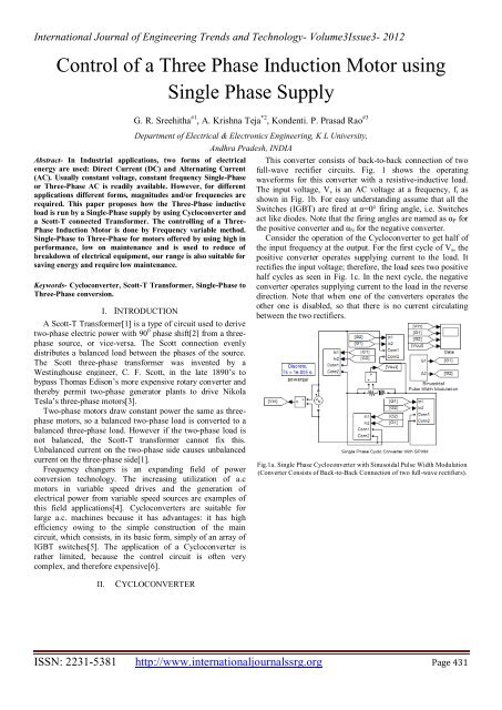
This converter consists <strong>of</strong> back-to-back connection <strong>of</strong> two<br />
full-wave rectifier circuits. Fig. 1 shows the operating<br />
waveforms for this converter with a resistive-inductive load.<br />
The input voltage, V s is an AC voltage at a frequency, f i as<br />
shown in Fig. 1b. For easy understanding assume that all the<br />
Switches (IGBT) are fired at α=0° firing angle, i.e. Switches<br />
act like diodes. Note that the firing angles are named as α P for<br />
the positive converter and α N for the negative converter.<br />
Consider the operation <strong>of</strong> the Cycloconverter to get half <strong>of</strong><br />
the input frequency at the output. For the first cycle <strong>of</strong> V s , the<br />
positive converter operates supplying current to the load. It<br />
rectifies the input voltage; therefore, the load sees two positive<br />
half cycles as seen in Fig. 1c. In the next cycle, the negative<br />
converter operates supplying current to the load in the reverse<br />
direction. Note that when one <strong>of</strong> the converters operates the<br />
other one is disabled, so that there is no current circulating<br />
between the two rectifiers.<br />
Fig.1a. <strong>Single</strong> <strong>Phase</strong> Cycloconverter with Sinusoidal Pulse Width Modulation<br />
(Converter Consists <strong>of</strong> Back-to-Back Connection <strong>of</strong> two full-wave rectifiers).<br />
II.<br />
CYCLOCONVERTER<br />
ISSN: 2231-5381 http://www.internationaljournalssrg.org Page 431
International Journal <strong>of</strong> Engineering Trends and Technology- Volume3Issue3- 2012<br />
Fig.2a. Positive Gate Pulse for Positive Conversion (for f/2).<br />
Fig.1b. Input Voltage to the Cycloconverter having f = 50 Hz Frequency.<br />
Fig.2b. Negative Gate Pulse for Negative Conversion (for f/2).<br />
Fig.2. <strong>Control</strong> Pulses for Cycloconverter (α=0° firing angle).<br />
Fig.1c. Output Voltage <strong>of</strong> the Cycloconverter having f/2 = 50/2 Hz Frequency<br />
Fig.1d. Output Voltage <strong>of</strong> Cycloconverter having f/4 = 50/4 Hz Frequency.<br />
Fig.1. <strong>Single</strong> <strong>Phase</strong> Cycloconverter with R-L load.<br />
To get one-fourth <strong>of</strong> the input frequency at the output, for<br />
the first two cycles <strong>of</strong> V s , the positive converter operates<br />
supplying current to the load. It rectifies the input voltage;<br />
therefore, the load sees 4 positive half cycles as seen in Fig.<br />
1d. In the next two cycles, the negative converter operates<br />
supplying current to the load in the reverse direction.<br />
ISSN: 2231-5381 http://www.internationaljournalssrg.org Page 432
International Journal <strong>of</strong> Engineering Trends and Technology- Volume3Issue3- 2012<br />
The frequency <strong>of</strong> the output voltage, V o in Fig. 1d. is 4<br />
times less than that <strong>of</strong> V s , the input voltage, i.e. f o /f i = 1/4.<br />
Thus, this is a step-down Cycloconverter. On the other hand,<br />
Cycloconverters that have f o /f i > 1 frequency relation are<br />
called step-up Cycloconverters. Note that step-down<br />
Cycloconverters are more widely used than the step-up ones.<br />
The frequency <strong>of</strong> V 0 can be changed by varying the number <strong>of</strong><br />
cycles the positive and the negative converters work. It can<br />
only change as integer multiples <strong>of</strong> f i in 1f-1f Cycloconverters.<br />
With the above operation, the 1f-1f Cycloconverter can only<br />
supply a certain voltage at a certain firing angle α. The dc<br />
output <strong>of</strong> each rectifier is:<br />
√<br />
----- (1)<br />
where V is the input rms voltage.<br />
Then the peak <strong>of</strong> the fundamental output voltage is<br />
√<br />
( )<br />
----- (2)<br />
Equation 2 implies that the fundamental output voltage<br />
depends on α. For α = 0°,<br />
where<br />
√<br />
. If α = (π/3)°, then . Thus varying ,<br />
the fundamental output voltage can be controlled. Constant <br />
operation gives a crude output waveform with rich harmonic<br />
content. With different 's, the less are the harmonics.<br />
III. SCOTT – T TRANSFORMER<br />
Assuming the desired voltage is the same on the two and<br />
three phase sides, the Scott-T transformer connection consists<br />
<strong>of</strong> a centre-tapped 1:1 ratio main transformer, T1, and an<br />
86.6% (0.5√3) ratio teaser transformer, T2. The centre-tapped<br />
side <strong>of</strong> T1 is connected between two <strong>of</strong> the phases on the<br />
three-phase side. Its centre tap then connects to one end <strong>of</strong> the<br />
lower turn count side <strong>of</strong> T2, the other end connects to the<br />
remaining phase. The other side <strong>of</strong> the transformers then<br />
connect directly to the two pairs <strong>of</strong> a two-phase four-wire<br />
system.<br />
Fig.3. Scott-T Transformer (2ø to 3ø).<br />
Fig.4. Shows the characteristics <strong>of</strong> a <strong>Three</strong> <strong>Phase</strong> <strong>Induction</strong><br />
<strong>Motor</strong> with the input voltage 220V and frequency 50Hz. The<br />
main transformer <strong>of</strong> a Scott-T having 220∟0 0 and teaser<br />
transformer having 220∟90 0 . Fig.4a. shows one <strong>of</strong> the three<br />
phase voltages at output <strong>of</strong> the Scott-T transformer. Here input<br />
is always equal to output voltage magnitude, because the<br />
transformer ratio is 1:1.<br />
Fig.4a. Scott-T Transformer Circuit in MATLAB – Simulink.<br />
ISSN: 2231-5381 http://www.internationaljournalssrg.org Page 433
International Journal <strong>of</strong> Engineering Trends and Technology- Volume3Issue3- 2012<br />
Fig.4b. One <strong>of</strong> <strong>Three</strong> <strong>Phase</strong> voltage Waveform (Output <strong>of</strong> Scott-T Transformer).<br />
Fig.4c. Electromagnetic Torque waveform with 220V/50Hz <strong>Single</strong> <strong>Phase</strong> supply.<br />
Fig.4d. Rotor Speed waveform with 220V/50Hz <strong>Single</strong> Input supply.<br />
Fig.4e. Stator <strong>Three</strong> <strong>Phase</strong> Current waveform with 220V/50Hz <strong>Single</strong> <strong>Phase</strong> supply.<br />
Fig.4. Performance <strong>of</strong> <strong>Three</strong> <strong>Phase</strong> <strong>Induction</strong> <strong>Motor</strong> with 220V/50Hz <strong>Single</strong> <strong>Phase</strong> Input supply.<br />
ISSN: 2231-5381 http://www.internationaljournalssrg.org Page 434
International Journal <strong>of</strong> Engineering Trends and Technology- Volume3Issue3- 2012<br />
IV. 1-ø TO 3-ø CONVERSION WITH<br />
CYCLOCONVERTER & SCOTT-T TRANSFORMER<br />
This paper proposed a circuit for industries to run three<br />
phase induction loads with single-phase supply. This is done<br />
by MATLAB Simulink.<br />
At very first, single-phase supply converted to two-phase<br />
supply through two single-phase Cycloconverters. In these<br />
two Cycloconverters, one is directly converted single-phase to<br />
single-phase with 0 0 Delay. Second one is converted singlephase<br />
to single-phase with 90 0 Delay. These two supplies<br />
called as two-phase supply. This two-phase supply directly<br />
fed to the Scott-T transformer. Here this transformer converts<br />
two-phase to three-phase to drive the three-phase induction<br />
load.<br />
In the second section the Cycloconverter operation<br />
explained with sinusoidal pulse width modulation technique<br />
(SPWM). But in this section Cycloconverter operated with<br />
manual pulse generator. Because, the output <strong>of</strong> a<br />
Cycloconverter having more dc component by <strong>using</strong> SPWM<br />
technique. To mitigate the dc component with LC-filter. We<br />
are not got the filter values exactly.<br />
Fig.5a. Cycloconverter & Scott-T Transformer Circuit to drive <strong>Three</strong>-<strong>Phase</strong> Inductive Loads in MATLAB – Simulink.<br />
Fig.5b. Electromagnetic Torque waveform.<br />
ISSN: 2231-5381 http://www.internationaljournalssrg.org Page 435
International Journal <strong>of</strong> Engineering Trends and Technology- Volume3Issue3- 2012<br />
Fig.5c. Rotor Speed waveform.<br />
Fig.5d. Stator <strong>Three</strong> <strong>Phase</strong> Current waveform.<br />
Fig.5. Performance <strong>of</strong> <strong>Three</strong> <strong>Phase</strong> <strong>Induction</strong> <strong>Motor</strong> (i.e., With Two <strong>Single</strong>-<strong>Phase</strong> Cycloconverters & one Scott-T Transformer).<br />
Fig.5. Shows the characteristics <strong>of</strong> a <strong>Three</strong> <strong>Phase</strong> <strong>Induction</strong><br />
<strong>Motor</strong> with the input voltage 220V and frequency 50Hz. The<br />
main transformer <strong>of</strong> a Scott-T having 440∟0 0 and teaser<br />
transformer having 440∟90 0 as input voltage. These two<br />
voltages got by the two single-phase Cycloconverters. Fig.5b.<br />
shows the Electromagnetic magnetic torque. Fig.5c. shows the<br />
rotor speed. Fig.5d. shows the three-phase stator current. Here<br />
input is always equal to output voltage magnitude <strong>of</strong> the Scott-<br />
T transformer, because the transformer ratio is 1:1.<br />
The main advantage <strong>of</strong> this is, to get variable speed by<br />
varying the frequency at the input side. This is type <strong>of</strong><br />
mechanism is very easy and simple compare to other control<br />
techniques (i.e., controlling <strong>of</strong> three-phase supply directly).<br />
V. CONCLUSION<br />
This paper proposes a new topology for controlling a threephase<br />
induction motor with single-phase supply. Here to<br />
control <strong>of</strong> Cycloconverter by the firing pulses. With the help<br />
<strong>of</strong> variable frequencies got the variable speeds <strong>of</strong> a threephase<br />
induction motor. The major role <strong>of</strong> a Scott-T<br />
transformer is used to convert two-phase, output <strong>of</strong> two<br />
Cycloconverters to three-phase.<br />
ACKNOWLEDGMENT<br />
It is our sincere obligation to thank our well-wishers Dr. M.<br />
Venu GopalaRao,Ph.D. EEE HOD, Mr. D. Seshi Reddy,M.Tech.<br />
(Ph.D.), Associate Pr<strong>of</strong>essor & Mrs. S.V.N.L. Lalitha,M.Tech.<br />
(Ph.D.), Associate Pr<strong>of</strong>essor in KL University at Vaddeswaram,<br />
Guntur Dist.<br />
REFERENCES<br />
[1] Mazin, Hooman Erfanian; Gallant, Joey (August 14, 2009, 2010). "A<br />
Probabilistic Analysis on the Harmonic Cancellation Characteristics <strong>of</strong><br />
the Scott Transformer". J. Electromagnetic Analysis & Applications 2:<br />
18–24. Retrieved 20 December 2011.<br />
[2] Distribution Transformer Manual, GET-2485T. Hickory, NC: General<br />
Electric Company. 1996. pp. 64.<br />
[3] Harold C. Passer, The Electrical Manufacturers, 1875-1900, Harvard,<br />
1953, p. 315.<br />
[4] Rezgar Mohammed Khalil, Maamoon Al-Kababjie, ”Modeling and<br />
Simulation <strong>of</strong> multi-pulse Cycloconverter fed AC <strong>Induction</strong> motor and<br />
study <strong>of</strong> output power factor”, Al-Rafidain Engineering, vol.15, no.1,<br />
2007.<br />
[5] Miyazawa, S. Nakamura, F. and Yamada, N. “Effective Approximation<br />
Suitable for the <strong>Control</strong> Algorithm <strong>of</strong> Microprocessor Based<br />
Cycloconverter”, IEEE Transaction, August 1988.<br />
[6] Mohammed, B.A., “Microprocessor Based <strong>Control</strong> <strong>of</strong> Cycloconverters”,<br />
M.Sc. Thesis, University <strong>of</strong> Mosul, Iraq, December 1990.<br />
ISSN: 2231-5381 http://www.internationaljournalssrg.org Page 436