3 WELL CONSTRUCTION 3.1 Strategy - Encana
3 WELL CONSTRUCTION 3.1 Strategy - Encana
3 WELL CONSTRUCTION 3.1 Strategy - Encana

Create successful ePaper yourself
Turn your PDF publications into a flip-book with our unique Google optimized e-Paper software.
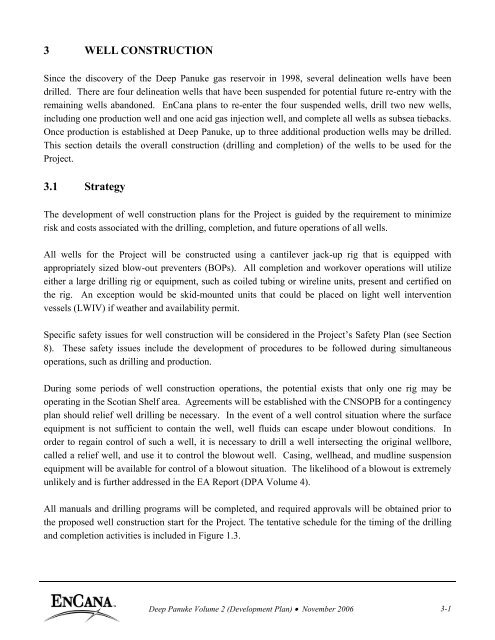
3 <strong>WELL</strong> <strong>CONSTRUCTION</strong><br />
Since the discovery of the Deep Panuke gas reservoir in 1998, several delineation wells have been<br />
drilled. There are four delineation wells that have been suspended for potential future re-entry with the<br />
remaining wells abandoned. EnCana plans to re-enter the four suspended wells, drill two new wells,<br />
including one production well and one acid gas injection well, and complete all wells as subsea tiebacks.<br />
Once production is established at Deep Panuke, up to three additional production wells may be drilled.<br />
This section details the overall construction (drilling and completion) of the wells to be used for the<br />
Project.<br />
<strong>3.1</strong> <strong>Strategy</strong><br />
The development of well construction plans for the Project is guided by the requirement to minimize<br />
risk and costs associated with the drilling, completion, and future operations of all wells.<br />
All wells for the Project will be constructed using a cantilever jack-up rig that is equipped with<br />
appropriately sized blow-out preventers (BOPs). All completion and workover operations will utilize<br />
either a large drilling rig or equipment, such as coiled tubing or wireline units, present and certified on<br />
the rig. An exception would be skid-mounted units that could be placed on light well intervention<br />
vessels (LWIV) if weather and availability permit.<br />
Specific safety issues for well construction will be considered in the Project’s Safety Plan (see Section<br />
8). These safety issues include the development of procedures to be followed during simultaneous<br />
operations, such as drilling and production.<br />
During some periods of well construction operations, the potential exists that only one rig may be<br />
operating in the Scotian Shelf area. Agreements will be established with the CNSOPB for a contingency<br />
plan should relief well drilling be necessary. In the event of a well control situation where the surface<br />
equipment is not sufficient to contain the well, well fluids can escape under blowout conditions. In<br />
order to regain control of such a well, it is necessary to drill a well intersecting the original wellbore,<br />
called a relief well, and use it to control the blowout well. Casing, wellhead, and mudline suspension<br />
equipment will be available for control of a blowout situation. The likelihood of a blowout is extremely<br />
unlikely and is further addressed in the EA Report (DPA Volume 4).<br />
All manuals and drilling programs will be completed, and required approvals will be obtained prior to<br />
the proposed well construction start for the Project. The tentative schedule for the timing of the drilling<br />
and completion activities is included in Figure 1.3.<br />
Deep Panuke Volume 2 (Development Plan) · November 2006 3-1
3.2 Exploration and Delineation Wells<br />
The Deep Panuke gas reservoir was discovered in late 1998, with the original discovery well, PP-3C,<br />
drilled from the Panuke platform using the jack-up/drilling production unit, Rowan Gorilla III (RGIII).<br />
This well discovered a highly fractured, highly porous carbonate formation, which led to significant loss<br />
circulation problems during drilling. The discovery well was eventually cased, tested and then<br />
abandoned. Following this discovery, a delineation well and its sidetrack, PI-1A/B, were drilled from<br />
the Panuke platform in late 1999. The sidetrack, PI–1B, was tested in early 2000 and then suspended for<br />
potential re-use. Since that time, the PI-1B well has been abandoned with the exception of cutting the<br />
conductor below the mudline. Because PI-1B was drilled from the Panuke Platform, a mudline<br />
suspension system was not used, making it very difficult to convert to a subsea wellhead. The decision<br />
was made to abandon PI-1B due to the risk and technical challenges related to converting it to a subsea<br />
wellhead.<br />
In May 2000, the RGIII moved to a new location and drilled the third delineation well, H-08. This<br />
vertical well found a substantial pay zone of gas and also experienced significant loss circulation<br />
problems; the well was tested and suspended. Concurrently, the Rowan Gorilla V (RGV) moved to drill<br />
M-79; this was the deepest vertical well through the Abenaki reef to date. The M-79 vertical well<br />
encountered poor porosity; the main well was plugged back and a sidetrack was initiated by milling a<br />
window near the bottom of the 245 mm casing. The sidetrack was drilled to almost horizontal, and it<br />
was cased, tested, and then suspended.<br />
After finishing the H-08 well, the RGIII was moved to drill the Panuke F-09 well targeting prospects to<br />
the west of Deep Panuke on the back reef. The F-09 well was drilled directionally to investigate targets<br />
from the Abenaki 6 to the Scatarie formation. Intermediate logging proved the Abenaki 3 & 4 were<br />
water-saturated and so drilling was terminated at 373<strong>3.1</strong> m true vertical depth (TVD). A drill stem test<br />
(DST) was conducted in the Abenaki 5 but proved non-commercial. The well was plugged and<br />
abandoned.<br />
In July 2001, the RGV was again mobilized to drill Musquodoboit E-23 to the south west of the Panuke<br />
license on EL 2360. It penetrated 466 m of Jurassic limestones and lesser amounts of sandstone and<br />
shale. The prospective Abenaki 5 zone did not reveal any gas bearing intervals. Zones of vuggy<br />
porosity were found to contain water from the electric logging evaluation. The well was subsequently<br />
plugged and abandoned.<br />
In May 2003, further delineation drilling was conducted using the RGV, to first drill Margaree F-70 on EL<br />
2387 and then MarCoh D-41 on SDL 2255H. Both wells were drilled vertically at locations to the northeast<br />
of the discovery well. Each well encountered a substantial gas pay zone in the Abenaki. A production<br />
Deep Panuke Volume 2 (Development Plan) · November 2006 3-2
test was conducted on Margaree F-70 and the well was subsequently suspended. An extensive logging<br />
program was conducted on MarCoh D-41 including MDT pressure points and fluid sampling in lieu of a<br />
production test. The D-41 well was cased and suspended.<br />
In November 2005, the Rowan Gorilla VI (RGVI) was mobilized to further delineate the Deep Panuke field<br />
to the northeast by drilling the Dominion J-14 well. The vertical well was drilled to a total depth of 3700 m<br />
TVD but did not encounter any gas bearing formations. The Dominion J-14A horizontal sidetrack was<br />
drilled due south from the J-14 well but did not encounter any gas bearing formations. Both the vertical<br />
well and sidetrack were abandoned.<br />
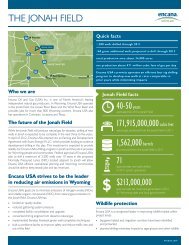
Figure <strong>3.1</strong> shows the relative locations of the existing wells. Table <strong>3.1</strong> lists details of the existing wells.<br />
The Project plans to re-enter and complete the Panuke H-08, M-79A, Margaree F-70 and MarCoh D-41<br />
wells as part of the pool development.<br />
Figure <strong>3.1</strong><br />
Deep Panuke Exploration and Delineation Wells<br />
Deep Panuke Volume 2 (Development Plan) · November 2006 3-3
Table <strong>3.1</strong><br />
Exploration and Delineation Wells - Summary Information<br />
Well Name Year Drilled Status Rig Measured Depth 1 TVD 2<br />
PP-3C (Discovery Well) 1998 Abandoned RGIII 4163 m 3643 m<br />
Panuke PI-1A 1999 Abandoned RGIII 4033 m 3595 m<br />
Panuke PI-1B 2000 Abandoned 3 RGIII 4046 m 3589 m<br />
Panuke H-08 2000 Suspended RGIII 3682 m 3682 m<br />
Panuke M-79 2000 Abandoned RGV 4598 m 4597 m<br />
Panuke M-79A 2000 Suspended RGV 3934 m 3492 m<br />
Panuke F-09 2000 Abandoned RGIII 3815 m 3654 m<br />
Musquodoboit E-23 2001 Abandoned RGV 3818 m 3814 m<br />
Margaree F-70 2003 Suspended RGV 3677 m 3676 m<br />
MarCoh D-41 2003 Suspended RGV 3625 m 3625 m<br />
Dominion J-14 2005 Abandoned RGVI 3700 m 3699 m<br />
Dominion J-14A 2006 Abandoned RGVI 4440 m 3568 m<br />
1 Measured Depth below the Rotary Table (RT)<br />
2 True vertical depth (TVD) below the Rotary Table (RT)<br />
3 PI-1B has been abandoned downhole but still requires cutting and removal of conductor pipe 3m below the mudline.<br />
3.3 Development Drilling<br />
EnCana’s current plan is to re-enter the four suspended wells (H-08, M-79A, F-70, D-41), drill two new<br />
wells prior to start-up, including one production well and one acid gas injection well, and complete all<br />
wells as subsea tiebacks. Once production is established, up to three additional production wells may be<br />
drilled. All of these wells will be completed with subsea production trees and tied back to the MOPU<br />
with individual flowlines and control umbilicals.<br />
3.<strong>3.1</strong> Tentative Drilling Schedule<br />
The current schedule is to start well construction activities in early-to-mid 2009 to enable full production<br />
to be available by the time the MOPU and pipelines are commissioned in 2010. During this time, the<br />
four existing exploration wells will be re-entered and completed, and one new production well and one<br />
acid gas injection well will also be drilled and completed. This schedule may change based on<br />
availability of existing equipment and services. Figure 1.3 provides a preliminary overall well<br />
development schedule.<br />
3.3.2 Drilling Hazards<br />
Extensive drilling experience within the area of the Deep Panuke pool provides an excellent understanding<br />
of the well construction hazards. The two primary areas of concern when dealing with any wells in the<br />
Abenaki reef structure are the potential for loss circulation problems and the H 2 S content of Deep Panuke<br />
gas. While these operational difficulties were dealt with appropriately during the drilling of the discovery<br />
and delineation wells, they must be appropriately accounted for during any well construction activity.<br />
Deep Panuke Volume 2 (Development Plan) · November 2006 3-4
Other more routine drilling hazards could include hole instability, shallow gas and differential sticking.<br />
These hazards are described in more detail as follows.<br />
3.3.2.1 Loss Circulation<br />
While drilling into a highly fractured/highly porous carbonate formation, it is sometimes difficult to<br />
maintain circulation. Under normal drilling circumstances, the drilling fluid is pumped into the wellbore<br />
through the drillstring and out of the drill bit and back to surface through the annulus. From the surface to<br />
the drill bit and back to surface represents one full circulation of drilling fluids. The volume of fluid<br />
entering the wellbore is equivalent to the volume of fluid coming back to surface under normal drilling<br />
conditions and any change in this would represent a well control situation. This condition was encountered<br />
during the drilling of the discovery well, PP-3C, where it was determined that the formation would only<br />
support a mud density of approximately 10 kg/m 3 more than the wellbore fluid ingress density required to<br />
keep formation fluids in place. Therefore, a wellbore that would stand full of drilling mud would begin to<br />
lose fluid as soon as circulation began due to annular pressure loss.<br />
To overcome this problem, a drilling method called the annular velocity control (AVC) drilling technique<br />
was developed. The AVC technique employs a rotating BOP while injecting seawater down the drill string<br />
and casing annulus at a rate that is higher than the gas migration rate up the wellbore to maintain dynamic<br />
well control while drilling. Initially, the AVC technique involved the use of stripping and snubbing<br />
equipment to move the drill string (or casing) into and out of the wellbore. A modification to this procedure<br />
replaces the stripping and snubbing equipment with continuously pumping a weighted brine solution while<br />
moving the drill string (or casing) in and/or out of the wellbore.<br />
3.3.2.2 Hydrogen Sulphide (H 2 S)<br />
H 2 S was encountered during all well tests from the discovery and delineation wells, but none was detected<br />
during the drilling of any of these wells. Through proper drilling practices and the application of<br />
appropriate environment, health and safety (EHS) procedures and policies, the exposure of well<br />
construction operations to the H 2 S risk will be managed safely.<br />
3.3.2.3 Shallow Gas<br />
A shallow gas deposit could cause uncontrollable well flow before adequate casing is set to allow use of<br />
a BOP system to divert the gas flow. Although some site surveys have indicated the possibility of<br />
shallow gas on the Panuke license, it has not been encountered in any of the wells drilled to date.<br />
Detailed site surveys of the proposed new well drilling locations will be performed to ensure shallow gas<br />
is not a risk during drilling operations.<br />
Deep Panuke Volume 2 (Development Plan) · November 2006 3-5
3.3.2.4 Hole Instability<br />
Hole instability problems result in extended drilling times and increased costs but do not pose a hazard<br />
to personnel or the environment. The Deep Panuke exploration wells were drilled using a water-based<br />
drilling fluid which provided good hole stability and inhibition to reactive shale sections when fluid<br />
density is properly controlled. This water-based fluid also provided excellent directional control while<br />
drilling carbonate section in highly deviated, near horizontal, sidetracks such as Panuke M-79A and<br />
Dominion J-14A.<br />
The new drill production and injection wells are expected to be vertical or sidetracked similar to M-79A<br />
or J-14A. A water-based mud system will be used for all new wells with careful attention to the density<br />
and visco-elastic properties of the fluid in order to prevent any hole stability problems.<br />
3.3.2.5 Abnormal Pressure<br />
Abnormal pressures are not expected throughout the Abenaki Reef. Reservoir pressure in the Abenaki 5<br />
is approximately 36.3 MPa at 3309 m TVD. This pressure has been measured directly using logging<br />
tools and through well testing and has been correlated with all of the Deep Panuke delineation wells.<br />
3.3.2.6 Well Control<br />
As described above in Section 3.3.2.1, well control is of primary concern due to the very tight pore<br />
pressure kick tolerances within the reservoir. The discovery well, PP-3C, experienced significant loss<br />
circulation that was eventually controlled using a seawater bullheading technique. The probability of<br />
well control incidents or uncontrolled kicks is low through the utilization of EnCana’s tripping (moving<br />
pipe in or out of the wellbore), drilling, and AVC techniques.<br />
3.3.2.7 Differential Sticking<br />
Differential sticking across the hydrocarbon zones is possible due to lost circulation and AVC drilling.<br />
Tight control of drilling fluid properties and good operating practices will minimize this potential.<br />
3.3.2.8 Directional Control<br />
Direction will be closely controlled using the latest measurement-while-drilling (MWD) technologies on the<br />
additional development wells. The wellbore trajectory will also be confirmed by the application of two<br />
independent measurement sources. Likewise, locating existing wells is not a concern due to accurate<br />
records and tight directional control techniques used during the previous drilling of these wells.<br />
Deep Panuke Volume 2 (Development Plan) · November 2006 3-6
3.3.3 Drilling Details<br />
This section presents the well design based on experience from existing Deep Panuke discovery and<br />
delineation wells. The well design will evolve over the life of the Project and the field to take advantage of<br />
equipment development, new techniques, and drilling experience. The detailed design specifications will<br />
be submitted with the Drilling Program prior to the “spud” of each well in accordance with CNSOPB<br />
Regulations. “Spudding” a well is generally considered the first moment the drill bit touches the seabed or<br />
ground level in the case of a land well.<br />
3.3.<strong>3.1</strong> Casing and Hole Sizes<br />
The normal drilling program for all Deep Panuke wells involves conventional hole and casing/pipe<br />
sizes. All casing designs are based on Nova Scotia Offshore Area Petroleum Drilling Regulations.<br />
Additional information on casing design and drilling program is contained in the Part Two (DPA-Part 2,<br />
Ref. # <strong>3.1</strong>)<br />
For the new production and injection wells drilled, the conductor pipe (first string of pipe) will be set<br />
approximately 100 m below the seafloor by first drilling a 914 mm hole and then cementing a 762 mm<br />
conductor pipe. This is the same method that has been used on the existing suspended delineation wells.<br />
This section will be drilled primarily with seawater and viscosifiers to aid in ensuring cuttings removal<br />
from the wellbore. These cuttings are deposited at the seabed and approximately equivalent to the<br />
volume of the hole drilled.<br />
The conductor pipes will serve as the primary weather barrier to take environmental loading and protect<br />
the inner strings of casing (length of pipe) while drilling the well. The conductors also take the surface<br />
loading implied by the other strings of casing that are returned to the mudline suspension system. Once<br />
the drilling has been completed, the conductors will be removed and the well will be converted to a<br />
subsea wellhead. With the production tree installed, a high pressure riser will be required to tieback to<br />
the surface BOP stack. The high pressure riser will be designed to withstand the environmental loads as<br />
well as all internal design loads.<br />
All production and injection wells will set the surface casing into the Wyandot member (refer to Figure<br />
2.5) at approximately 950 m true vertical depth from sea surface (TVDss) in the general direction that<br />
the bottom of the well will be located. The existing suspended delineation wells have drilled a 445 mm<br />
hole and set 340 mm surface casing approximately 50 m into the Wyandot with cement back to the<br />
seabed. The BOP stack is then installed on top of the surface casing prior to drilling the intermediate<br />
hole section.<br />
Deep Panuke Volume 2 (Development Plan) · November 2006 3-7
Figure 3.2<br />
Typical Production Well Schematic<br />
Deep Panuke Volume 2 (Development Plan) · November 2006 3-8
For the re-activation wells, a 311 mm intermediate hole section has been drilled just into the top of the<br />
limestone at approximately 3200 m TVDss. A 244.5 mm intermediate casing string has been set 20m<br />
into the Abenaki 7/6 formation and cemented back just above any potential hydrocarbon bearing sands<br />
(~2300m).<br />
A rotating BOP and an injection spool will be installed with the surface BOP stack in preparation for<br />
AVC drilling techniques and the main hole section will be drilled through the productive interval of the<br />
carbonate reef. For the re-entry wells, the reservoir section has been drilled to a total depth of circa<br />
3650m TVDss which is about 150m past the gas/water contact (GWC) at 3504m TVDss. On many of<br />
the delineation wells, this GWC was not clearly evident while drilling the section as the formation was<br />
not porous at this depth; however, it was clearly identified while drilling the MarCoh D-41 well. On<br />
each of the wells to be re-used for production, a 177.8 mm liner (string of pipe) has been installed across<br />
the reservoir section and cemented back to the previous casing shoe.<br />
The new production well(s) will be similarly constructed to the existing suspended delineation wells.<br />
Prior to drilling the reservoir section and with the well secured, the surface wellhead and conductor will<br />
be removed and the well will be converted to a subsea wellhead. The production tree will be installed<br />
with the high pressure riser connected back to the surface BOP stack. For the new producing well(s),<br />
the reservoir section may be left open, with no liner in place, in order to maximize the flow potential of<br />
the well.<br />
For re-entry of the existing wells, a 762 mm “trash cap” will first be removed from the conductor stub<br />
3m above the seafloor. A “trash cap” is a cylindrical device closed on one end that fits over the<br />
conductor to keep out sea life or falling debris. Once the trash cap has been removed, a running and<br />
retrieving tool is used to back off the temporary abandonment caps from the 340 mm and then 244.5 mm<br />
mudline suspension thread profiles. Each of the wells then has a 100m thick cement plug set at<br />
approximately 2900 m in the 244.5 mm casing that has to be drilled out.<br />
For H-08, there are two mechanical bridge plugs set below the cement plug that must also be retrieved<br />
prior to gaining access to the 177.8 mm liner section. For M-79A, there is one mechanical bridge plug<br />
set inside the 244.5 mm casing and one inside the 177.8 mm liner that will be pulled. Also, each of<br />
these two wells has a production packer and 114.3 mm tailpipe installed with plug and prong profile<br />
nipples installed. The tailpipes have two plugs and prongs that must be pulled before opening the well<br />
to flow. Pulling the plugs and prongs will be done only after the new completion has been installed and<br />
the well is ready for production clean-up operations. The Margaree F-70 well has a 100 m cement plug<br />
set just below the 177.8 mm liner top which will be drilled out. Margaree F-70 and MarCoh D-41 each<br />
have a sealed permanent packer installed in the 177.8 mm liner that will either be drilled out or cut and<br />
pulled. For F-70, once the packer is pulled, the well is open to the perforations below that were put in<br />
the liner during production testing. On MarCoh D-41, the well was not tested and therefore it should be<br />
Deep Panuke Volume 2 (Development Plan) · November 2006 3-9
secure after pulling the 177.8 mm packer. Due to size restrictions on the subsurface safety valve, the<br />
abandonment packer will have to be pulled prior to running the completions on these two wells.<br />
The production wells will all be completed with a downhole packer (plus other ancillary downhole<br />
equipment), production tubing, surface controlled subsurface safety valve, a tubing hanger, and a subsea<br />
production tree. Once all hydrostatic tests and function tests are performed, the production wells will be<br />
opened for clean-up flow on the drilling rig. This will remove any water or debris from the wellbore<br />
prior to handover for production operations on the MOPU. See Figure 3.2 for details on the production<br />
wells.<br />
The injection well will be drilled using similar processes and procedures as with the production wells.<br />
Once the surface casing is set in the Wyandot formation, the main well bore will be drilled vertically to<br />
the injection zone in the Upper Mississauga formation located at approximately 2400m TVDss. See<br />
Figure 3.3 for details on the injection well. Similar to the production well, the completion for the<br />
injection well will consist of tubing, downhole packer, subsurface safety valve, tubing hanger and<br />
injection tree.<br />
This injection well for acid gas and condensate (if necessary) will be drilled into a porous and permeable<br />
zone in the Upper Mississauga Formation; the targeted injection zone is the Tidal-Fluvial Sandstone.<br />
The impermeable Naskapi shales located directly above the Upper Mississauga Formation will prevent<br />
any migration of injected acid gas or condensate. The Upper Mississauga Formation will be capable of<br />
containing the entire acid gas and surplus condensate volumes that will be produced over the life of the<br />
Project. Migration of injection fluids to other formations and/or to the surface is considered extremely<br />
unlikely. The possibility of acid gas injection souring the Panuke oil zone is also considered to be<br />
extremely unlikely. The injection zone in the Upper Mississauga is expected to have 14% porosity and<br />
400 mD permeability.<br />
3.3.3.2 Drilling Fluid Program<br />
Water-based muds (WBM) will be used in development drilling. These muds are used to protect and<br />
clean the drill hole, for overbalancing formation pressures, and for bringing cuttings to the surface. The<br />
selection of the drilling fluid is based on factors such as the hole angle, the formation types drilled<br />
(mudstone, sandstone, clays, etc.), and the time of exposure.<br />
WBM is a suspension of solids and dissolved material in a carrier base fluid of water. WBM tends to be<br />
used for wells that are normally pressured or do not encounter difficult geology. Based on the<br />
experience gained while drilling the Deep Panuke delineation wells, it was determined that only WBM<br />
will be used for any new development drilling activities. This fluid has proven to be successful even<br />
when drilling highly deviated wellbores such as the M-79A sidetrack.<br />
Deep Panuke Volume 2 (Development Plan) · November 2006 3-10
Figure 3.3<br />
Typical Injection Well Schematic<br />
Deep Panuke Volume 2 (Development Plan) · November 2006 3-11
For each well there are three hole sections below the 762 mm conductor, each of which has different<br />
mud-type requirements. These three sections are: (1) surface hole section (from seabed, ± 100m below<br />
the sea floor (BSF), to the Wyandot formation, ± 950m TVD); (2) intermediate hole section (from the<br />
Wyandot formation to the top of Abenaki formation at ± 3200m TVD); and (3) the main hole section<br />
(from the top of the Abenaki formation to the production zone, ± 3400 m TVD).<br />
WBM will be used to drill the surface hole for several reasons. The surface hole section drills very<br />
quickly, so oil-based mud would not increase the rate of penetration. Most importantly, the potential for<br />
surface (seafloor) break-through of the drilling fluid while drilling this hole section is fairly significant.<br />
From an environmental and economic perspective, this break-through would be undesirable if oil-based<br />
muds were used. The WBM for this hole section will be a one to one ratio of pre-hydrated bentonite<br />
(gel) to seawater.<br />
For the intermediate section, WBM will be used. The drilling fluid for the intermediate hole will be<br />
selected based primarily on pressure regime, formation types drilled, and time of exposure. The<br />
selection of drilling fluid will be as per the delineation wells, which consisted of a 3% glycol and 8%<br />
potassium-chloride (KCl) mixture, which provides adequate shale inhibition, good lubricity for the drill<br />
bit and relatively good gauge hole.<br />
Finally, for the main hole section, WBM will also be used in case AVC drilling with total mud losses is<br />
required. This will be the same drilling fluid from the intermediate section; however, the glycol and<br />
KCl properties will not be maintained in the event total loss circulation is encountered. In the event total<br />
losses are encountered, the AVC drilling technique, which uses seawater, will be used to complete<br />
drilling the section. When moving the drill pipe in or out of the hole under AVC conditions, a densified<br />
brine (NaCl) mixture will be used throughout the length of the trip. Once the drill string is out of the<br />
hole, the well can again be controlled by pumping seawater at a continuous rate.<br />
For the wells to be re-entered and completed, some drilling is required to remove cement plugs. This<br />
will be done using a viscosified brine solution and therefore drilling mud will not be required. For<br />
running the completions, a completion fluid will be required which is described in more detail in section<br />
3.4.6.<br />
During drilling, the mud is circulated down the drillpipe from the drilling unit to the bottom of the<br />
wellbore and returned to the drilling unit in the annular space (between drill pipe and open hole/casing)<br />
carrying the cuttings from the well. Each hole section of a wellbore requires different fluid properties<br />
for the mud. Thus after each hole section, the mud is modified or changed out. WBM that is no longer<br />
required will be disposed of overboard, along with WBM cuttings in accordance with the Offshore<br />
Waste Treatment Guidelines (NEB et al. 2002).<br />
Deep Panuke Volume 2 (Development Plan) · November 2006 3-12
Through the life of the field, workovers will be required in the wellbores. These workovers will require<br />
various pieces of equipment to be sent offshore to perform downhole work. Completions brines may be<br />
used during these processes. These brines would be composed of water and a salt formulation kept in<br />
suspension using a viscosifier (polymer).<br />
3.3.3.3 Cementing Program<br />
The cementing program is expected to be similar to that used for the exploratory and delineation wells. The<br />
conductor will be cemented from shoe to seabed. The surface, intermediate and production casing will be<br />
cemented high enough to prevent future casing instability and to isolate permeable zones. To ensure a leakoff<br />
path for trapped-fluid expansion during production, intermediate and production casings may not be<br />
cemented into the previous casing shoe. If a liner is used in the new drill production wells, it will likely be<br />
left as an uncemented completion. External casing packers and stage tools may be used in high loss<br />
circulation situations to isolate the highly porous zones. If the liner is not cemented in place, proper<br />
metallurgy and liner top packers will ensure containment of the reservoir fluids to ensure a safe production<br />
wellbore. See Part Two for existing well casing and cementing details (DPA-Part 2, Ref. # 3.2).<br />
3.3.3.4 Well Control System<br />
The selection of the BOP configuration will be part of the rig evaluation process. Typically, a 346 mm, 103<br />
MPa (or 69 MPa) BOP equipped with four rams and an annular preventer will be installed on a 508 mm<br />
wellhead and used for the remainder of the well. In addition, an injection spool and rotational BOP will be<br />
installed for the sections drilled using the AVC method.<br />
3.3.4 Directional Drilling<br />
High hole angles (up to horizontal) may be used in the pay zone if increased productivity can be realized.<br />
Kick-off elevation and well profiles will be customized for each new well. High hole angles may also be<br />
used to minimize the possibility of encountering low quality reservoir rock since longer intervals of the<br />
reservoir will be exposed.<br />
Mud pulse telemetry directional tools will be used for directional control. The survey intervals and the<br />
type of surveying system used will be sufficient to assure entry into the target, while avoiding collision<br />
with adjacent wells, and providing adequate wellbore positioning information to reliably target a relief<br />
well. The wellbore trajectory will be confirmed by using two independent sources of MWD tools and<br />
correlating the data from each tool.<br />
Deep Panuke Volume 2 (Development Plan) · November 2006 3-13
3.4 Well Completions<br />
3.4.1 Design Philosophy<br />
For the Project, EnCana will use completion systems that are simple and reliable and meet all<br />
requirements for the corrosive environment in which they will be placed. The completions will be<br />
designed with minimal need for intervention as one of the key drivers. Preliminary design indicates that<br />
a 177.8 mm tubing string will be required for the production wells. The injection well will likely use a<br />
88.9 mm string. Due to size limitations with the existing delineation well construction, a smaller<br />
diameter subsurface safety valve will be required if a 177.8 mm tubing string is used. Figures 3.2 and<br />
3.3 provide schematic examples of the production well and injection well.<br />
Some of the production and injection objectives considered in the completion design are as follows:<br />
· to ensure operational safety;<br />
· to keep completions as simple as possible;<br />
· to minimize the number of wells while maximizing recovery and effectively depleting the reserves;<br />
· to ensure that downtime is minimized, including workovers;<br />
· to maintain a surplus in deliverability to mitigate production downtime due to workovers or<br />
suspended wells;<br />
· to maintain the plateau production of the Project as long as possible; and<br />
· to reduce or eliminate one-off well designs to reduce the number of spares required.<br />
The completions will ensure operational safety by providing an effective barrier and seal to the reservoir<br />
while at the same time providing a conduit for delivering well fluids to the subsea flowline. The design<br />
incorporates a surface controlled sub-surface safety valve (SSSV) that can effectively isolate the flow<br />
stream downhole in the event of an emergency or extended shut-down period. The tubing string,<br />
downhole completion equipment, and subsea production tree will be selected with materials suitable to<br />
the corrosive environment of well fluids over the life of the Project. The completions will be kept as<br />
simple as possible to reduce the potential of downhole equipment failures that could require a workover<br />
during the life of the Project.<br />
A rigorous engineering analysis will be performed to select the optimum tubing size, which will<br />
minimize the number of wells required to produce the field while at the same time maximize plateau<br />
production rates. This analysis will include liquid loading issues that might develop near the end of the<br />
Project’s economic life. Liquid loading occurs when the velocity of the flow stream is not sufficient to<br />
carry the liquid out of the wellbore. If the liquid builds up to significant levels, it would render the well<br />
insufficient to flow gas to surface. The velocity of the flow stream can be greatly affected by the size of<br />
Deep Panuke Volume 2 (Development Plan) · November 2006 3-14
the tubing string used. Generally, a smaller tubing string will yield higher flow velocities for the same<br />
wellhead pressure.<br />
The tubing may be sized such that peak production can be achieved from as little as three to four wells,<br />
which will allow some redundancy in the system. In the event of losing a well prematurely, some time<br />
would be required to mobilize a drilling rig before a workover could be completed. Redundancy in the<br />
production capacity of the wells would ensure peak or maximum production rates until the workover<br />
was completed.<br />
3.4.2 Tubing Design<br />
The tubing size will be maximized so that wellbore deliverability is not minimized by tubing constraints.<br />
Tubing size is limited by the outside diameter of the SSSV that will fit in the production casing. The<br />
tubing design must provide a flow conduit consistent with the inflow performance of the completed<br />
reservoir for the life of the field. The injection well will also be designed so that the tubing string does<br />
not provide pressure constraints.<br />
A monobore completion technique is an alternative to conventional completions. This style has production<br />
casing set near the top of the zone and uses a liner with a tie back packer to case the zone. Tubulars,<br />
downhole equipment, and trees are sized so that all equipment has a similar internal diameter. The Deep<br />
Panuke production wells will be “quasi-monobore” completions in that the subsurface safety valve will<br />
have a smaller inside diameter if a 177.8 mm tubing string is used due to the size constraints inside the<br />
244.5 mm casing.<br />
The design of the tubing connections will likely incorporate the following:<br />
· primary metal-to-metal seals;<br />
· multiple seals;<br />
· internal flush bore to prevent turbulence and corrosion;<br />
· high strength to withstand combined stresses;<br />
· minimum outside diameter; and<br />
· proven reliability with make-up/break-out history, particularly with respect to the design metallurgy.<br />
Where practical, one size, weight, grade, and connection will be used for each tubing string. This will<br />
minimize inventory and prevent the use of improper materials. Design limits for production tubing will<br />
meet or exceed the minimum tolerances of burst, tension and collapse, as calculated for the influence of<br />
combined stress under expected operating conditions. Final selection of the tubular connection will<br />
adhere to a connection qualification program that meets industry standards. The design will also<br />
Deep Panuke Volume 2 (Development Plan) · November 2006 3-15
incorporate any reduction in strength of materials due to temperature considerations under flowing and<br />
static well conditions.<br />
3.4.3 Metallurgy<br />
Careful consideration will be given to the materials used for tubulars, wellhead and downhole equipment<br />
because of exposure to corrosive fluids. Due to the presence of H 2 S, CO 2 , and chlorides, high alloy steel<br />
or corrosion resistant alloy (CRA) material may be required for tubulars and downhole equipment, and a<br />
corrosion resistant cladding may be required for subsea production tree equipment. Both production and<br />
injection wells will require detailed attention to the type of materials used for all components. EnCana<br />
has undertaken a study to determine the corrosion potential of the producing environment, and to<br />
determine suitable material and operational guidelines.<br />
3.4.4 Downhole Equipment<br />
The use of downhole completion tools will be minimized to reduce workover potential and wellbore<br />
complexity. The corrosive environment may reduce the performance of any equipment in the wellbore.<br />
The current design has tubing-retrievable SSSVs installed and all wells are equipped with a polished<br />
bore receptacle system to facilitate tubing change-out. The liner hanger design incorporates a packer<br />
assembly above the slips to ensure positive pressure integrity. The selection of all seals and elastomers<br />
will incorporate the results of the corrosion study.<br />
The maximum anticipated wellhead pressure will be contained safely and effectively through the<br />
selection of appropriate wellhead and production/injection tree equipment. Full-bore access to the<br />
tubing will allow for well-kill operations and be integrated with an operating and emergency control and<br />
shutdown system. Operating control and the emergency shut-down (ESD) system will be achieved<br />
through an electro-hydraulic umbilical from the MOPU to the subsea production tree. There will be a<br />
similar control panel from the drilling rig during completion and workover operations. Due to the<br />
operating environment, the wellhead and tree will most likely be clad in a corrosion/erosion resistant<br />
material. The tubing hanger will be ported to allow capability to handle the downhole gauge cable,<br />
SSSV control lines, and chemical injection. Depending upon anticipated workover scenarios, the<br />
hydraulic valves in the production trees may be capable of cutting both wireline and coiled tubing.<br />
The present completion strategy allows for the integration and use of typical downhole equipment<br />
including flow control nipples and mandrels for real-time pressure and temperature read-out gauges.<br />
Deep Panuke Volume 2 (Development Plan) · November 2006 3-16
3.4.5 Completion, Workover & Packer Fluid<br />
Separate completion fluids will be used for the following three phases of completions operations:<br />
· cleaning out the well;<br />
· providing an annular packer fluid; and<br />
· perforating (when required) pre-flow.<br />
Well clean-out will follow the installation of the production liner. The fluid used to clean the wellbore will<br />
be water based. Viscous pills of polymer gelled fluid may be used at total depth to sweep the hole clean.<br />
Packer fluid will likely be saltwater based (brine), corrosion inhibited, and oxygen and hydrogen scavenged.<br />
The packer fluid will be weighted such that in the event of a tubing leak deep in the well, the fluid will<br />
overbalance the formation pressure and kill the well.<br />
Three alternatives are available for a perforating/pre-flow fluid: non-damaging brine, a nitrogen cushion or<br />
an oil-based fluid. The fluid of choice will depend upon the well and the final reservoir requirements. All<br />
of these fluids will be flowed back to the processing or testing system during startup or cleanup.<br />
3.4.6 Annular Barriers<br />
There will be two annular barriers between the formation and the seafloor. The first barrier is the packer in<br />
the well, separating the formation from the annulus. The second barrier is the tubing hanger and annular<br />
kill wing valve on the subsea tree.<br />
3.4.7 Production/Injection Trees<br />
The production and injection trees will be located on the seafloor and will consist of a standard<br />
horizontal configuration. The reactivation wells have all been drilled with a surface wellhead and<br />
mudline suspension system. These wells will be converted to subsea wellheads through the mudline<br />
suspension system to provide a platform to mount and seal the subsea production trees.<br />
The maximum expected pressure at surface is approximately 37 MPa for all wells due to pressure testing<br />
requirements on abandonment. Therefore, standard 34.5 MPa subsea tree equipment will be not be<br />
sufficient and it may be necessary to have 45 MPa equipment or more standard 69 MPa.<br />
During workovers, control of the wellhead equipment from the MOPU will be locked out to avoid<br />
accidental operation of equipment when the workover unit is connected to the wellhead.<br />
Deep Panuke Volume 2 (Development Plan) · November 2006 3-17
Valve function on the subsea trees will be controlled by an electro-hydraulic umbilical tied back to the<br />
MOPU during production and to the drilling rig during completion and workovers. This system will be<br />
integrated with the MOPU ESD system during production operations. The subsea tree design will also<br />
incorporate an interface for remotely operated vehicle (ROV) intervention in the unlikely event of a topside<br />
control system failure.<br />
3.4.8 Perforating<br />
Perforating the production casing or liner allows formation fluids to flow into the wellbore (or injected<br />
fluids to access the reservoir). If perforating is required, the three alternatives available for perforating are :<br />
· wireline-conveyed perforating;<br />
· tubing-conveyed perforating using coiled tubing or drillpipe; or<br />
· tubing-conveyed perforating on tail pipe below the packer.<br />
The appropriate method of perforating for each individual well will be chosen based on its merits for the<br />
particular operation.<br />
3.5 Well Interventions<br />
EnCana's well workover philosophy for the Project is to maximize resource recovery from the Deep<br />
Panuke reservoir on an economically viable basis. The viability of workovers will take into account the<br />
amount of resource likely to be recovered together with the availability, proximity, and cost of MODU<br />
required to complete the workover, either major or minor.<br />
3.5.1 Major Workovers<br />
Major workovers are those that require a mobile drilling unit to accomplish the required tasks. Few major<br />
workovers are anticipated through the life of the field due to the reservoir type, the completion style and the<br />
use of quality components throughout.<br />
Typical major intervention activities include:<br />
· replacing tubing;<br />
· replacing tubing-retrievable SSSVs and control lines;<br />
· drilling up/replacing packer;<br />
· sidetracking to improve reservoir productivity; and<br />
Deep Panuke Volume 2 (Development Plan) · November 2006 3-18
· replacing a subsea production tree or valve.<br />
3.5.2 Minor Workovers<br />
Minor workovers could encompass both wireline and coiled tubing operations for both production and<br />
injection wells. Coiled tubing or wireline intervention could also require a jack-up rig or specialized light<br />
well intervention vessels, equipment and operating procedures.<br />
Typical minor workover activities include:<br />
· installing or removing plugs and prongs;<br />
· running or retrieving downhole pressure recorders;<br />
· production logging;<br />
· formation logging;<br />
· perforating;<br />
· circulating fill or debris from wellbore;<br />
· jetting scale or paraffin from tubing interior;<br />
· acid stimulations;<br />
· setting packers or bridge plugs; and<br />
· cement squeezes.<br />
Deep Panuke Volume 2 (Development Plan) · November 2006 3-19