Deep Panuke Project Description - Encana
Deep Panuke Project Description - Encana
Deep Panuke Project Description - Encana

You also want an ePaper? Increase the reach of your titles
YUMPU automatically turns print PDFs into web optimized ePapers that Google loves.
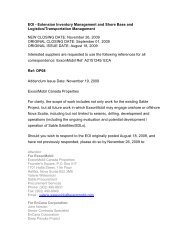
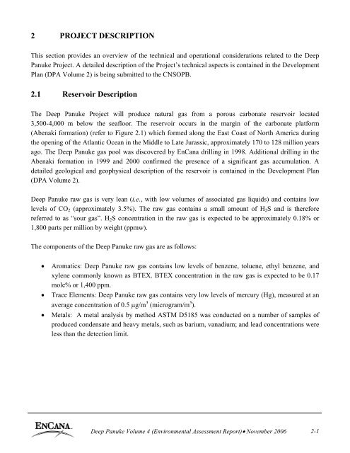
2 PROJECT DESCRIPTIONThis section provides an overview of the technical and operational considerations related to the <strong>Deep</strong><strong>Panuke</strong> <strong>Project</strong>. A detailed description of the <strong>Project</strong>’s technical aspects is contained in the DevelopmentPlan (DPA Volume 2) is being submitted to the CNSOPB.2.1 Reservoir <strong>Description</strong>The <strong>Deep</strong> <strong>Panuke</strong> <strong>Project</strong> will produce natural gas from a porous carbonate reservoir located3,500-4,000 m below the seafloor. The reservoir occurs in the margin of the carbonate platform(Abenaki formation) (refer to Figure 2.1) which formed along the East Coast of North America duringthe opening of the Atlantic Ocean in the Middle to Late Jurassic, approximately 170 to 128 million yearsago. The <strong>Deep</strong> <strong>Panuke</strong> gas pool was discovered by EnCana drilling in 1998. Additional drilling in theAbenaki formation in 1999 and 2000 confirmed the presence of a significant gas accumulation. Adetailed geological and geophysical description of the reservoir is contained in the Development Plan(DPA Volume 2).<strong>Deep</strong> <strong>Panuke</strong> raw gas is very lean (i.e., with low volumes of associated gas liquids) and contains lowlevels of CO 2 (approximately 3.5%). The raw gas contains a small amount of H 2 S and is thereforereferred to as “sour gas”. H 2 S concentration in the raw gas is expected to be approximately 0.18% or1,800 parts per million by weight (ppmw).The components of the <strong>Deep</strong> <strong>Panuke</strong> raw gas are as follows:• Aromatics: <strong>Deep</strong> <strong>Panuke</strong> raw gas contains low levels of benzene, toluene, ethyl benzene, andxylene commonly known as BTEX. BTEX concentration in the raw gas is expected to be 0.17mole% or 1,400 ppm.• Trace Elements: <strong>Deep</strong> <strong>Panuke</strong> raw gas contains very low levels of mercury (Hg), measured at anaverage concentration of 0.5 µg/m 3 (microgram/m 3 ).• Metals: A metal analysis by method ASTM D5185 was conducted on a number of samples ofproduced condensate and heavy metals, such as barium, vanadium; and lead concentrations wereless than the detection limit.<strong>Deep</strong> <strong>Panuke</strong> Volume 4 (Environmental Assessment Report)• November 2006 2-1
P:\EnvSci\101xxx\1015157 - <strong>Deep</strong> <strong>Panuke</strong>\Graphics\FiguresFigure2-01.cdrFigure 2.1Generalized Stratigraphy, Offshore Nova Scotia
Potential Radioactive Components: The presence of radon, a Naturally Occurring Radioactive Material(NORM), was measured during well testing by an RDA 200 Radon Detector. <strong>Deep</strong> <strong>Panuke</strong> raw gascontains very low levels of radon (Rn), in the range of 50-100 Bq/m 3 , equivalent to 1.4-2.7 pCi/Litre(Conversion factor: 1Bq = 27.027 pCi).The following sections describe the process by which EnCana proposes to develop this reservoir andproduce market-ready gas.2.2 <strong>Project</strong> Infrastructure ComponentsThe main <strong>Project</strong> infrastructure components include a mobile offshore production unit (MOPU), subseawells and flowlines, and a subsea pipeline to transport sales product to either Goldboro, NS (M&NPOption) or SOEP 660 mm [26 inch] pipeline tie-in (SOEP Subsea Option).A rendering of the proposed layout is presented in Figure 2.2.2.2.1 Mobile Offshore Production Unit (MOPU)The MOPU comprises the hull and topsides facilities. The hull includes all facilities and equipment thatwould normally be supplied with a mobile jack-up unit including jacking systems, legs, foundations,accommodations, helideck and utilities. The topsides facility will include all equipment required forprocessing hydrocarbon fluids from the reservoir. The topsides equipment will generally be located on topof the main deck but may also include equipment located within the hull, such as the central control room.The topsides facility will contain processing equipment to separate, measure, dehydrate, and sweeten theraw gas. Acid gas and water handling equipment will also be installed on the MOPU. Hydrocarbondew pointing will be required for the M&NP Option and the condensate will be used as the primary fuelfor power generation and compression. Currently, it is estimated that there will be no surpluscondensate produced beyond fuel usage; however, in the event that condensate must be injected, it willbe injected down-hole with the acid gas stream. For the SOEP Subsea Option, condensate separatedfrom the gas will be dehydrated, sweetened, and recombined with the export gas for delivery to the tie-infor the SOEP Subsea Option. The production facility is designed to export 8.5 x 10 6 m 3 /d [300MMscfd].<strong>Deep</strong> <strong>Panuke</strong> Volume 4 (Environmental Assessment Report)• November 2006 2-3
Figure 2.2Proposed Field RenderingP:\EnvSci\101xxx\1015157 - <strong>Deep</strong> <strong>Panuke</strong>\Graphics\FiguresFigure2-01.cdr
2.2.2 Subsea Wells and FlowlinesThe initial development well program will consist of re-completing four existing production wells (H-08, M-79A, F-70, and D-41), drilling one new injection well (D-70) in Margaree (EL 2387), and onenew production well (H-99) in <strong>Panuke</strong> (PL 2902). Up to three new production wells could be drilledafter first gas in Cohasset (PL 2901), <strong>Deep</strong> Cohasset (SDL 2255H), <strong>Panuke</strong> (PL 2902) or Margaree (EL2387).All wells will be completed with horizontal subsea trees and tied back to the MOPU with individualsubsea flowlines and control umbilicals. All subsea flowlines and control umbilicals will be trenchedand buried.2.2.3 Export PipelineEnCana proposes to transport sales product via a subsea pipeline from the offshore processing facility toone of two delivery points:• Goldboro, Nova Scotia (M&NP Option) to an interconnection with M&NP; or• SOEP 660 mm [26 inch] pipeline tie-in (SOEP Subsea Option) at a close point on the pipelineroute.The <strong>Deep</strong> <strong>Panuke</strong> export pipeline will have a capacity of 8.5 x 10 6 m 3 /d [300 MMscfd] at meanenvironmental conditions. The proposed routes of the export pipeline will minimize its footprint byusing existing pipeline and flowline corridors where practical. The pipeline details for both options arepresented in Table 2.1. All values are approximate.Table 2.1Export PipelinePipeline Diameter Pipeline Length (km)Pipeline Phases(mm [inch])M&NP Option 560 [22] 176 (includingSingle phaseapproximately 3 kmonshore)SOEP Subsea Option 510 [20] 15 Multi-phaseFor the SOEP Subsea Option, the export pipeline tie-in point will be at a subsea location. The tie-infacility will likely consist of a hot tap tie-in assembly and a valve tie-in assembly. Each assembly will besecured to the seabed using piles and surrounded by a subsea protection structure. Final processing ofthe <strong>Deep</strong> <strong>Panuke</strong> fluids will be done by SOEP at the onshore plants near Goldboro, NS and PointTupper, NS.<strong>Deep</strong> <strong>Panuke</strong> Volume 4 (Environmental Assessment Report)• November 2006 2-5
The pipeline will be trenched where the water depth is shallow, as dictated by design requirements. Thiswill also reduce span correction and reduce the potential for sediment scour to the pipeline. The pipelinewill be designed to withstand impacts from conventional mobile fishing gear in accordance with the DetNorske Veritas (DNV) Guideline No. 13, Interference Between Trawl Gear and Pipelines, September,1997.The proposed offshore pipeline routes for both the M&NP Option and the SOEP Subsea Option arepresented on Figure 2.3. The following criteria were used to determine the proposed pipeline route:• Minimize the environmental effects, seabed disturbance, and effects to fisheries due to theinstallation and operation of the new pipeline.• Minimize the pipeline route length where possible while still satisfying all other route criteria.• Minimize the number of subsea pipeline and cable crossings. Where crossings are unavoidable,routing of the pipeline shall, where possible, have a crossing angle of greater than 30°.• Consider any known future pipelines.• Consider concerns raised by landowners and stakeholders.• The pipeline route shall be such that “normal” pipelay operations (pipelay vessel) are not precludedand appropriate minimum horizontal radius of curvature (to be defined during detailed design,dependent on the pipeline size and water depth) could be kept.• Consider approaches near the MOPU (which may be installed in advance of the pipelineinstallation) to ensure compliance with safety and layout requirements.• The shore approach routing shall be such to enable shore pull-in systems to be as simple aspossible. Due consideration shall be made of the existing SOEP pipeline in the close confines ofthe harbour.• Within the limits of the lay corridor and SOEP pipeline proximity requirements, route selectionshall minimize potential pre-lay works (pre-sweeping, etc.) and post-lay rectification requirementsfor freespans.<strong>Deep</strong> <strong>Panuke</strong> Volume 4 (Environmental Assessment Report)• November 2006 2-6
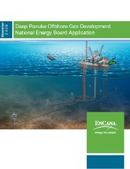
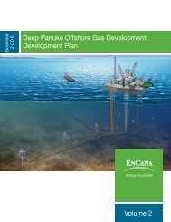
2.2.3.1 M&NP OptionThe proposed pipeline route for the M&NP Option extends 173 km and closely follows the existingSOEP gas pipeline. With the exception of a slight route change offshore due to the revised location ofthe field centre, the offshore pipeline routing for this option remains unchanged from the route outlinedin the approved 2002 CSR.2.2.3.2 SOEP Subsea OptionThe export pipeline to the SOEP Subsea Option tie-in point will be approximately 15 km in length. Thewater depth ranges from approximately 20 m to 45 m in depth and the seabed is relatively featureless. Itis anticipated that the pipeline for SOEP Subsea Option will be buried. The pipeline will traverse aregion of Sable Island Bank noted for its heterogeneous surficial geological characteristics. Thedominant substrates along the proposed route are well-sorted Sable Island sand and, to a lesser extent,gravel. Sand ripples and mega-ripples are common due to the influence of waves and currents. Thesurficial sediments of the pipeline route are under the influence of dynamic sediment transport regimes,with large volumes of sand moved during storm events. In contrast to the M&NP option, the SOEPSubsea Option pipeline will not traverse areas of rock outcroppings, basins or other notable geologicalfeatures.2.2.4 Onshore Pipeline and FacilitiesOnshore facilities are required for the M&NP Option only. In this option, EnCana’s onshore facilitywill consist of the physical components necessary for interconnection of EnCana’s natural gas pipelinewith M&NP’s facility. EnCana will install a pig launcher/receiver facility and a safety/emergencyshutdown valve system. The onshore facility will interface with the M&NP owned facility, which willinclude custody transfer meters, the final section of pipeline, and the tie-in to the existing M&NPpipeline. This facility is estimated to be 60 m x 45 m in area and will be enclosed by a security fence.The onshore pipeline will be located within the pipeline corridor indicated on Figure 2.6.<strong>Deep</strong> <strong>Panuke</strong> Volume 4 (Environmental Assessment Report)• November 2006 2-10
Gold BrookIsaacs HarbourGoldboro### ## #r "X#"XBettys Cove Brook###SOEP Gas PlantSealHarbourLake<strong>Deep</strong> <strong>Panuke</strong> <strong>Project</strong>Onshore Pipeline CorridorEnCanaEnCana ProposedPipeline CorridorEnCana ProposedOffshore Pipeline RouteExisting PipelineM&NP PipelineTerrestrial Features# Small StreamSmall Stream - (Intermittent / Subsurface)"X Good Four-toed Salamander HabitatWetlandDeer Wintering AreaGeocaulon lividum Distributionr Geocaulon lividum (~29 Stems)Topographic FeaturesLand Cover RoadsWatercourse MajorWaterbody%UNo CoverForestedFigure 2.6MinorService/TrackAbandonedProposed Keltic/Maple Property BoundaryWharfPipeline TrestleMooring/Berthing DolphinsN%U%U%U%U%U%UDrum Head0 500MetresMap Parameters<strong>Project</strong>ion: Universal Transverse Mercator (UTM)Zone: 20Datum: NAD 83Scale: 1:15,000Date: October 24, 2006<strong>Project</strong> Number: 1015157X:\<strong>Project</strong>s\NovaScotia\NSD15999\AV_<strong>Project</strong>s\<strong>Panuke</strong>_Working.apr
The onshore portion of the pipeline will be approximately 2 to 4 km in length. Design criteria for theonshore pipeline include the following:• consideration of physical features such as rock outcrops;• minimizing environmental effects through avoidance of Deer Wintering Areas;• minimizing pipeline length;• minimizing impact on wetlands through avoidance where feasible;• minimizing impact on stream crossing by use of dry crossing techniques;• consideration of pipelay restriction, such as minimum horizontal radius of curvature;• minimizing effects on landowners’ properties through which the pipeline will run; and• ensuring best use of industrial park land consistent with the Municipality’s conceptual plan forthe park.The environmental constraints on the pipeline route and expected mitigation measures to manage theseconstraints will be included in the Request for Quote for the onshore pipeline installation package.Additionally, onshore environmental constraints will be considered in the <strong>Project</strong>’s EnvironmentalProtection Plan (EPP).An access road may be required which will likely run parallel to the new pipeline. The final location ofthe onshore facilities will depend on the final pipeline routing and access, as well as biophysical, socioeconomicand engineering constraints. When additional survey work is completed, EnCana will consultwith the land owners in the Goldboro Industrial Park to determine the location of the onshore facilities,as well as the onshore pipeline route.Although layout of the onshore facilities is not complete at this time, Figure 2.7 is a schematic of thetypical onshore facility that would be required for the <strong>Deep</strong> <strong>Panuke</strong> <strong>Project</strong>.<strong>Deep</strong> <strong>Panuke</strong> Volume 4 (Environmental Assessment Report)• November 2006 2-12
~60mENCANAFACILITYM&NPFACILITYSalesGasFromOffshoreESDFlowMetering/GasCompositionSales GastoM&NP PipelineTemporaryPiggingReceiving~45mLiquidRemovalControls/CommunicationBuildingChain Link Fence PerimeterFigure 2.7Typical Onshore FacilityP:\EnvSci\101xxx\1015157 - <strong>Deep</strong> <strong>Panuke</strong>\Graphics\Figures\Figure2-07.cdr
2.3 Construction and Installation2.3.1 MOPU FacilitiesThe MOPU will be fabricated onshore, towed to the field, and jacked up on location. The MOPU willbe situated on specifically designed footings, such as spud cans or equivalent, similar to typical drillingjack-up rig footings. The topsides facilities will be fabricated separately and installed on the MOPU atan atshore location. The <strong>Project</strong> has no requirement for an offshore heavy lift.The hull portion of the MOPU is expected to utilize the basic design premise of an existing mobileoffshore drilling unit (MODU) jackup design with the minimum number of changes required to acceptthe topsides production facilities. Some modifications are expected for additional safety and controlsystems, which must be integrated platform wide and other specific modifications, includingappurtenances, risers, and umbilicals, which interface with the sea and seabed below. However, theintent will also be to minimize the deviations to the standard MODU design so that re-conversion of theunit back to a drilling unit in future can be readily accommodated if desired. The MOPU hull will bebased upon a typical jack-up drilling rig fabrication method; however, the associated drilling equipmentwill not be installed.The hull designs must be structurally capable of withstanding the environmental design conditions foroffshore Nova Scotia on a year round basis; these MODUs are generally referred to a “harshenvironment jack-up rigs”.The production topsides will house all the production equipment and will be located on the hull in theareas where the drilling package is normally located. The topsides will be constructed in modularformat. The expected weight of the production facilities is 6,000 tonnes and a single module is preferredfrom a construction and commissioning viewpoint. However, multiple modules can also be utilizedshould this be a better fit for the selected hull. Final arrangement will be determined during detaileddesign.The modules will be designed to be lifted or skidded onto the hull structure and will be supported by themain girders within the hull.The accommodations unit(s) will be designed to be constructed within Nova Scotia and therefore mayhave a design and build plan which will allow for transportation to the integration site and integration ofthe unit with the remainder of the MOPU, if required. Special considerations will include design ofinterface systems for power and utilities as well as load out and lifting considerations. Theaccommodations unit will be designed for a minimum of 68 persons on board (POB) and steady statePOB of approximately 30 persons; however, it could also be larger if the MOPU contractor chooses to<strong>Deep</strong> <strong>Panuke</strong> Volume 4 (Environmental Assessment Report)• November 2006 2-14
use a standard MODU accommodations design to allow for easier conversion back to MODU operationsin the future. Final accommodations size and layout will be determined during detailed design and willnot impact the predictions of the EA Report.The flare structure will also be designed to be constructed in Nova Scotia and therefore must alsoaccommodate the loadout, transport, and installation considerations similar to the accommodationsunit(s). The flare structure is expected to be a tubular lattice type structure and may be vertical or aboom type configuration. It will be in the order of 70 m above the topsides production facilities top mostdeck and will house the high pressure and low pressure flare lines and flare tips.The topsides module(s) and the MOPU hull will likely be fabricated at separate locations and thenbrought to a common yard where they will be integrated. The topside(s) will be installed onto theMOPU hull and the remaining construction work will be completed. It is crucial to the effectiveness ofthe offshore phase that all the construction work is complete and commissioned as far as possible priorto the MOPU sailing away for installation.Installation activities include the transportation and installation of the completed MOPU.During the early stages of the detailed design phase of the <strong>Project</strong>, it will be important to ensure that theMOPU is designed to be transportable by the most economical means. Accordingly, until the MOPUfabrication yard is known, it will be essential to maintain design flexibility.The actual installation of the MOPU at the offshore location is the same as the installation of a typicaljack-up drilling rig. That is, the MOPU jacking system will be activated to raise the hull above the sealevel to its final design elevation.Installation will be in accordance with installation manuals which will provide full details of thesequence and content of each operation. The <strong>Project</strong>’s EPP will be integrated with the development ofthe installation manuals. The following summarizes the installation activity for the MOPU:• tow the MOPU to the offshore site;• jack the MOPU legs down to the seafloor;• jack the hull out of the water to the pre-loading elevation;• perform pre-loading operations to jack the hull to the final design elevation; and• installation of scour protection material (if required).<strong>Deep</strong> <strong>Panuke</strong> Volume 4 (Environmental Assessment Report)• November 2006 2-15
2.3.2 Export PipelineA proposed pipeline corridor has been selected as described in Sections 2.2.3 and 2.2.4 and shown onFigures 2.3 to 2.6.For the M&NP Option, the route will head towards the existing SOEP pipeline and then follow thepreviously approved route paralleling the existing SOEP pipeline to shore. The two lines will beapproximately 1 km apart, except where on bottom topography necessitates close proximity. In the nearshore area, approximately 7 km from land, the two lines will be approximately 100 m apart.For the SOEP Subsea Option, the route will head towards a close tie-in location.Preliminary route studies for the SOEP Subsea Option as well as the M&NP Option pipeline routeaffected by the field centre change have been completed. Detailed route studies will be conductedduring detailed design to confirm and refine preliminary routing and construction methods. Pipelineswill be hydrostatically tested during commissioning.Nearshore and offshore pipeline installation activities as presented in the approved 2002 CSR have notchanged; therefore, these activities are not addressed in this section as there is no need to re-assess.However, further to the pipelay information provided in the approved 2002 CSR, refer to Section 2.3.5which provides additional detail on methods involving sediment disposal.2.3.3 Subsea Tie-In FacilitiesFor the SOEP Subsea Option, sales product is transferred from the <strong>Deep</strong> <strong>Panuke</strong> MOPU via a 15 km,510 mm [20 inch] export pipeline to the existing SOEP 660 mm [26 inch] pipeline. The connection tothe SOEP pipeline will be by a subsea tie-in, referred to as a “hot tap”. The hot tap process involves theconnection of a tee (i.e., branch nipple) and an isolation valve onto the existing pipeline through which a“coupon” can be cut out of the existing pipeline while the pipeline is still operational. The branch nippleconnection can either be attached by welding or installing a mechanical clamp.“Welded” hot tap activities can be described as follows:• expose buried pipeline section by airlifting sediments;• remove weight and corrosion coating;• install and commission welding habitat;• inspect pipeline;• weld branch nipple onto pipeline;• install reinforcement sleeve;<strong>Deep</strong> <strong>Panuke</strong> Volume 4 (Environmental Assessment Report)• November 2006 2-16
• install branch nipple flange;• install isolation valve;• remove habitat;• install “hot tap” machine;• perform “hot tap”;• remove “hot tap” machine; and• install “hot tap” protection structure.“Mechanical” hot tap activities can be described as follows:• expose buried pipeline section by airlifting sediments;• remove weight and corrosion coating;• inspect pipeline;• install mechanical clamp;• install “hot tap” machine;• perform “hot tap”;• remove “hot tap” machine; and• install “hot tap” protection structure.The “hot tap” structure is connected via a spool piece to a <strong>Deep</strong> <strong>Panuke</strong> tie-in structure which houses theequipment that will be required at the end of the <strong>Deep</strong> <strong>Panuke</strong> export pipeline. This equipment includesa manual isolation valve, a check valve and provision for a temporary subsea pig receiver. A protectionstructure will be placed around each of the SOEP pipeline hot tap equipment and the <strong>Deep</strong> <strong>Panuke</strong>pipeline tie-in equipment.Refer to Section 2.3.5 which provides additional detail on methods involving sediment disposal withrespect to the hot tap installation.2.3.4 Subsea Flowlines and UmbilicalsA total of six to nine subsea flowlines will be installed on the seafloor to tie-in the five to eight productionwells and one injection well. It is expected that the subsea production flowlines will be 200 to 250 mm [8to 10 inches] in diameter and range from 1 to approximately 10 km in length. The injection flowline isexpected to be 75 mm [3 inches] in diameter and approximately 1.7 km in length. The flowlines may be aflexible or rigid design and may be installed by reel-lay or s-lay pipelay methods. The flowlines will betrenched and buried. Flowline lengths, diameters, and installation method will be confirmed during detaileddesign.<strong>Deep</strong> <strong>Panuke</strong> Volume 4 (Environmental Assessment Report)• November 2006 2-17
A dedicated subsea umbilical will be required for each well in order to control, monitor, and supplychemicals to the wells. All umbilicals will be trenched and buried.Offshore pipeline installation activities as presented in the approved 2002 CSR are applicable to the subseaflowline as well as umbilical installation and therefore are not addressed in this section as there is no need tore-assess. It should be noted that, while pipeline installation by reel-lay for flexible lines was notspecifically addressed in the approved 2002 CSR, there is no change in the assessment as both reel-lay ands-lay pipelay methods simply refer to the methods used to feed the pipeline from the vessel to the seabed.Further to the pipelay information provided in the approved 2002 CSR, refer to Section 2.3.5 whichprovides additional detail on methods involving sediment disposal with respect to subsea flowlines andumbilicals installation.2.3.5 Construction Methods Involving Sediment DisplacementThe <strong>Deep</strong> <strong>Panuke</strong> project has three infrastructure components that will require some form of sedimentdisturbance during the construction/installation phase. These components are as follows:• export pipeline (either M&NP Option or the SOEP Subsea Option);• flowlines; and• umbilicals.The activities, location, techniques, duration and amount of sediment disturbance are described in Table2.2 below. A summary for each component is described in the following paragraphs.2.3.5.1 Export PipelineFor the M&NP Option, the first kilometre from shore will be pre-trenched and covered with nativematerial. Alternatively, this may be replaced by a horizontal directional drill (HDD) section where thecuttings will be disposed of onshore. Approximately 50% of the remaining 173 km offshore section willbe trenched approximately 1 m into the seabed with natural or mechanical replacement of nativesediments.For the SOEP Subsea Option, the SOEP pipeline tie-in location will have to be exposed by airlifttechniques. The 15 km <strong>Deep</strong> <strong>Panuke</strong> export pipeline will be trenched approximately 1 m into the seabedwith natural or mechanical replacement of native sediments.<strong>Deep</strong> <strong>Panuke</strong> Volume 4 (Environmental Assessment Report)• November 2006 2-18
2.3.5.2 FlowlinesFlowlines for the five to eight production (18-31 km in total length) and one acid gas injection (1.7 km)will be trenched approximately 1 m into the seabed with natural or mechanical replacement of nativesediments.2.3.5.3 UmbilicalsUmbilicals for the five to eight production (18-31 km in total length), one acid gas injection (1.7 km)and gas buy-back valve, which forms part of the subsea isolation valve (SSIV) assembly (150 m), willbe trenched approximately 1 m into the seabed with natural or mechanical replacement of nativesediments.2.3.6 Subsea Equipment and Associated Protection StructuresThe following subsea equipment will be protected by dedicated protection structures:• wellhead (up to 9 in total);• hot tap (SOEP Subsea Option only, see Section 2.3.3);• tie-in (SOEP Subsea Option only, see Section 2.3.3); and• SSIV skid (protection structure may not be required since SSIV is located in MOPU SafetyZone).These shall be separately deployed structures. The protection structures shall be designed to allowadequate access to the wells for all planned diver and remotely operated vehicle (ROV) interventiontasks. The SSIV assembly shall be designed to support the piping and valves and to provide protectionagainst dropped objects. All subsea protection structures will be trawlable, cage-like, open tubularconstruction. The protection structures footprint is expected to be approximately 10 m x 10 m for thewellheads, 10 m x 6 m for the hot tap, 20 m x 15 m for the tie-in, and 5 m x 5 m for the SSIV skid.<strong>Deep</strong> <strong>Panuke</strong> Volume 4 (Environmental Assessment Report)• November 2006 2-19
Table 2.2 Construction MethodsCategory Activity/Purpose Location Technique(s) DurationExportPipeline –SOEP OptionExpose the existing SOEP 660mm [26 inch] pipeline to perform“hot tap”Trenching of the export pipelinefor on-bottom stability.Approximately KP162 of SOEPpipeline. See Figure 2.315 km length from MOPU toSOEP hot tap location. See Figure2.3AirliftMulti pass plough (MPP), MPP withseparate back fill plough (BFP), jetting,mechanical digger with natural ormechanical replacement of nativesediments1-2 days (for mechanicalhot tap) or 2-4 days (forwelded hot tap)On average 150 to 400 m/hr(dependent on soilconditions)AmountApprox. 10m x 10m x3m for welded hot tapApprox. 5m x 5m x3m for mechanical hottapTrench to allow 1m ofcoverExportPipeline –M&NPOptionHorizontal directional drilling*ortrench of approximately first 1kmof pipeline from onshore for onbottomstability and protection.KP0 to KP1.0. See Figure 2.4For trenching, trench by a dipper/floatingbackhoe/floating grab dredge. Someblasting may be required in nearshore area(in the dry during periods of low tide)3 to 4 months Pipeline will be laid inpre-excavated trenchand covered withnative materialFlowlinesTrenching of the export pipelinefor on-bottom stability.Trenching of approx. 31 km of200 to 250 mm [8 to 10 inch] and1.7 km of 75mm [3 inch]flowlines for insulation,protection and on-bottom stabilityApprox. KP1.0 to KP22.0 andKP110.0 to the MOPU. See Figure2.3See Figure 2.2MPP, MPP with separate BFP, jetting,mechanical digger with natural ormechanical replacement of nativesedimentsMPP, MPP with separate BFP, jetting,mechanical digger with natural ormechanical replacement of nativesedimentsOn average 150 to 400 m/hr(dependent on soilconditions)On average 150 to 400 m/hr(Dependent on soilconditions)Trench to allowapproximately 1m ofcoverTrench to allowapproximately 1m ofcoverUmbilicals Trenching of approximately 31km of 100 mm [4 inch] umbilicalsfor flowlines and buy-back gasvalve.See Figure 2.2MPP, MPP with BFP, jetting, mechanicaldigger with natural or mechanicalreplacement of native sedimentsOn average 150 to 400 m/hr(dependent on soilconditions)Trench to allowapproximately 1m ofcover* Horizontal directional drilling of this section would not displace surface sediments. HDD cuttings will be disposed of onshore.<strong>Deep</strong> <strong>Panuke</strong> Volume 4 (Environmental Assessment Report)• November 2006 2-20
2.3.6.1 Pile DrivingThe <strong>Project</strong> basis in the approved 2002 CSR comprised three bottom-founded platforms. Each platformwas to be fastened to the seabed via 2100 mm [84 inch] diameter skirt piles driven 61 to 68 m below theseabed. The piles were to be driven with a Menck MHU-1700 Hammer (or equivalent). This hammerhas a maximum energy output of 1.70 million Newton-meters (1.25 million foot-pounds). The pileswere to be approximately 75 m in length and the water depth was approximately 37 m. As a result,approximately 40 to 45% of the hammer impacts would have occurred underwater with the remainder inair. The pile driving duration was estimated to be 4 to 6 hours per pile based upon previous experiencewith the <strong>Panuke</strong> and Cohasset platform piles.In the approved 2002 CSR, a SSIV assembly was to be situated approximately 150 m from theproduction platform. It was anticipated that the SSIV assembly may have been pre-fabricated onto askid for ease of installation and may have required a protection frame. The skid/protection frame mayhave been fastened to the seabed via four piles ranging in size from 610 mm [24 inch] to 910 mm [36inch] driven approximately 8 to 12 m below seabed. These piles would be driven with an IHC S-90 (orequivalent) hammer which has a maximum energy output of 89,000 Newton-meters (66,000 footpounds).The actual pile driving duration is estimated to be 0.5 to 1 hours based upon previousexperience with the <strong>Panuke</strong> platform docking piles.The revised <strong>Project</strong> design basis is based upon having a MOPU with subsea production wellsindividually tied back to the MOPU. The MOPU does not require any piles for installation. There maybe up to eight subsea production wells and one acid gas injection well. Each wellhead will require aprotection structure. The sales product(s) will be either exported to shore (M&NP Option) or to theexisting SOEP pipeline (SOEP Subsea Option). A SSIV assembly will be required for both options asper the design basis approved in the approved 2002 CSR. For the SOEP Subsea Option, the connectionto the SOEP pipeline will be via a “hot tap” which will in turn be spool connected to a <strong>Deep</strong> <strong>Panuke</strong>“tie-in” structure.As a result, the following subsea protection structures will be required for the revised <strong>Project</strong> designbasis:• wellhead (up to 9 in total);• SSIV assembly skid (1);• hot tap (1) (SOEP Subsea Option only); and• tie-in (1) (SOEP Subsea Option only).<strong>Deep</strong> <strong>Panuke</strong> Volume 4 (Environmental Assessment Report)• November 2006 2-21
These subsea structures may be fastened to the seabed via four piles ranging in size from 610 mm [24inch] to 910 mm [36 inch] driven approximately 8 to 12 m below seabed. These piles would be drivenwith an IHC S-90 (or equivalent) hammer which has a maximum energy output of 89,000 Newtonmeters(66,000 foot-pounds). The actual pile driving duration is estimated to be 0.5 to 1 hours basedupon the previous experience of driving the <strong>Panuke</strong> platform docking piles.Although the total number of piles has increased for the revised <strong>Project</strong> design basis, the diameter andlength of the piles is smaller requiring an overall shorter duration of the activity with a lower energyhammer. As a result, the potential pile driving requirements associated with the 2006 <strong>Project</strong> basis isless than the <strong>Project</strong> basis approved in the 2002 CSR; refer to Table 2.3 for comparison.2.3.7 Onshore Facilities and Pipeline (M&NP Option Only)Onshore pipeline installation activities as presented in the original CSR have not changed; therefore,these activities are not addressed in this section as there is no need to re-state.2.3.8 Development Well ConstructionDevelopment wells will include five to eight production wells and one injection well, all of which willbe subsea. A jack-up drilling unit will be used to complete the existing wells and to drill the subseawells. A jack-up drilling unit is a MODU that has legs that can be jacked up or down. Once towed to thesite, the legs are jacked down until they are in contact with the seafloor, then the rig platform is elevateduntil it is approximately 25 m above the water surface. The jack-up drilling unit will remain on locationduring drilling and completion operations and then be removed. Well construction activities areexpected to take approximately 430 days (five new drill wells at 60 days each plus four re-entry wells at32 days each) in total to complete.The normal drilling program for all <strong>Deep</strong> <strong>Panuke</strong> wells involves conventional hole and casing/pipesizes. All casing designs are based on CNSOPB Offshore Petroleum Drilling Regulations.<strong>Deep</strong> <strong>Panuke</strong> Volume 4 (Environmental Assessment Report)• November 2006 2-22
Table 2.3Pile Driving Details<strong>Project</strong> Design Basis of 2002 Approved 2002 CSRWellhead PlatformProductionPlatformUtilities andQuarters PlatformNo.PilesSize [mm (in)]4 2100 (84) 61842100(84)2100(84)SSIV Skid 1 4 610-910 (24-36) 8 - 12Revised <strong>Project</strong> BasisNo.PilesSize [mm (in)]WellheadProtection (x9) 36 24 - 36 8 - 12Penetration[m] Hammer Size Max. Energy ]N.m (ft. lbs)] Actual Driving Duration/PileMenck MHU-1700(or equivalents)68 Same as WHP65 Same as WHPIHC S-90(or equivalents)1,699,000(1,253,000)1,699,000(1,253,000)1,699,000(1,253,000)89,000(66,000)ActualDrivingDuration4 to 6 hr 16hr - 24hr4 to 6 hr 32hr - 48hr4 to 6 hr 16hr - 24hr0.5hr - 1hrEstimated Total Duration 2 (Menck MHU-1700)Estimated Total Duration 3 (IHC S-90)Penetration[m] Hammer Size Max. Energy [N.m (ft. lbs)] Actual Driving Duration/pileIHC S-90(or equivalents)Hot Tap 4 24 - 36 8 - 12 Same as WellheadTie-in 4 24 - 36 8 - 12 Same as WellheadSSIV Skid 1 4 24 - 36 8 - 12 Same as Wellhead2hr - 4hr64hr - 96hr2.7 d – 4 d2hr - 4hrActualDrivingDuration89,000(66,000) 0.5hr - 1hr 18hr - 36hr89,000(66,000) 0.5hr - 1hr 2hr - 4hr89,000(66,000) 0.5hr - 1hr 2hr - 4hr89,000(66,000) 0.5hr - 1hr 2hr - 4hr1 May not be required since in Platform/MOPU Safety Zone2 Approximately 40 to 45% of the duration is under water hammer activities3 All the duration is underwater hammer activitiesEstimated Total Duration 3 (IHC S-90)24hr - 48hr1d - 2d<strong>Deep</strong> <strong>Panuke</strong> Volume 4 (Environmental Assessment Report)• November 2006 2-23
For the new production and injection wells drilled, the conductor pipe (first string of pipe) will be setapproximately 100 m below the seafloor. This is the same method that has been used on the existingsuspended delineation wells. This section will be drilled primarily with seawater and viscosifiers to aidin ensuring cuttings removal from the wellbore. These cuttings are deposited at the seabed and aregenerally equivalent to the volume of the hole drilled, approximately 65 m³.The conductor pipes will serve as the primary weather barrier to take environmental loading and protectthe inner strings of casing (length of pipe) while drilling the well. The conductors also take the surfaceloading implied by the other strings of casing that are returned to the mudline suspension system. Oncethe drilling has been completed, the conductors will be removed and the well will be converted to asubsea wellhead. With the production tree installed, a high pressure riser will be required to tieback tothe surface blowout preventor (BOP) stack. The high pressure riser will be designed to withstand theenvironmental loads as well as all internal design loads.All wells, including production and injection, will set the surface casing into the Wyandot member atapproximately 950 m below sea level in the general direction that the bottom of the well will be located.The BOP stack is then installed on top of the surface casing prior to drilling the intermediate holesection.For the re-entry wells, an intermediate hole section has been drilled just into the top of the limestone atapproximately 3200m true vertical depth (TVD). An intermediate casing string has been set 20 m intothe Abenaki 7/6 formation and cemented back just above any potential hydrocarbon bearing sands(~2300 m). The new production well(s) will be similarly constructed to the existing suspendeddelineation wells. Prior to drilling the reservoir section and with the well secured, the surface wellheadand conductor will be removed and the well will be converted to a subsea wellhead. The production treewill be installed with high pressure riser connected back to the surface BOP stack.A rotating BOP and an injection spool will be installed with the surface BOP stack in preparation forannular velocity control (AVC) drilling techniques and the main hole section will be drilled through theproductive interval of the carbonate reef. On the re-activation wells, the reservoir section has beendrilled to a total depth of circa 3650 m TVD which is about 150 m past the gas-water contact (GWC) at3504 m TVD. On many of the delineation wells, this GWC was not clearly evident while drilling thesection as the formation was not porous at this depth, however it was clearly identified while drilling theMarCoh D-41 well. On each of the wells to be re-used for production, a liner (string of pipe) has beeninstalled across the reservoir section and cemented back to the previous casing shoe. For the newproducing well(s), the reservoir section may be left open, with no liner in place, in order to maximize theflow potential of the well.<strong>Deep</strong> <strong>Panuke</strong> Volume 4 (Environmental Assessment Report)• November 2006 2-24
For re-entry of the existing wells, a “trash cap” will first be removed from the conductor stub 3 m above theseafloor. A “trash cap” is a cylinder device closed on one end that sets over the conductor to keep outmarine organisms or falling debris. Once the trash cap has been removed, a running and retrieving tool isused to back off the temporary abandonment caps. Each of the wells then has a cement plug set that has tobe drilled out.The production wells will all be completed with a downhole packer (plus other ancillary downholeequipment), production tubing, surface controlled subsurface safety valve, a tubing hanger, and a subseaproduction tree. Once all hydrostatic tests and function tests are performed, the production wells will beopened for clean-up flow on the drilling rig. This will remove any water or debris from the wellboreprior to handover for production operations on the MOPU. See Figure 2.8 for details on the productionwells.The injection well will be drilled using similar processes and procedures as with the production wells.Once the surface casing is set in the Wyandot formation, the main well bore will be drilled vertically tothe injection zone in the Upper Mississauga formation located at approximately 2400 m TVD. SeeFigure 2.9 for details on the injection well. Similar to the production well, the completion for theinjection well will consist of tubing, downhole packer, subsurface safety valve, tubing hanger andinjection tree.For the M&NP Option, it is estimated that there will be no surplus condensate produced beyond fuelusage; however, the ability to inject condensate down-hole with the acid gas stream provides operationalflexibility in times of maintenance and/or operational issues. It is currently planned to inject thecondensate with the acid gas into the one injection well that will be drilled west of the MOPU fieldcentre. Injection pumps on the main production platform will be used to pump the condensate down thewell at the required pressures for injection into the downhole disposal zone.This injection well for acid gas and condensate (if necessary) will be drilled into a porous and permeablezone in the Upper Mississauga Formation; the targeted injection zone is the Tidal-Fluvial Sandstone.The impermeable Naskapi shales located directly above will prevent any migration of injected acid gasor condensate. The Upper Mississauga Formation will be capable of containing the entire acid gas andsurplus condensate volumes that will be produced over the life of the <strong>Project</strong>. Migration of injectionfluids to other formations and/or to the surface is considered extremely unlikely. The possibility of acidgas injection souring the <strong>Panuke</strong> oil zone is also considered to be extremely unlikely. See Figures 2.8and 2.9 for production and injection well schematics.<strong>Deep</strong> <strong>Panuke</strong> Volume 4 (Environmental Assessment Report)• November 2006 2-25
Figure 2.8Typical Production Well SchematicP:\EnvSci\101xxx\1015157 - <strong>Deep</strong> <strong>Panuke</strong>\Graphics\Figures\Fig2_8.cdr
Figure 2.9Acid Gas Injection Well SchematicP:\EnvSci\101xxx\1015157 - <strong>Deep</strong> <strong>Panuke</strong>\Graphics\Figures\1015157_Figure2-09.cdr
2.3.8.1 Drilling Fluid ProgramWater-based muds (WBM) will be used in development drilling. These muds are used to protect andclean the drill hole, for overbalancing formation pressures, and for bringing cuttings to the surface. Theselection of the drilling fluid is based on factors such as the hole angle, the formation types drilled(mudstone, sandstone, clays, etc.), and the time of exposure.WBM is a suspension of solids and dissolved material in a carrier base fluid of water. WBM tends to beused for wells that are normally pressured or do not encounter difficult geology. Based on theexperience gained while drilling the <strong>Deep</strong> <strong>Panuke</strong> delineation wells, it was determined that only WBMwill be used for any new development drilling activities.The typical composition of WBM (seawater gel mud type) for <strong>Deep</strong> <strong>Panuke</strong> are as follows:• barite;• bentonite;• potassium chloride (KCl);• polymers;• water;• glycol;• soda ash/sodium bicarbonate/lime;• caustic soda; and• salt (sodium chloride or calcium chloride).During drilling of the new wells, the mud is circulated down the drillpipe from the drilling unit to thebottom of the wellbore and returned to the drilling unit in the annular space (between drill pipe and openhole/casing) carrying the cuttings from the well. Each hole section of a wellbore requires different fluidproperties. Thus after each hole section, the mud is modified or changed out. WBM that is no longerrequired will be disposed of overboard, along with WBM cuttings in accordance with the OffshoreWaste Treatment Guidelines (OWTG) (NEB et al. 2002).For the wells to be re-entered and completed, some drilling is required to remove cement suspensionplugs. This will be done using a viscosified brine solution and so traditional drilling mud will not berequired. Prior to removal of the last suspension plug on the existing wells, the well will be displacedwith filtered completion brine which will act as an overbalanced annulus fluid for setting the productionpacker. Some viscous pills of polymer gelled brine may be used to ensure removal of all solid particlesin the wellbore. The completion fluid will be clear brine with additives for corrosion and oxygeninhibition as well as H 2 S scavengers.<strong>Deep</strong> <strong>Panuke</strong> Volume 4 (Environmental Assessment Report)• November 2006 2-28
Once the well completion is set and the production tree is in place, it will be necessary to flow the wellto clean up and remove completion fluids from the reservoir. This operation will be done using a welltest package installed on the drilling rig. In order to flow the well, it is necessary to provide anunderbalance for the well to flow naturally. This underbalance can be achieved in a number of waysbut, in general, involves lowering the density of the completion fluid inside the tubing string. It istypically not recommended to use fresh water to lower fluid density in a gas well as this can lead to theformation of hydrates. Circulating nitrogen into the completion tubing is one alternative to loweringfluid density but tends to be equipment intensive on the drilling rig. Another alternative is to displacesome of the completion fluid in the tubing string with either diesel or glycol or a combination of both.This will likely be the method used for <strong>Deep</strong> <strong>Panuke</strong> wells. The underbalanced fluid column, alsoreferred to as the “fluid cushion”, is caught by the well test equipment on the drilling rig and burnedthrough the oil burner on the flare boom. Typically this represents a very small volume of diesel in theorder of 20 to 30 m³.Through the life of the field, workovers will be required in the wellbores. These workovers will requirevarious pieces of equipment to be sent offshore to perform downhole work. Completions brines may beused during these processes. These brines will be composed of water and a salt formulation kept insuspension using a viscosifier (polymer).2.3.9 Hydrostatic TestingThe export pipeline for both M&NP and SOEP Subsea Options and the production and injectionflowlines will be hydrostatically tested. It may be necessary to treat the seawater introduced into thepipeline with corrosion inhibitors and biocides as these chemicals protect the interior surface of thepipeline if the time between the installation of the pipeline and its commissioning into service exceedsthe timeframe allowed for leaving untreated seawater in the pipeline. Leaving untreated seawater in thepipeline for more than one month can establish conditions which permit corrosion to occur at a laterstage in the life of the pipeline. The introduction of treatment chemicals is a safety measure for theprevention of corrosion over the life span of the pipeline.The hydrostatic test plan for the export pipeline is detailed in Table 2.4 and the following paragraphs.For the export pipeline (M&NP Option), the discharge of hydrostatic fluids occurs at the MOPU. Thecooling water pumps, running at 2400 m 3 /hr, will be flowing into the discharge caisson whiledischarging the hydrostatic fluid. This provides a dilution factor as outlined in the table below. There isno dilution for the export pipeline (SOEP Subsea Option) since the release point is at the tie-in location.For the flowlines, hydrostatic fluids may be discharged at the MOPU or at the individual subseawellheads. This will be confirmed during detailed design. Therefore, no dilution for the flowlines isassumed as a worst case scenario.<strong>Deep</strong> <strong>Panuke</strong> Volume 4 (Environmental Assessment Report)• November 2006 2-29
Table 2.4 Hydrostatic Fluid Discharge SummaryCaseLength[km]Release PointReleaseVolume [m 3 ]ReleaseRate[m 3 /hr]CoolingWater Rate[m 3 /hr]DilutionFactorExport Pipeline176 Field Centre 43,200 400 2400 6:1(M&NP Option)Export Pipeline15 SOEP Subsea 3040 400 n/a n/a(SOEP Subsea Option)Tie-in locationProduction Flowlines18.2 Field Centre 590 175 n/a n/a(at start-up)Production Flowlines12.4 Field Centre 402 175 n/a n/a(after start-up)Acid Gas Injection Flowline 1.7 Field Centre 8 24 n/a n/aAlthough assessed in the previously approved 2002 CSR, hydrostatic testing must be re-assessed due tochanges in dilution factors, location of release, and additional pipeline and flowlines scenarios.For both the M&NP Option and the SOEP Subsea Option, the pipeline will be installed cleaned, gauged,flooded, and hydrotested. The pipeline spool between the pipeline and MOPU will be installed and thepipeline will be leak tested, dewatered, dried and nitrogen packed. For the M&NP Option, the fluid willbe disposed at the MOPU location. For the SOEP Subsea Option, the fluid will be disposed at the SOEPsubsea tie-in location.The flowlines will be installed cleaned, gauged, flooded and hydrotested. The flowline spool betweenthe pipeline and MOPU will be installed and the flowline leak tested. For the flowlines, it is unknown atthis time whether the fluid will be discharged at the MOPU location or at the individual wellheadlocations. This will be determined during detailed design.All the water introduced into the line shall be thoroughly filtered to 50 microns. During filling,cleaning, gauging and hydrostatic testing, chemical inhibition package(s) will be continuously injectedinto the seawater. The chemical inhibition package may include: dye to aid in the detection of leaks; abiocide to control marine organisms and sulphate reducing bacteria; a corrosion inhibitor; and adissolved oxygen scavenger to minimize corrosion on the interior of the pipeline. During the fillingcycle, some spillage of this water may occur at the pig receiving station offshore. This occurs whenexcess hydrostatic water is required to push the pig into the pig receiver at the end of the pipeline.The chemicals to be used in this application will be approved for discharge through the OffshoreChemical Selection Guidelines (OCSG) (NEB et al. 1999) and selected from a list of chemicalsapproved for use in Canada. Since the installation program for the pipeline is still under developmentand a supplier has not yet been selected, the definitive treatment chemicals cannot be specified.<strong>Deep</strong> <strong>Panuke</strong> Volume 4 (Environmental Assessment Report)• November 2006 2-30
A study, consisting of two components, will be undertaken to confirm predictions there will be minimaleffects of the selected chemicals discharged into the environment. A toxicity bioassay program (firststudy component), will be undertaken prior to discharging these compounds. The bioassay will employsamples of the proposed chemical diluted in seawater to emulate the mixtures of chemicals andconcentrations proposed for the hydrostatic test program. The results will be applied in a plumedispersion model (second study component) to confirm that there will be minimal effect to the marineenvironment around the platform. Prior to undertaking this study, the parameters and scope of thebioassay study will be discussed with Environment Canada and DFO.The onshore section of the pipeline will also require hydrostatic testing, which may be conductedconcurrently with the offshore section of the pipeline as discussed above, using the same seawatersource and treatment chemicals.Should the schedule of the onshore section of the pipeline installation be changed, then a separatehydrostatic test may be required. Under this circumstance, the hydrostatic test water could be left in theonshore pipeline until the offshore testing is completed and the hydrostatic test water discharged withthe offshore hydrostatic test water.2.4 Operations2.4.1 ProductionProduction facilities on the MOPU will be operated to optimize production while maintainingenvironmental protection and high safety standards and minimizing environmental impact. Theproduction facilities will be staffed on a 24-hour basis. Facility maintenance and inspectionrequirements will be managed through a maintenance management system that will incorporateproactive and predictive methods as well as intelligent condition monitoring techniques.Production facilities will consist of equipment for separation, metering, amine sweetening, acid gasinjection, dehydration, hydrocarbon dewpoint control (M&NP Option only), produced water treatmentand disposal, condensate treatment, condensate injection (M&NP Option only), feed gas and export gascompression, and utilities. A simplified process flow diagram is presented as Figure 2.10.For the M&NP Option, all production and treatment facilities are located offshore. For the SOEPSubsea Option, production and treatment facilities are primarily located offshore but the export gas andliquids will be routed to the existing SOEP facilities near Goldboro and, subsequently, Point Tupper forfurther processing.<strong>Deep</strong> <strong>Panuke</strong> Volume 4 (Environmental Assessment Report)• November 2006 2-31
Acid GasInjectionFeed GasCompressionGasSweeteningSweet GasDehydrationHydrocarbonDewpointControlSales/ExportGasCompressionSales/ExportMarinePipelineSubseaProductionWellsInletSeparationCondensateTreatmentFuelCondensateFor PlatformEnergyGeneration(M&NP Option)CondensateFor Export(SOEP SubseaOption)OnshoreThird PartyGasProcessing(SOEP SubseaOption)ProducedWaterTreatmentWaterDisposalPotentialSurplusCondensateInjection(M&NP Option)SalesGas toThird PartyPipelineCoolingWaterFigure 2.10Simplified Process Flow DiagramP:\EnvSci\101xxx\1015157 - <strong>Deep</strong> <strong>Panuke</strong>\Graphics\Figures\Figure2-10.cdr
For the M&NP Option, the export gas will be “on specification” sales gas meeting the hydrocarbondewpoint and water content requirements for the M&NP pipeline. As a result, there is no onshoretreatment required. The sales gas will be routed to shore near Goldboro in a new 560 mm [22 inch]pipeline with a connection into the existing M&NP pipeline. Onshore facilities are related tometering/quality measurement and isolation valve requirements only. The liquids will be treatedoffshore and used as fuel. Currently it is estimated that there will be no surplus condensate producedbeyond fuel usage. To allow flexibility in times of maintenance and/or operational issues, condensatewill be commingled with the acid gas and re-injected for disposal.For the SOEP Subsea Option, the export gas and condensate will be commingled and routed to theSOEP 660 mm [26 inch] pipeline and routed to the existing SOEP Goldboro gas plant. At Goldboro, thegas and liquids will be separated and the gas further processed into sales gas by SOEP and shipped viathe existing M&NP pipeline to market. The liquids will be routed to the SOEP Point Tupper liquidsplant for processing and sale.2.4.1.1 SeparationThe well fluids will be processed through the production or test separator for separation of the gas,condensate, and water.2.4.1.2 MeteringThe <strong>Deep</strong> <strong>Panuke</strong> production facilities will adhere to the applicable regulations and the Canada-Newfoundland Offshore Petroleum Board (CNOPB)/CNSOPB Measurement Guidelines, October 2003.2.4.1.3 Amine SweeteningThe amine sweetening system, which uses methyldiethanolamine (amine), is designed to remove theH 2 S contained in the raw gas. The removal of the H 2 S and CO 2 from raw gas results in a waste acid gasstream predominantly containing H 2 S and CO 2 . The H 2 S content of the raw gas during the life of the<strong>Project</strong> will vary. The amine sweetening system is designed to operate safely over the expectedvariation of H 2 S content in the raw gas.The <strong>Deep</strong> <strong>Panuke</strong> gas contains up to 3.5 mole % CO 2 and approximately 1,800 ppm H 2 S. The aminesweetening unit is designed to be fed with gas that contains up to 2,500 ppmv of H 2 S and up to 3.5 mole% CO 2 to provide some operational design flexibility. The facility metallurgical design will be for 3,000ppmv of H 2 S and 4.0 mole % CO 2 to provide some metallurgical design flexibility. The sales gasspecification requires the H 2 S content to be a maximum of 6 mg/m 3 (approximately 4 ppmv) and 3.0mole % CO 2 . The current design basis unit outlet is for an H 2 S level of 2 ppmv and CO 2 at 2.8 mole %.<strong>Deep</strong> <strong>Panuke</strong> Volume 4 (Environmental Assessment Report)• November 2006 2-33
Although the M&NP Option is the only option producing sales gas, the same product specificationrequirements will be met for SOEP Subsea Option as the SOEP facilities require a sweet feedstock.The amine-sweetening unit is based on physical absorption using a solvent to absorb the impurities (H 2 Sand CO 2 ). The solvent is then regenerated via heating to release the absorbed impurities. The process iscyclic, in which the amine is continuously circulated through the absorber/contactor to pick up theimpurities, then routed to a regenerator to release the impurities.Remaining CO 2 and H 2 S amounts not removed during the amine sweetening process remain in the salesgas, which is sent to market. The amine-sweetening unit is a closed loop system.The amine solvent used in the sweetening unit will be methyldiethanolamine, which will improve theselectivity between H 2 S and CO 2 absorption. The cyclic process can result in a build up of impurities inthe amine solvent over time. If the amine solvent requires a change, whether complete or partial (diluteout the impurities), it is removed from the process and shipped to shore for reclaiming (manufacturer toclean and recycle). Production will be halted when a complete change-out of amine solvent is required.The change-out of the amine solvent will be subject to the EPP.2.4.1.4 Acid Gas HandlingAcid gas from the amine regenerator will be compressed to approximately 15,100 kPa (from a feed pressureof 150 kPa) using a multi-stage compressor. Water condensing between the compressor stages recycledback to the processing facilities. The compressed acid gas will be injected into a suitable, subsurfacereservoir. Table 2.5 describes the design flow and composition for the acid gas injection system.The <strong>Project</strong> does have the capability to flare acid gas. The capability to flare the acid gas stream isrequired to provide operational flexibility in times of maintenance and/or operational issues.Table 2.5 Acid Gas Injection System – Composition and Flow<strong>Description</strong>Design DataMass Flow (kg/h) 8100STD Gas Flow (m 3 /hr) 5325Molar Flow (kgmole/hr) 230Pressure (kPa) 150Temperature (C) 56Component Mole %CO 2 63.2H 2 S 18.5CH 4 17.0C2 + 1.1H 2 O 0.24Note: The flow represents the total feed to the acid gas management system including acid gas from the amine system andH 2 S removed from the condensate fuel for the Mean Production Profile (Mean denotes the statistical Mean value of aprobability distribution).<strong>Deep</strong> <strong>Panuke</strong> Volume 4 (Environmental Assessment Report)· November 2006 2-34
2.4.1.5 DehydrationSweet gas from the amine-sweetening unit contains water that must be removed prior to hydrocarbondewpoint adjustment (M&NP Option) or prior to export (both options). The gas dehydration unit is aliquid desiccant process utilizing a solvent to absorb the water. The solvent, triethylene glycol (TEG), isthen regenerated via heating to release the absorbed water. The process is cyclic in which the TEG iscontinuously circulated through the absorber/contactor to pick up the water then routed to a regeneratorto release the water. A brief description of the process follows.Treated gas from the amine unit is routed to the TEG system for dehydration. The gas first is routed tothe TEG contactor in which the incoming gas flows counter current to the lean TEG. The lean TEGabsorbs the entrained water in the gas stream and reduces the water content of the gas.The rich TEG leaving the contactor cools the regenerator overheads and is routed to the TEG flashdrum. The flashed gas from the flash drum is routed to the flare. The flash drum liquids then passthrough the TEG charcoal filter (to remove trace hydrocarbons) and the TEG filter (to remove charcoal)before being heated in the TEG regenerator feed/effluent heat exchanger before entering the regenerator.The bottoms of the regenerator are heated to remove the water from the rich TEG. A small amount ofstripping gas is used to enhance the water removal of the regenerator. The regenerator overheads arecooled for tower top temperature control, with the overhead gas stream being routed to the flare.The water removed from the sweet gas dehydration process is removed from the top of the TEGregenerator in the overhead gas stream and routed to the low-pressure (LP) flare header. A large portionof the water in the overhead gas stream will condense in the flare piping or drum. The flare drumliquids will be pumped into either the inlet or test separators and the water portion of the liquids in theseseparators is routed to the produced water treating facilities. Non-condensable hydrocarbons will beflared.The lean glycol leaves the regenerator column, enters the TEG surge drum, then is cooled in the TEGregenerator feed/effluent heat exchanger. The lean TEG is further cooled in the lean TEG cooler(cooling medium cooler) before entering the TEG contactor.The dry gas from the TEG contactor passes through a coalescer to reclaim any entrained TEG leavingthe contactor in the overhead gas stream. The TEG is returned to the flash drum. The dehydrationprocess is a closed loop system. The circulating TEG builds up contaminants, primarily salts. Once thelevels build to a point, the risk of corrosion and or deposits increase to the point where removal ofsome/all the TEG is required and new TEG added. Rate of build up varies with the feed quality so it isdifficult to predict how long before this happens.<strong>Deep</strong> <strong>Panuke</strong> Volume 4 (Environmental Assessment Report)• November 2006 2-35
Spent TEG has no measurable H 2 S and will be disposed of an approved facility.2.4.1.6 Hydrocarbon Dewpoint ControlFor the M&NP Option, the dehydrated gas from the TEG system is cooled via the Joule-Thompson (JT)effect by dropping the pressure of the gas. A portion of the gas stream condenses (condensate), which isthen separated. This step will be done offshore as it is necessary to satisfy pipeline gas specificationrequirements.For the SOEP Subsea Option, the export gas routed to the SOEP 660 mm [26 inch] pipeline need notmeet sales gas specification requirements. For these cases, hydrocarbon dewpoint control operationswill be done via the SOEP gas plant existing facilities.2.4.1.7 Condensate Treatment for FuelRecovered condensate will be treated via stabilization to remove light ends and H 2 S. The light ends andH 2 S thus released are recycled back to the raw gas stream for processing.For the M&NP Option, condensate is burned on the MOPU as the primary source of fuel. Operation ofthe condensate stabilizer will remove H 2 S in order to minimize air emissions and to produce a fuelmeeting the turbine driver requirements. Given that the amount of condensate is a function of raw gasrate thus declining over the life of the <strong>Project</strong>, it will be supplemented with natural gas as necessary tomaintain adequate fuel levels.The SOEP Subsea Option, all recovered condensate will be routed to the shore based SOEP facilities forseparation, processing, and sale.Condensate production is based on the production profile for the <strong>Project</strong>. The production profile hasbeen calculated for a range of reservoir gas compositions. The intent is that the MOPU will be designedfor the entire possible range. Over the range, the facility will produce less condensate than that requiredfor fuel thus no surplus condensate will exist for the M&NP Option.The MOPU will have some minimal storage for condensate. This storage is, approximately 55 m 3 andrepresents approximately five hours of consumption at full rate. The intention of this storage is to coverperiodic production upsets with enough time to allow for short term troubleshooting and/or swingingfuel from condensate to either fuel gas or diesel. The storage tank is a pressure vessel that is pressuredwith inert gas with excess pressure routed to the flare.<strong>Deep</strong> <strong>Panuke</strong> Volume 4 (Environmental Assessment Report)• November 2006 2-36
For the M&NP Option, it is estimated that there will be no surplus condensate produced beyond fuelusage; however, the ability to inject condensate down-hole with the acid gas stream provides operationalflexibility in times of maintenance and/or operational issues. The probability of the acid gas injectionwell malfunctioning and becoming inoperable is very low (
Table 2.7 Water CompositionComponentAbenaki 5 Formation Water (mg/l)Na + 29,163K + 513Ca 2+ 5,885Mg 2+ 950Ba 2+ 8Sr 2+ 448Fe 2+ 0Mn 2+ 0Cl - 55,321-HCO 3 731-CO 3 02-SO 4 1,570Produced water will be treated to a target dispersed oil concentration of 25 mg/L (30-day weightedaverage). The OWTG (NEB et al. 2002) specify a 30-day weighted average of 30 mg/L. The followingis a brief description of the treatment process.Prior to discharge, produced water is treated in several ways. Water from the inlet separator, testseparator, condensate stabilizer surge drum, and stabilizer feed filter coalescers is commingled androuted directly into the produced water feed drum. Water from other LP vessels is typically routed tothe closed drains header, which is routed to the LP flare drum. Liquids from the LP and high-pressure(HP) flare drums are routed to either the inlet or test separators.The function of the water feed drum is to hold produced water until sufficient volume is available toroute to the hydrocyclones. The small amount of gas from this drum is routed to the acid gas injectioncompressor. At the start of the field life, the water rates are anticipated to be very low, such that batchprocessing in the hydrocyclones is likely. As the water rates increase, the flow will be continuous.The hydrocyclones will remove all but trace amounts of liquid hydrocarbons. The hydrocyclones oiloutlet is routed to the closed drains. The water is continuously routed to cartridge-style produced waterpolishers to further reduce trace amounts of liquid hydrocarbons.The water is then heated in the produced water stripper feed preheaters prior to entering the producedwater stripper. The amount of heat will be adjusted to aid in the H 2 S removal capabilities of the strippertower. The produced water stripper tower is a packed counter current gas/liquid stripping column inwhich sweet fuel gas flows upwards counter current to the water to remove H 2 S; preliminary indicationssuggest that H 2 S will be lowered to a concentration between 1 to 2 ppmw. The gas from the stripper isrouted to the acid gas injection compressor.<strong>Deep</strong> <strong>Panuke</strong> Volume 4 (Environmental Assessment Report)• November 2006 2-38
The flow to the stripper column will change dramatically over the field life. It may be necessary toprovide flow via recycle or process in batches during low flow periods.The water outlet of the stripper is sampled for oil and H 2 S and routed overboard. The waste gas fromthe produced water stripper will be routed to the acid gas injection compressor for injection. This willbe the normal mode of operation. The plant does have the capability to divert the produced waterstripper gas to the flare in the event of a malfunction of the acid gas injection well and/or compressor. Ifthe produced water stripper gas were flared, it would be a maximum of 980 kg/h of 19.7 MW gascontaining 1.5 mole % H 2 S.The concentrations of amine and TEG in produced water at the outlet to the sea are below thoseconcentrations which would impact marine species. Studies on the eco-toxicity ofmethyldiethanolamine and TEG, undertaken by the manufacturers, indicate that these substances are oflow toxicity to fish and invertebrates in the concentrations present in the produced water discharge andthat these substances are readily bio-degradeable (Woodburn and Stott, undated).Currently the design envisages platform-based laboratory facilities for verification of produced watermeasurements.The produced water will be routed overboard via the discharge caisson where it will mix withapproximately 2,400 m 3 /hr of seawater which is used for process cooling purposes.2.4.1.9 CompressionFor the M&NP Option, the sales gas will be compressed on the platform for delivery to shore. Theexpected sales gas discharge pressure on the platform is approximately 13,000 kPa. The <strong>Deep</strong> <strong>Panuke</strong>compressor system is composed of three 7 MW units for a total of 21 MW of compressor power. Thecompressors will be used for sales gas export and feed gas. The feed gas service will be to account fordeclining reservoir pressure. These compressors will be tri-fuel (condensate, fuel gas, and diesel).For the SOEP Subsea Option, the export gas will be compressed on the platform for delivery to theexisting SOEP 660 mm [26 inch] pipeline and subsequently routed to shore. The expected export gasdischarge pressure on the platform is approximately 13,000 kPa. Like the M&NP Option, the <strong>Deep</strong><strong>Panuke</strong> compressor system is composed of three 7 MW units for a total of 21 MW of compressionpower. The compressors will be used for gas export and feed gas. The feed gas service will be toaccount for declining reservoir pressure. These compressors will be dual-fuel (fuel gas and diesel).<strong>Deep</strong> <strong>Panuke</strong> Volume 4 (Environmental Assessment Report)• November 2006 2-39
2.4.2 Utilities2.4.2.1 Electrical Power GenerationElectrical power generation for the <strong>Deep</strong> <strong>Panuke</strong> MOPU will be provided by multiple redundant fuelturbine generating sets. For the M&NP Option, the turbines will be tri-fuel (condensate, fuel gas, anddiesel). For the SOEP Subsea Option, the turbines will be dual-fuel (fuel gas and diesel). For the firstproduction start-up, sufficient quantity of diesel will be available for power generation.Emergency power will be provided by a diesel engine driven generator set as per CNSOPB regulations.The design requires the use of diesel fuel for emergency situations (emergency generator, firewaterpumps), for certain start up scenarios (i.e., when buy back gas is not available), and for certainmaintenance scenarios (i.e., power generators when no buy back gas is available).The transfer of diesel from ships to the MOPU storage tanks will occur via loading hose. Bulktransfer/hose-handling procedures will be outlined in the EPP.Battery back-up will be provided for critical emergency services.2.4.2.2 Platform FuelFor the M&NP Option, condensate will be used as fuel. Fuel gas may also be used as supplemental fuel,as required. For the SOEP Subsea Option, fuel gas will be the primary fuel source. Diesel will be usedas fuel for the crane and the emergency generator. Diesel will also be used for start-up and shutdown ofthe compressor and power generation turbines. The MOPU will have a storage capacity ofapproximately 70 m 3 for diesel. The area around the diesel storage will be “bunded” or “dyked” tocollect diesel fuel in the unlikely event of a leak/spill. The bunded area will be routed to the open drainssystem within which the hydrocarbon is recovered. There is no capability to flare diesel on the MOPU.All fuel will be metered.2.4.2.3 Heating Medium SystemThe processing facilities require heat input for a number of systems including amine regeneration, TEGregeneration, condensate stabilization, and produced water processing. The heating system is a “closedcircuit” system in which a heating medium (essentially the same solution as per the cooling mediumexcept it contains some stabilization additives) is pumped through waste heat recovery units (WHRUs).There are three WHRUs, one installed on each turbine exhaust of the compressors. The heating<strong>Deep</strong> <strong>Panuke</strong> Volume 4 (Environmental Assessment Report)• November 2006 2-40
medium, circulating through the WHRUs, extracts heat that would be destined as waste to ambient androutes to various users.2.4.2.4 Cooling Medium SystemCooling water for process and utility systems will be done via an indirect seawater/cooling mediumsystem. Seawater will be pumped through a filter then a heat exchanger. The exchanger will cool amixture of ethylene glycol and water (cooling medium). The cooling medium will then be distributed tothe equipment and the plant requiring cooling. The once through seawater is returned to the ocean viathe discharge caisson.2.4.2.5 Deck DrainageDeck drainage will be collected and treated according to the OWTG (NEB et al. 2002). Drainage fromequipment areas on platforms will be directed through a header system to a collection tank to anoil/water separator treatment unit on the MOPU. Petroleum hydrocarbons and sludge in the oil/waterseparator will be transferred into containers for shipment to shore for disposal. The water from theoil/water separator will be treated using a cartridge-style water polisher and tested prior to discharge toensure compliance with the discharge criteria of 15 mg/L or less.The deck drainage system does have overflows to permit water to be routed directly overboard in theevent of a deluge event or rain water in excess of the design condition.2.4.2.6 Relief and Blowdown SystemSafety systems and devices will be designed to meet <strong>Project</strong> standards and the requirements of allapplicable standards, codes, and local regulations, including:• API B31.3 – Piping;• API 14C – Cause and Effects;• API 520, 521 – PSV’s/Rupture Discs;• IEC 61508 – Functional Safety System;• ANSI/ISA-84.01-1996 – Safety Instrumented Systems;• NFPA 72E – Automatic Fire Detectors; and• NORSOK-1-002 – Safety and Automation System.The principal elements of the relief and blowdown system include the pressure relief devices, flarepiping system, flare separator, flare structure and the flare burner. The flare design will take place duringdetailed design. Application of all relevant codes will be followed for the system design. The system<strong>Deep</strong> <strong>Panuke</strong> Volume 4 (Environmental Assessment Report)• November 2006 2-41
will be designed considering emergency shutdowns, blocked discharges, fire exposure, tube rupture,control valve failure, thermal expansion and utility failures.Scheduled activation of the relief and blowdown system will occur for planned tests and inspection ormaintenance work. When the system is commissioned and activated, hydrocarbons will be safelydirected to the flare system. The flare will be designed to prevent any impact on the helideck and theliving quarters during worst-case weather scenarios.2.4.2.7 Inert Gas SystemThe <strong>Project</strong> will include an inert gas system. Inert gas is necessary for commissioning and start-upexercises as well as ongoing operations. The main use of the inert gas is in the gas compressor seals.The inert gas may also be used as a blanketing or purging gas to displace hydrocarbon vapours andreduce the risk of explosion and fire.2.4.2.8 Instrument AirInstrument air will be produced by electric driven air compressors and used in the instrumentation andcontrols system. The air will be dried.2.4.2.9 Breathing AirA breathing air system will be included in the design of the <strong>Project</strong>. Breathing air will be required foremergency purposes and for routine maintenance activities.2.4.3 Support and ServicingSupply vessels and helicopters will be used to supply personnel, fuel, food, well construction equipmentand other materials required to maintain production, construction, and well construction operations.Typically, helicopters will be used for regular crew changes, visits from regulatory agencies, servicepersonnel and other visitors that need to be transported to and from the offshore facilities.2.4.3.1 Support VesselsSupply vessels will be used to provide the platform operations with materials. Supply vessels will holdliquid drill mud, drill water, potable water, barite (weighting material), fuel, cement, bentonite (freshwater gel), drill pipe, casing and various equipment necessary for well construction operations,production operations and construction. It is anticipated that supply vessels will make periodic roundtrips from a dockside shorebase in Nova Scotia to the platform operation between two and four times a<strong>Deep</strong> <strong>Panuke</strong> Volume 4 (Environmental Assessment Report)• November 2006 2-42
week during normal operations. It is anticipated that there will be approximately six trips a week duringconstruction and heavy maintenance periods. In addition, a standby vessel is required near the platformat all times as per CNSOPB regulations.2.4.3.2 HelicoptersPersonnel will be transported to and from the offshore facilities via helicopters from the heliport locatedat the Halifax International Airport. During pipelay and heavy lift activities, the frequency of helicopteractivity is estimated to be two to three trips per week. During hook-up and commissioning, thefrequency is estimated to be seven to ten trips per week. The frequency will reduce to approximately sixto ten flights per month during operations. These helicopters are used primarily to transport crewmembers, company personnel and service personnel. In some cases, small equipment and parts aretransported via air transportation.2.4.4 <strong>Project</strong> Safety ZonesEnCana will consult with the appropriate regulatory authorities to develop a safety zone around the<strong>Deep</strong> <strong>Panuke</strong> facilities in accordance with the Nova Scotia Offshore Petroleum Drilling Regulations andthe Nova Scotia Offshore Area Petroleum Production and Conservation Regulations. This zone willinclude, as a minimum, an area extending 500 m around the MOPU and will likely also include theinterfield flowlines and wellheads. The exact configuration of the safety zone will be determined basedon safety risk assessment studies and consultations with the regulatory agencies. There will also be atemporary 500 m safety zone around the drilling rig when it is on location for development drilling. ANotice to Mariners will be issued and appropriate mariner charts will be updated for the installationsthrough the Canadian Hydrographic Service.Standard operating procedures will be developed to lessen the risk of collisions between ships and<strong>Project</strong> infrastructure. These would include, but are not limited to, the following:• presence of structures and safety zones would be indicated on nautical charts;• Coast Guard Notice to Mariners would apply during construction; and• radio operators would notify approaching vessels of the presence of the structures. The distanceat which mariners would be notified would be dependent on a number of factors, including thedirection and speed of the approaching vessel and weather conditions.Although there are no regulations under the CNSOPB that provide a similar safety zone around apipelaying vessel, EnCana will request the Coast Guard issue a Notice to Mariners with regard to thistemporary construction activity. Mariners will be informed as to the status of the pipelaying operationand the vessels taking part in the activity. The export pipeline’s design takes into consideration fishingactivity in the area so that once the pipeline is laid, there will be no restrictions with regard to safety<strong>Deep</strong> <strong>Panuke</strong> Volume 4 (Environmental Assessment Report)• November 2006 2-43
zones over the pipeline although there will be fishing restrictions over the subsea connection to theSOEP pipeline for the SOEP Subsea Option. As with the installation and interfield flowlines, nauticalcharts will be updated for the export pipeline through the Canadian Hydrographic Service.2.4.5 Onshore FacilitiesIn addition to the onshore pipeline, other onshore facilities will include a pig launcher/receiver facilityand a safety/emergency shutdown valve system. Periodic mechanical, electrical, instrumentation andgeneral housekeeping maintenance will be performed. For example, valves, piping, or general lightingwill require routine maintenance. Site visits will take place periodically.EnCana will take care to avoid use of invasive species in post-construction revegetation efforts and willplace a clear priority on the use of native species. Vegetation management will be conducted mainly bymechanical means and will be confined to the RoW. Herbicide use will be restricted to valve sites andmeter stations and will involve low application rates of compounds with low persistence and low ecologicaltoxicity. Herbicides will not be used within close proximity (e.g., 30 m) of watercourses or wetlands.2.5 Decommissioning and AbandonmentThe mean production life of the <strong>Project</strong> is anticipated to be 13.3 years; however, the resource forecastshow a probable production life ranging from 8 to 17.5 years. The design life is 20 years for thetopsides and 25 years for the remaining <strong>Project</strong> structures. As is common in the industry, facility lifecould be extended beyond 20 years with appropriate technical and maintenance activities in the eventreservoir productivity or additional resources prolong the life of the <strong>Project</strong>.The following facilities will require decommissioning and abandonment:· MOPU;· subsea production and injection wells;· subsea facilities;· offshore gas export pipeline;· onshore pipeline (M&NP Option only); and· onshore facilities (M&NP Option only).Decommissioning and abandonment of these facilities will be performed in accordance with theregulatory requirements applicable at the time of such activities. An action plan for decommissioningwill be submitted to the appropriate authorities for approval prior to commencement ofdecommissioning and abandonment activities.<strong>Deep</strong> <strong>Panuke</strong> Volume 4 (Environmental Assessment Report)· November 2006 2-44
Requirements for eventual removal of facilities will be taken into account during detailed design.Although regulatory requirements could change prior to the time of decommissioning and abandonment,current practices would see the facility degassed, degreased and cleaned to applicable standards, theMOPU towed to another location for re-use or retrofit, the wells abandoned and conductors cut belowthe seafloor, and the pipeline, flowlines and umbilicals flushed, cleaned, and abandoned in place. Thepotential presence of contaminants that could be encountered during recovery and transportation of thefacilities will be taken into account. Potential reuse of the MOPU will be considered on an economicbasis.Wells will be abandoned in compliance with applicable drilling regulations and according to standardindustry practices.With the exception of the pipeline, onshore facilities will be removed and the land restored inaccordance with applicable regulations. Buried onshore pipelines will be flushed, capped, andabandoned in place. The onshore pipeline RoW will be allowed to return to a natural state. Any abovegroundstructures associated with onshore pipelines will be removed. A Decommissioning Plan will bedeveloped for the <strong>Project</strong>, which will provide detailed procedures for decommissioning onshorefacilities.2.6 <strong>Project</strong> ScheduleThe <strong>Project</strong> Offshore Strategic Energy Agreement (OSEA), signed in June 2006, initiated the start of thenext <strong>Project</strong> phase. Consisting primarily of the regulatory approval process, major contract tenderingand negotiations, and a field centre bid competition, this phase is expected to be completed in the thirdquarter of 2007, with an expectation of project sanction in the third quarter of 2007. Assuming sanctionand after contract awards, the <strong>Project</strong> will engage in detailed engineering and procurement. Subsequentonshore fabrication at existing facilities will occur prior to installation offshore.Hull and topsides fabrication is scheduled to commence third quarter 2008, with the MOPU hull andtopsides ready for at-shore integration first quarter 2010.It is anticipated that the onshore and offshore sections of the export pipeline will be constructed either in2009 or 2010. The tie-ins to the MOPU and to either the M&NP facilities or to the SOEP pipeline willbe completed after the MOPU and the export pipeline installation is complete. Hook-up and offshorecommissioning activities will commence third quarter 2010 once the MOPU has been transported to thefield centre. First gas is anticipated to be produced in the fall of 2010.Well construction and completions will be completed with a separate mobile offshore drilling unit andwill be scheduled between 2008 and 2010.<strong>Deep</strong> <strong>Panuke</strong> Volume 4 (Environmental Assessment Report)• November 2006 2-45
2.7 Emissions and DischargesEnCana will adhere to the OWTG (NEB et al. 2002) and all applicable regulations for emissions andwaste management. Where no standards exist, best industry practice will guide EnCana. EnCana willminimize, to the extent practical, both the volumes of wastes being discharged and the concentration ofcontaminants entering the environment. A Waste Management Plan (WMP) (included in the EPP) willbe developed for the <strong>Project</strong> that will address all phases of the <strong>Project</strong> including construction,installation, operation, decommissioning, and abandonment. The goal of this plan is to minimizeoffshore wastes, discharges, and emissions and identify appropriate mitigative measures.Estimated quantities of wastes, discharges, and emissions that will be generated for both theconstruction/installation/drilling and production/operation phases of the <strong>Project</strong> are summarized in Table2.8. The table also includes summary descriptions of the characteristics of the waste discharges anddisposal procedures to meet regulatory compliance standards.2.7.1 Air EmissionsSources and types of air emissions during routine <strong>Project</strong> construction and operation will include:• exhaust from supply and stand-by vessels;• short-term flaring of the produced fluid from production wells during clean-up;• exhaust from machinery on the platform (e.g., gas turbines);• fugitive emissions (e.g., emission of volatile organic compounds from valves, filter changeouts,storage of hydrocarbons, etc.);• emissions associated with processing operations including continuous flaring for processing byproductsfrom TEG and produced water treatment systems; and• flaring of the full acid gas stream during routine maintenance of the acid gas management system(approximately 2% of operating time).The gas vented from the TEG regenerator must be continuously flared to prevent emissions of aromatichydrocarbons (BTEX) from the system. If the produced water stripping unit is required to remove residualH 2 S prior to disposal, the waste gas from this unit will be injected into the acid gas disposal well.Refer to Appendix F for details on the atmospheric modelling undertaken for their <strong>Project</strong>. Furtherinformation on routine air emissions, including generation rates, is presented in Table 2.8 and Section8.1. Information on air emissions during malfunctions and accidental events is provided in Section8.1.4.4.<strong>Deep</strong> <strong>Panuke</strong> Volume 4 (Environmental Assessment Report)• November 2006 2-46
Table 2.8 Routine <strong>Project</strong> Emissions/EffluentsType Emission/Effluent Estimated Quantity Characteristics Disposal StandardConstruction/Installation/DrillingAtmosphericEmissionsGenerator, engine andutilities exhaustsTemporary, minor CO 2 , SO 2 , NO x , TSP Atmospheric emissions will comply with the Air Quality Regulations(Nova Scotia Environment Act) and Ambient Air Quality ObjectivesDrill WasteDischargesLiquid Effluentfor OceanDischargeFlaring during wellclean-up and completionWBMWBM associatedcuttingsCompletion brineSanitary and food wasteExpected ~1/2 day perproduction (new and re-entry)well, unless otherwise requiredby operating requirements.Bulk surface release ofapproximately 700 m 3 of WBMfor production well; 600 m 3 forinjection well. WBM oncuttings is expected to be 244m 3 for each production welland 233 m 3 for injection well.Approximately 558 m 3 ofWBM associated cuttingsdischarged for each newproduction well to be drilled;487 m 3 for injection well.Approximately 1000 m 3 ofcompletion brine will bedischarged at the surface foreach new production well to bedrilled; 300 m 3 for each wellre-entry and the injection wellcompletion.Maximum capacity of thefacility during operation isapproximately 68 persons withan estimated volume of 20 Lper person per day; amountswill increase duringconstruction phase withincreased presence of vesselsand crews.Possible NOx, CH 4 , TSP,SO 2 , CO 2 , TPH, H 2 STypical constituentsinclude: barite, bentonite,KCl, polymers, NaHCO 3 ,lime, caustic soda, salt, andwaterRock cuttings coated withWBMWater-based brine, possiblyviscosifiersMacerated food, grey waterand sanitary waste(CEPA).Compliance with CNSOPB Production and Conservation Regulations(Section 32), Air Quality Regulations (Nova Scotia Environment Act)and Ambient Air Quality Objectives (CEPA).WBM will be disposed overboard. 1WBM associated cuttings will be disposed overboard. 1Completion fluid will be discharged overboard as permitted by theCNSOPB. 1Sanitary and food waste will be macerated to a particle size of 6 mm orless prior to ocean discharge. 1<strong>Deep</strong> <strong>Panuke</strong> Volume 4 (Environmental Assessment Report)• November 2006 2-47
Table 2.8 Routine <strong>Project</strong> Emissions/EffluentsType Emission/Effluent Estimated Quantity Characteristics Disposal StandardDeck drainage As generated Possible oily water withsome particulate matterRoof drainage will be directed overboard. 1 Deck drainage will betreated to reduce its oil concentration to meet regulatory requirementsocean discharge. 1Bilge/ballast water(Construction/Support vessels)Hydrostatic test fluids(Pipeline commissioningwater)As required Water with hydrocarbons Bilge/ballast water will be treated as necessary to reduce its oilconcentration to 15 mg/L or less prior to ocean discharge. 147,240 m 3 (over several days)see Section 2.3.4 for moredetails.Seawater containingbiocide and corrosioninhibitorsThe discharge of hydrotest fluids will require pre-approval fromEnvironment Canada.Solid WasteAir EmissionsMiscellaneous solidwastes (transported toshore)Flaring (acid gas duringroutine maintenance)Normal GeoturbineoperationsAs requiredConstruction materials,broken equipmentcomponents, packaging andshipping materials,damaged containers andgeneral debris and refuseassociated withconstructionProduction/OperationWastes will be sorted and disposed according to local regulatoryregime of the shore base, including the Nova Scotia Solid Waste-Resource Management Regulations and municipal requirements.Metals will be salvaged.refer to Table 8.3 H 2 S, SO 2 , NO x , CO 2 Atmospheric emissions will comply with the Air Quality Regulations(Nova Scotia Environment Act) and Ambient Air Quality Objectives(CEPA).refer to Table 8.3 SO 2 , NO x , CO 2 Atmospheric emissions will comply with the Air Quality Regulations(Nova Scotia Environment Act) and Ambient Air Quality ObjectivesProduced water refer to Table 2.6 Hydrocarbon, H 2 S in water(sour water)(CEPA).Produced water will be treated to a target dispersed oil concentration of25 mg/L (30-day weighted average). The OWTG specify a 30-dayweighted average of 30 mg/L. 1Liquid Effluentfor OceanDischargeCooling water 2,400 m 3 /h Chlorinated water;temperature 20EC aboveambient (before mixing incaisson)Deck drainage Pump capacity is 150 m 3 /h Rain and deluge water, maycontain oily water withsome particulatesMixed with produced water before discharge. Total residual freechlorine in cooling water will not normally exceed 0.25 ppm.Roof drainage flows directly overboard as permitted by CNSOPBguidelines. 1 Deck drainage will be treated to reduce hydrocarbons to
Table 2.8 Routine <strong>Project</strong> Emissions/EffluentsType Emission/Effluent Estimated Quantity Characteristics Disposal StandardBilge/ballast water As required Water with hydrocarbons Bilge/ballast water will be treated as necessary to reduce oilconcentration to 15 mg/L or less prior to ocean discharge. 1HazardousLiquids forOnshoreDisposalSolid WasteWell treatment fluids/Well completion andworkover fluidWater for fire controlsystemsAs requiredWell completion fluidshave similar properties toWBMFluids will be treated to an oil concentration of 40 mg/L or less prior todischarge. 1As required Excess deck drainage water Discharged overboard without treatment. 1Desalination brine 13 m 3 /hr Estimated salinity of 35-40pptWaste production fluids As requiredand by-productsMiscellaneous solidwaste (transported toshore)Miscellaneous solidwaste (transported toshore)As requiredAs requiredWaste residues in theproduction systemincluding oily sludge, scale,filters and filter residuesand chemical wastesDomestic solid waste andnon-hazardous solids suchas packing materialDomestic solid waste andnon-hazardous solids suchas packing materialDischarged overboard without treatment. 1Hazardous wastes will be accumulated in suitable containers andplaced in appropriate shipping containers for return to shore fordisposal and collected by licenced waste haulers. Provincial regulationsfor the storage, disposal, transport and management of used oilproducts will be followed as well as the Transportation of DangerousGoods Act as applicable.Wastes will be sorted and disposed according to local regulatoryregime of the shorebase, including the Nova Scotia Solid Waste-Resource Management Regulations and other municipal requirements.Wastes will be sorted and disposed according to local regulatoryregime of the shorebase, including the Nova Scotia Solid Waste-Resource Management Regulations and other municipal requirements.<strong>Deep</strong> <strong>Panuke</strong> Volume 4 (Environmental Assessment Report)• November 2006 2-49
2.7.1.1 Air PollutantsThe following describes criteria air pollutants (i.e., regulated by federal guidelines or provincial limits)emitted by the <strong>Project</strong>, although some may be emitted in minor amounts and may not necessarily resultin the effects described below unless otherwise indicated in Section 8.1.Nitrogen OxidesNitrogen oxides are produced in most combustion processes, and almost entirely made up of nitric oxide(NO) and nitrogen dioxide (NO 2 ). Together, they are often referred to as NO x . NO 2 is an orange toreddish gas that is corrosive and irritating. Most NO 2 in the atmosphere is formed by the oxidation ofNO, which is emitted directly by combustion processes, particularly those at high temperature andpressure, such as diesel engines. NO 2 is the regulated form of NO x . NO is a colourless gas with no directeffects on health or vegetation at ambient levels. The levels of NO and NO 2 , and the ratio of the twogases, together with the presence of hydrocarbons and sunlight are the most important factors in theformation of ground-level ozone and other oxidants. Further oxidation, and combination with water inthe atmosphere, contributes to the production of “acid rain”.Generally NO 2 constitutes 5 to 10% of the initial total emissions of NO x , and the conversion of themajority of NO occurs after emission to the atmosphere. Emissions information on boilers usually refersonly to total NOx, partly because the conversion rate of NO to NO 2 is somewhat site specific. Forinstance, the amount of NO 2 generated by a stationary combustion turbine can be calculated using theNational Emission Guidelines for Stationary Combustion Turbines set by the Canadian Council ofMinisters of the Environment (CCME). This is accomplished by taking into account the turbine’s poweroutput and heat output, which could potentially be recovered. Other methods for the assessment of NO xeffects include the ozone limiting method.For this <strong>Project</strong>, nitrogen oxides are produced primarily in the generation of power for electrical loadsand compressors. It is estimated that the compression load of 14 to 21 MW and expected electrical loadof 7 MW will be met through the use of combustion turbines.Sulphur DioxideSulphur dioxide (SO 2 ) is a colourless gas with a distinctive pungent sulphur odour. It is produced incombustion processes by the oxidation of sulphur in the fuel. SO 2 can, at high enough concentrations,cause damage to vegetation and adverse health effects impacting the respiratory system.This <strong>Project</strong> incorporates a sulphur management system that removes H 2 S from the gas stream andinjects it into a disposal well. In the event of maintenance requiring downtime, or a malfunction of the<strong>Deep</strong> <strong>Panuke</strong> Volume 4 (Environmental Assessment Report)• November 2006 2-50
acid gas injection system, the gas stream will be redirected to the flare which will result in limitedemissions of SO 2 .Total Suspended Particulate MatterTotal suspended particulate matter (TSP) is a measure of the particles in the atmosphere that are toosmall to settle out quickly, but remain suspended for significant periods of time. Generally, this meansparticles with an aerodynamic diameter of less than 44 µm. TSP is produced by mechanical processes,such as the abrasion of vehicle tires on unpaved roads, and by combustion processes. Most particulatematter formed by combustion is either mineral ash from the fuel, or hydrocarbons formed by incompletecombustion.This <strong>Project</strong> will result in construction-related emissions of particulate matter for necessary onshorecomponents of the <strong>Project</strong>; these emissions will be similar in type and scale to those created by othermedium to large sized construction projects. Offshore, the vessel exhausts will contain some particulatematter; these emissions are no more critical than those of similar vessels in everyday operation.Fine and Respirable Particulate MatterAlthough TSP is an excellent measure of the loading of particulate matter in the air, it does notnecessarily reflect the health risks of the particulate matter. Large aerodynamic particles are trapped bythe upper airways, and do not enter the lungs. Smaller diameter particles make their way to the lungs,and may become lodged there. Over the past few years, greater concern with regard to these fineparticles has led to research resulting in new sampling methods and criteria. In June, 2000, the CCMEadopted in principle Canada Wide Standards for particulate matter. Although these standards are not yetapplicable, they will be relevant in the future. These standards provide for a proposed PM2.5 standard of30 µg/m 3 for particulate
esult in eye irritation, respiratory system irritation, and higher concentrations can result in asphyxia.H 2 S is a by-product of decomposition of sulphur-containing organic material, and is associated withcertain natural gas deposits, including this <strong>Project</strong>. H 2 S has been safely managed in the natural gasresource sector. The relatively low levels of acid gas and the acid gas management system for this<strong>Project</strong> will result in the removal and elimination of H 2 S from the gas stream. In the unlikely event of afailure of the injection system and the extinguishing of the flare, there may be a brief period ofcontrolled H 2 S emissions to atmosphere from this <strong>Project</strong>. In the event of the even much less likelyscenario of a blowout of the injection well, there will be a release of H 2 S to the environment. In theevent of a blowout from a production well, H 2 S will be released as a component of the raw gas.2.7.1.2 Air Emissions ModellingIn order to predict the dispersion and subsequent effect of air emissions from the <strong>Project</strong>, a simulationwas conducted using a mathematical computer model of atmospheric transport. This method providesquantitative results and enables direct comparison of the simulated project effects with regulatorycriteria. For certain sources where the quantitative releases are too difficult to predict, an assessment hasbeen made based on the relative likelihood of releases, and the potential consequences. Modellingresults and environmental effects associated with significant air emissions are presented in Appendix Fand Section 8.1.2.7.2 Noise EmissionsNoise emissions will mainly be generated offshore during pile driving, blasting, and drilling operations.Other noise generating activities will include ship and air traffic of materials and personnel to offshorefacilities. Onshore noise will be limited primarily to construction of the pipeline and other onshorefacilities. The discussion presented in the approved 2002 CSR regarding noise emissions (offshore andonshore) remains valid (refer to Section 2.7.2 of the approved 2002 CSR). An updated discussion onnoise associated with pile driving is presented in Section 2.3.6.2.7.3 Electromagnetic EmissionsThe description of electromagnetic emissions presented in the approved 2002 CSR remains valid. Referto Section 2.7.3 of the approved 2002 CSR.<strong>Deep</strong> <strong>Panuke</strong> Volume 4 (Environmental Assessment Report)• November 2006 2-52
2.7.4 Drill Waste Discharges2.7.4.1 Use of Drill MudsAll drilling fluids (mud) go through a cyclic process during the drilling of a well. Prior to drilling aspecific hole section, the required type of mud must be prepared. It is either prepared onshore andbrought to the rig, or the required base products are brought to the rig and it is prepared onboard. Oncethe mud is ready for use, the drilling may begin for that hole section. The following describes the simplecycle that all drilling fluids follow:1. The mud is pumped down the drillpipe to the bit on the bottom.2. The mud comes out the bit and picks up the cuttings that the bit has produced and carries thesecuttings back to the rig on the outside of the drillpipe.3. Once back on the drilling rig, the cuttings (solid materials) are separated from the mud using solidscontrol equipment. Linear vibrating shakers plus periodic use of centrifuges are the maincomponents of the solids control equipment used to separate solids (cuttings from the wellbore) fromthe drilling mud.4. The clean mud returns to the original tanks for any minor modifications (additional products) beforestarting the cycle again.5. The cycle continues until the hole section reaches final depth.Once the final depth of the hole section is achieved, the mud is cleaned for re-use on the next holesection or it is removed from the rig to allow for the next drilling fluid for the subsequent operation.Bulk mud releases will be minimized by re-using mud on the next hole section or well if possible. WBMwill be released overboard during bulk releases.Typically, a conventional production well would be installed as follows:1. Drill and case the conductor hole, then prepare WBM and change drilling tools.2. Drill and case the surface hole, then change the mud system and drilling tools.3. Drill and case the intermediate hole section, then change the drilling tools.4. Drill and case the main hole section re-using the mud system from the intermediate hole section.5. Circulate the well to clean out drilling solids, displace drilling fluid from the wellbore to completionfluid and install the completion tubing / equipment.6. Provide underbalance and allow the well to flow to surface removing all completion fluids untilburnable gas at surface prior to handover to production.7. Secure the well and move the rig to the next well location and repeat the process.<strong>Deep</strong> <strong>Panuke</strong> Volume 4 (Environmental Assessment Report)• November 2006 2-53
Typically, a re-entry and completion of existing wells will be conducted as follows:1. Remove temporary abandonment caps and convert mudline suspension system to subsea wellhead.2. Install high pressure riser to rig tension deck and BOP stack.3. Drill out 340mm casing cement plugs and pull bridge plugs using suspension brine.4. Confirm well is secure and remove high pressure riser and BOP stack and install subsea productiontree.5. Drill out 245mm casing cement plugs and pull bridge plugs using suspension brine, change tools.6. Drill out 178mm casing cement plugs and pull bridge plugs using suspension brine.7. Filter and clean suspension brine to completion fluid specifications.8. Install the completion tubing/equipment.9. Provide underbalance and allow the well to flow to surface removing all completion fluids untilburnable gas at surface prior to handover to production.10. Secure the well and move the rig to the next well location and repeat the process.Spent WBM and associated drill cuttings will be discharged in accordance with the OWTG (NEB et al.2002).The conservative case of five new wells using WBM for all hole sections has been modelled with resultspresented in Appendix D.2.7.4.2 Drill Waste Discharge Behaviour and ModellingWhen cuttings and mud are discharged, the fine materials in the discharge form a turbidity plume nearthe sea surface, but the bulk of the material (cuttings) drops to the seabed with the fine materials beingstripped from the plume as it descends. Typically, a cuttings pile forms on the seabed near the dischargepoint. However, in high energy environments, like the <strong>Deep</strong> <strong>Panuke</strong> site, cuttings and fine particles andassociated metals, such as barium, are more likely to disperse rather than settle (refer to Appendix D).Barite is typically used to increase the density of the drilling fluid. It is also used to build small volumesof high density slugs used to trip drill pipe out of the hole dry. The type of drilling fluids used for <strong>Deep</strong><strong>Panuke</strong> wells will be salt-based and the density will be adjusted by increasing the concentration of salt inthe drilling fluid. Therefore, the use of barite will be minimized and generally only used for thepreparation of high density slugs to pull the drill pipe out of the hole dry.Oceanographic plume modelling for discharge of mud and cuttings at sea was conducted for surfacedischarge of WBM. See Section 2.3.4 for further details. The modelling of drill mud and cuttingsdischarges is based on the following assumed operational processes and volumes shown in Table 2.9.Modelling results of ocean disposal of drill waste discharges are presented in Appendix D.<strong>Deep</strong> <strong>Panuke</strong> Volume 4 (Environmental Assessment Report)• November 2006 2-54
Table 2.9 <strong>Deep</strong> <strong>Panuke</strong> Potential Drilling Waste Discharge SummaryEach New One New Each Re-entry Total DischargesProduction Well Injection Well Production WellSeabed release of WBM associated 131 131 0 656cuttings (m 3 )Surface release of WBM associated 427 356 0 2062cuttings (m 3 )Seabed release of WBM on180 180 0 900cuttings (m 3 )Surface release of WBM on64 53 0 309cuttings (m 3 )Surface release of WBM (bulk mud 700 600 0 3400release) (m 3 )Surface release of completion fluid 1000 300 300 5500(m 3 )Notes:All volumes are approximations that represent each well’s discharges.Using a conservative approach to dispersion modelling, it is assumed four existing wells will be re-completed using completion fluid (“reentry”production wells), and four new production wells and one new injection well will be drilled using WBM with overboard discharge.The completion fluid is a brine (NaCl) with various additives for oxygen scavengers, H 2 S scavengers and corrosion protection in somecases.Prior to use, all chemicals will be screened using the CNSOPB Offshore Chemical Selection Guidelines2.7.5 Effluent Discharges2.7.5.1 Produced WaterProduced water management is described in Section 2.4.1.8. Produced water will be treated to a targetdispersed oil concentration of 25 mg/L (30-day weighted average). The OWTG specify a 30-dayweighted average of 30 mg/L. Refer to Appendix D for results of produced water dispersion modelling.2.7.5.2 Cooling WaterThe cooling system will use seawater to indirectly cool a circulating medium (40% ethylene glycol, 60%water (volume)) solution. The cooling water flow rate will be constant at 2,400 m 3 /hr and will have atemperature approximately 15°C above background water temperature. It will be mixed with producedwater before discharge.The seawater is treated with chlorine generated by a sodium hypochlorite generator to prevent/reduce thegrowth of marine biological growth. The design chlorine concentration at the seawater lift pump inlet is 2ppm (1 ppm during normal operation with an increase during periods of high larval mussel concentration).The residual free chlorine concentration at the outlet will normally be below 0.25 ppm. The combinedproduced water and cooling water stream exit temperature will not exceed 25 o C above ambient.<strong>Deep</strong> <strong>Panuke</strong> Volume 4 (Environmental Assessment Report)• November 2006 2-55
2.7.5.3 Deck DrainageDuring construction and installation, prior to operation of the drains system, deck drainage will bedischarged overboard. Deck drainage water might contain traces of petroleum hydrocarbons, such aslube oils, helicopter fuel, and diesel fuel. Every effort will be made to prevent chemical contaminationon decks, which could be entrained into deck drainage. Storage areas for totes containing chemicals andpetroleum products will have secondary containment to prevent discharge onto deck surfaces.During the operation phase, deck drainage will be collected and treated according to the OWTG (NEB etal 2002). Drainage from equipment areas on the topsides will be directed through a header system to acollection tank to an oil/water separator treatment unit on the MOPU. Petroleum hydrocarbons andsludge in the oil/water separator will be transferred into containers for shipment to shore for disposal.The water from the oil/water separator will be treated using cartridge-style water polishers and testedprior to discharge to ensure compliance with the discharge criteria of 15 mg/L or less. The deckdrainage system does have overflows to permit water to be routed directly overboard in the event of adeluge event or rain water in excess of the design condition.Any spills of petroleum products (or other chemicals) will be cleaned up immediately and reported. Oilabsorbent pads and “oil dry” compounds will be available, at all times, in spill kits located at strategicsites on the platforms, to remove petroleum products from deck surfaces. The used absorbent materialsand any other oily wastes will be placed in sealed containers and returned to shore for treatment anddisposal at an approved waste management facility.EnCana will develop a <strong>Deep</strong> <strong>Panuke</strong> Emergency Management Plan (DPEMP) for the <strong>Project</strong> which willinclude a Spill Response Plan (refer to Appendix G) that will be submitted to the regulators for reviewand approval. It is the responsibility of all EnCana employees and contractors to report any accidents,incidents or spills to the Offshore Installation Manager for immediate action. The standby vessel in thefield will also be tasked as part of their regular duties to observe and report any spills from the facilities.2.7.5.4 Other Ocean DischargesOther ocean discharges (e.g., bilge/ballast, sanitary/food waste/testing waters, etc.) are summarized inTable 2.6 for the construction and operations phases of the <strong>Project</strong>. Those wastes, which are identified inthe OWTG (NEB et al. 2002) and other regulations, are included along with the compliance standard.Each waste stream will be treated or managed to make sure the discharges comply with the respectiveregulatory limits and EnCana’s environmental protection policies.<strong>Deep</strong> <strong>Panuke</strong> Volume 4 (Environmental Assessment Report)• November 2006 2-56
2.7.6 Naturally Occurring Radioactive Material (NORM)The description of NORM and appropriate management procedures presented in the approved 2002CSR remain valid. Refer to Section 2.7.6 of the approved 2002 CSR.2.7.7 Non-Hazardous Solid WastesThe discussion of non-hazardous solid wastes presented in the approved 2002 CSR remains valid. Referto Section 2.7.7 of the approved 2002 CSR.2.8 Hazardous Materials and WasteThe discussion of management of hazardous materials and waste presented in the approved 2002 CSRremains valid. This includes, but is not limited to, commitments by EnCana to adhere to all applicablefederal and provincial codes and regulations for the handling and transport materials. Refer to Section2.8 of the approved 2002 CSR.2.9 Environmental and Safety Protection Systems2.9.1 Equipment Inspection and MaintenanceAll <strong>Project</strong> equipment will meet the requirements of industry standards, and be certified as being safeand fit for its intended use. Purchase orders for such equipment will be suitably monitored during themanufacturing and testing processes for strict compliance to these standards and to all applicableregulations as set out by the CNSOPB. Where required, the Certifying Authority (CA) may provideadditional surveillance. Once installed, equipment will be operated and maintained in accordance withdocumented processes and procedures. EnCana will submit inspection and monitoring programs, amaintenance program and a weight control program to the CA for approval. These regular inspectionand maintenance programs will ensure continued equipment reliability and integrity. Necessary criticalspares will be maintained should equipment change-out be required. Subsea inspection programs allowfor regular monitoring of critical subsea components such as pipelines.As part of the maintenance of the Certificate of Fitness for the MOPU, the CA is required to conductinspections and surveys during the operation phase of the <strong>Project</strong> (Annual Surveys). These surveys willverify that installations is being operated in accordance with the approved programs noted above andprovide further assurance that safety and protection of the environment are being upheld.<strong>Deep</strong> <strong>Panuke</strong> Volume 4 (Environmental Assessment Report)• November 2006 2-57
2.9.2 Pipeline Leak PreventionThe pipeline design philosophy, in accordance with CNSOPB regulations, incorporates designs for:internal pressure containment; dropped objects protection; fatigue; spanning; and hook, pull or snagloads due to fishing activities. The pipeline will be designed to withstand impacts from conventionalmobile fishing gear in accordance with the Det Norske Veritas (DNV) Guideline No. 13, InterferenceBetween Trawl Gear and Pipelines, September, 1997. During the operational phase, inspections arecarried out as part of the Annual Survey to ensure that the pipeline integrity is maintained.Leak detection for the pipeline will be carried out by the use of mass balancing. This method usesprocess conditions at either end of the pipeline along with gas composition to calculate the mass enteringthe pipeline and exiting it. The M&NP custody transfer meter along with onshore instruments will beutilized to gather flow, temperature and pressure measurements. Similarly on the MOPU, the flow,temperature, and pressure will be used in conjunction with the gas composition to calculate the massentering the pipeline. The onshore measurements along with the offshore gas composition will be usedto calculate the mass exiting the pipeline. The mass entering and exiting the pipeline will be used todetect leaks. The leak detection system will be designed accordingly for the export option selected.In the event that a leak is confirmed, the pipeline has a series of shutdown valves that will isolate thepipeline from the M&NP pipeline and the MOPU to prevent additional hydrocarbons from entering thesystem.2.9.3 Blowout Prevention SafeguardsThere are many safeguards in place to prevent blowouts or uncontrolled releases of hydrocarbons duringthe various stages of a wellbore’s life cycle. The equipment used to drill, complete and workover awellbore is essentially the same regardless of whether it is an injection or production well. Also, there isa separate set of permanently installed equipment that is used during the production or injection phase ofthe life cycle.The objective during the drilling of the well is to provide a wellbore through the selected reservoirinterval in the safest and most efficient manner. Several strings of pipe (casing) are set at increasinglydeeper depths to achieve this goal. The first section of pipe, the conductor, is set to approximately 75 mbelow the seafloor with no well control or blowout prevention equipment. For the next hole section(surface hole), a large diverter assembly is installed on top of the conductor pipe. This provides a meansto divert any shallow gas that may be encountered over the side of the rig in a controlled manner untilthe mud weight can be increased to control the flow. The probability of encountering shallow gas duringthis hole section is unlikely since the rig is positioned to avoid any shallow gas anomalies based on ashallow seismic survey.<strong>Deep</strong> <strong>Panuke</strong> Volume 4 (Environmental Assessment Report)• November 2006 2-58
Once the surface section has been drilled and cased, blowout preventers are installed which canwithstand/holdback the reservoir pressures expected during the drilling process should a well controlincident occur. The primary method of well control is the hydrostatic pressure exerted by the column ofmud in the wellbore. The density of the mud that is used to drill the hole section is tailored to ensure thatthe ingress of wellbore hydrocarbons is prohibited. If the density of this fluid is too low a “kick” occursby which an amount of reservoir fluid enters the wellbore. As soon as this kick is detected, the well isshut in and monitored to determine the conditions surrounding the kick. The BOPs are used to shut inthe well. Once the well is shut in, the mud is circulated to bring the reservoir fluids to surface. Thehydrocarbons are vented or burnt at the flare in a controlled manner. The density of the mud is increasedthe appropriate amount and the drilling process may begin again.These blowout prevention safeguards are well-known operational procedures for which standardindustry practices are in place. EnCana’s Well Control Manual deals with these types of situations and isconstantly updated based on the most recent technological innovations. All personnel are trained on acontinuous basis and exercises and drills are routinely performed during operations on the drilling rig.During the production or injection life of a well, there are several safety measures in place to insure nouncontrolled release of hydrocarbons occur. The primary prevention mechanism within an offshorewellbore is the surface-controlled subsurface safety valve (SC-SSSV). The fail-close valve has a controlline to surface that is constantly pressured to keep the valve open. In the case of an accident, the ESDprocedure would have the valve close as soon as the hydraulic pressure is removed from the line. Allreservoir fluids are contained within the production or injection tree on top of the wellhead. This tree(series of fail-close surface valves) is connected to the tubing string within the wellbore that is used totransport the fluids to or from the reservoir. The SC-SSSV is an integral part of the tubing string usuallylocated at a depth below the seafloor. At the bottom of the tubing string, a production packer is placedbetween the tubing and casing to prevent migration of reservoir fluids in the annulus (space between thetubing and casing). This equipment provides a fit for purpose design conduit for the fluids to be removedfrom or injected into the reservoir.2.9.4 Flowline ProtectionThe flowlines design philosophy, in accordance with CNSOPB regulations, incorporates designs forinternal pressure containment, dropped objects protection, fatigue and spanning. The flowlines will beburied to avoid impacts from conventional mobile fishing gear and their locations will be charted.During the operational phase, inspections will be carried out as part of the Annual Survey to ensure thatthe pipeline integrity is maintained. Environmental and safety protection systems, such as emergencyshutdown (ESD) valves, will be provided on the flowlines.<strong>Deep</strong> <strong>Panuke</strong> Volume 4 (Environmental Assessment Report)• November 2006 2-59
2.9.5 Subsea Protection StructuresThe production and acid gas injection well trees and the hot tap (SOEP Subsea Option) will be protectedby dedicated protection structures. These shall be separately deployed structures and designed towithstand impacts from conventional mobile fishing gear. They will also serve as dropped objectsprotection and shall be designed to allow adequate access to the wells for all planned diver and ROVintervention tasks. The wells and hot tap locations will be charted.2.9.6 <strong>Project</strong> Safety ZonesRefer to Section 2.4.4 for information.2.10 <strong>Project</strong> Alternatives2.10.1 Alternatives to the <strong>Project</strong>The Alternatives to the <strong>Project</strong> as presented in the approved 2002 CSR have not changed. Accordingly,alternatives to the <strong>Project</strong> are not addressed in this section as there is no need to re-assess.2.10.2 Alternatives Means of Carrying Out the <strong>Project</strong>Since the approval of the CSR in 2002, EnCana has investigated options and alternatives that are moreeconomically feasible based on resource estimates which are lower than those predicted in 2002. The<strong>Project</strong>, as conceived at present, shares many similarities with the original <strong>Project</strong> concept; however,some aspects have changed.This section describes the <strong>Project</strong> design basis as originally conceived in 2002 and discusses thealternatives that were studied leading to the final concept selection.The 2002 <strong>Project</strong> basis was designed to produce a sour gas reservoir via an offshore processing conceptand transport sales quality gas to market via a 610 mm [24 inch] 176 km pipeline with an onshore tie-into the M&NP pipeline near Goldboro, NS. The producing reservoir was located in a relatively smallareal plot enabling production to be sourced from a cluster of directionally-drilled wells from a centralwellhead platform. Offshore processing was to be performed on a second bridge-linked productionplatform. The production platform contained the main process-related utility systems. The mainelements that formed the process were as follows:· H 2 S removal;· condensate recovery and processing as the primary source for fuel on the platform;· gas dehydration;<strong>Deep</strong> <strong>Panuke</strong> Volume 4 (Environmental Assessment Report)· November 2006 2-60
· gas dewpointing;· produced water treatment and disposal; and· extraction and disposal of acid gas and surplus condensate.The process plant also required inlet and export compression to maximize resource recovery and totransport sales gas through the offshore pipeline to market. The production platform was bridge-linkedto a third platform which housed the central control room, non-hazardous utilities, and accommodationsfor offshore workers.The 2002 <strong>Project</strong> basis was designed to process 400 MMscfd at peak capacity with design allowances toallow peak production year round. This overall concept required significant infrastructure with a totaltopsides weight of approximately 13,000 tonnes to accommodate all the required facilities offshore. Thetopsides were to be built as three separate integrated decks and installed offshore by means of a semisubmersiblecrane vessel.Key similarities in the design basis between the current <strong>Project</strong> basis and the <strong>Project</strong> basis for theapproved 2002 CSR are as follows:· fluid composition and properties;· offshore gas processing;· acid gas injection into a subsea reservoir;· produced water treatment and ocean disposal; and· condensate handling, (for the M&NP Option only).Compared to the <strong>Project</strong> basis for the approved 2002 CSR, the current <strong>Project</strong> design basis has:· a larger reservoir area requiring subsea completions with tie-backs;· reduced resource estimate;· reduced peak production capacity;· increased volume of produced water; and· a MOPU replacing the three fixed platforms.2.10.2.1 Alternative Assessment MethodologyThe following methodology was used to assess <strong>Project</strong> alternatives:· review the alternatives and supporting work for the 2002 DPA and determine which fundamentalprinciples and decisions are still valid for the revised resource forecast and current concepts;<strong>Deep</strong> <strong>Panuke</strong> Volume 4 (Environmental Assessment Report)· November 2006 2-61
• consider concept alternatives for reduced peak production capacity(5.7 x 10 6 m 3 /d and 8.5 x 10 6 m 3 /d [200 MMscfd and 300 MMscfd]);• consider a subsea tie-in to the SOEP pipeline as a product export option;• consider platform and processing facilities which could be leased to reduce capital expenditures;and• reassess safety/occupational health and environmental criteria in light of revised concepts.The decision to proceed with the development basis described herein was based on evaluation of thefollowing criteria:• technical suitability (including operational factors, flexibility and ease of decommissioning);• capital and operating costs, taking into consideration leased arrangements of some infrastructure;• commercial risk;• concept deliverability;• safety; and• environmental considerations.If an alternative was deemed to be technically and economically unfeasible, further assessment of thatalternative using other criteria was not considered.As a precursor to the formal evaluation of various development alternatives against selected evaluationcriteria, it is also worth noting that development alternatives which will not allow EnCana to takeadvantage of the infrastructure installed by M&NP were not evaluated due to economic reasons.Examples of development options which fell outside the <strong>Project</strong>’s central development concept (andhence were determined not to be economically feasible) are alternatives involving landfall sites otherthan Goldboro, and the use of technologies requiring substantial new infrastructure such as liquefiednatural gas (LNG) or compressed natural gas (CNG) technologies. The following developmentalternatives were evaluated:• substructure type;• topsides type;• total number of platforms;• re-use of existing platform• processing location;• acid gas handling;• produced water disposal;• condensate handling;• production capacity alternatives;• field centre structure type;<strong>Deep</strong> <strong>Panuke</strong> Volume 4 (Environmental Assessment Report)• November 2006 2-62
• export pipeline alternatives;• subsea tie-back alternatives; and• acid gas injection location.For the 2002 <strong>Project</strong> basis, consideration was given to using, in addition to WBM, oil-based muds, dueto the drilling conditions associated with directionally drilled wells. However, based on the experiencegained while drilling the <strong>Deep</strong> <strong>Panuke</strong> delineation wells, it was determined that only WBM will be usedfor any new development drilling activities. Therefore, the disposal options for oil-based mud drillingcuttings described in the approved 2002 CSR are no longer applicable to the <strong>Deep</strong> <strong>Panuke</strong> <strong>Project</strong>.2.10.2.2 Substructure TypeThe environmental conditions at the field centre location are considered harsh, by offshore standards,but are well within the criteria which fit many world-wide accepted design solutions for substructures.Several types of substructures were investigated and were classed into three groups; 1) floatingstructures; 2) permanent bottom founded structures; and 3) mobile structures. Each option wasevaluated against the evaluation criteria summarized in Table 2.10 and these are discussed in thefollowing sections.Floating StructuresThe floating type structure evaluated was the semi-submersible type which requires a fixed mooringsystem with fluids being conveyed on and off the structure through a series of subsea flexible risers.This type of structure is not well suited for the relatively shallow water depth at the field centre locationand has not been proven for use in harsh, shallow water applications. It would be technically challengingto provide a mooring and riser design that would meet the project environmental conditions. Also, therehave been some unfavourable experiences in other projects using a semi-submersible as a gas productionplatform. Therefore, this concept was eliminated for technical reasons.Bottom-Founded StructuresTwo types of permanent bottom-founded structures were investigated: gravity-based and jacketstructures. The gravity-based concept was deemed to be technically acceptable; however, it was rejecteddue to higher commercial risk imposed by limited suppliers in the world market.<strong>Deep</strong> <strong>Panuke</strong> Volume 4 (Environmental Assessment Report)• November 2006 2-63
Table 2.10Centre Substructure Type AlternativesAlternativeNew buildjack upTechnical SuitabilityExisting proven designs are available forthe <strong>Deep</strong> <strong>Panuke</strong> site conditionsCost/Lease Commercial Risk Technically and ConceptEconomically Feasible DeliverabilitySafetyCapital cost slightlyLow Yes Best No specifichigher than jacketsconcernsEnvironmental ImpactLow/negligible similar toother alternativesLease availableRefit existingjackupExisting harsh environment drill rigs exist,although none presently identified asavailable.Capital cost higherthan new buildjackupLease not availableHigh cost & schedule overruns tobe expectedYes Poor Existing rig mayrequire significantupgrades to meetregulationsLow/negligible similar toother alternativesJackdeckRelatively new concept, no provenexperience in these environmentalconditionsCapital cost higherthan new build jackupMedium (new design could leadto overruns, potentially singlesource supplier)Yes Risk involved No specificconcernsLow/negligible similar toother alternativesTechnically acceptable , with riskJacket Proven for <strong>Deep</strong> <strong>Panuke</strong> site conditions Lease option notavailableLowTechnically feasible; noteconomically feasibleSteel Semi-SubmersibleHullTechnical concerns related to riser designand mooring, adjacent to other platformsand riser designLack of experience in shallow/harshconditionsOnly one semi in use for gas production(deeper water)Slightly higher thanjacket optionGreater than jacket NoConcrete GBS Gravity based system (GBS) widely used –six examples in water this shallowMost expensiveSingle source of supply couldlead to high costsNoInshore topside analysis avoids large cranerequirement<strong>Deep</strong> <strong>Panuke</strong> Volume 4 (Environmental Assessment Report)• November 2006 2-64
Jacket-type structures piled into the sea floor are the most common solution world-wide for theenvironmental conditions experienced at the <strong>Project</strong> site. This concept is currently in use in Nova Scotiaby SOEP. The concept has the advantage of offering the lowest cost, technically acceptable solutionwith acceptable commercial risk. However, the disadvantage is that fixed structures have little to noresidual value at the end of a project as they are unlikely to be reused on another project. Since thisoption does not fit with EnCana’s financing objectives for the projected life of the <strong>Deep</strong> <strong>Panuke</strong> <strong>Project</strong>,it was rejected based on commercial considerations.Mobile StructuresTwo types of mobile structures were investigated; a jack-deck structure and a jack-up type structure.Each of these configurations can be used to construct a MOPU. The MOPU concept provides a facilitythat is designed to self-install, produce oil or gas at a given location and then demobilize for reuse atanother location. This concept is in use world-wide for fields that have marginal reserves or are expectedto have a short production life. Also, contractors may offer these types of structures on a lease basis;therefore the capital cost can be amortized over more than one project.Both the jack-deck and the jack-up concept are quite similar, each employing a three-legged structuresupporting a production topsides. The MOPU is brought to the field centre where it self elevates byjacking up on location. Risers for production fluids and export pipeline are connected to the structure forconveying produced fluids on and off the structure. At the end of the field life, the risers aredisconnected from the flowlines and pipeline, legs are retracted and the platform jacked down forremoval from the field. The structure can potentially be relocated and reused at another field.The main difference between the jack-deck and the jack-up structure is in the design of the deck. Thejack-deck is a custom engineered lattice-type structure designed to house the specific productionequipment needed for the specific application. Because it is a lattice-type structure, it cannot float andtherefore is brought to and removed from location on a barge. The jack-up type structure incorporates afloating hull so it does not require a barge for transportation. The jack-up carries a purpose-built topsidesto provide the necessary production equipment. The jack-up hull design concept is used extensively formobile offshore drilling rigs.The jack-deck concept was investigated and deemed to be technically feasible. However, it had somedistinct disadvantages when compared to the jack-up concept. First, this concept requires a customdesign where the topsides are fully integrated into the supporting leg structure. Further, the legs andfoundations are custom engineered for the specific application. Thus, at the end of the <strong>Project</strong> life, thechance of reuse for this type of structure at another location is greatly reduced, thus affecting theresidual value of the MOPU. The majority of the cost must be amortized over one project. Also, thisstructure type must be transported on an installation barge. The on-site installation using a barge scheme<strong>Deep</strong> <strong>Panuke</strong> Volume 4 (Environmental Assessment Report) • November 2006 2-65
is much more weather-dependent than using a floating hull type installation and requires a calmer seastate. This could impact the project by adding cost and time for schedule impacts due to unfavorableweather. The cost of the jack-deck is also more expensive than other solutions and leasing options werenot available. As a result of the economic disadvantages compared to the jack-up solution, this optionwas rejected.Two approaches for executing the jack-up concept were investigated: 1) build a new jack up-hull to a‘harsh environment’ drill rig specification to accommodate a new purpose-built topsides or 2)refit/modify an existing harsh environment MODU to accommodate a new purpose built topsides. Thejack-up structure was selected as the best option for the <strong>Project</strong>, the final concept of a new build or refittedjack-up structure will be confirmed during the MOPU bid competition.2.10.2.3 Topsides TypeThe type of topsides for the revised <strong>Deep</strong> <strong>Panuke</strong> <strong>Project</strong> has not yet been confirmed. It will be largelydependent on the hull design of the jack-up structure. This design will be conducted by the MOPUcontractor, selected through a competitive bid process, who will engineer all elements of the MOPU,including the topsides.2.10.2.4 Total Number of PlatformsOffshore installations are generally designed to be built as the largest components possible to maximizeconstruction, hookup and commissioning activities onshore, which greatly reduces cost. Multiplestructures are used when the size of the structure exceeds lifting capabilities for heavy lift vessels orthere are other specific requirements that dictate the use of multiple platforms. As per the <strong>Project</strong> designbasis for the approved 2002 CSR, the preferred development alternative for number of platforms wasthree separate platforms for wellheads, processing, and living quarters/utilities based on conceptdeliverability criteria, reduced drilling and installation flexibility, as well as safety.For the revised <strong>Project</strong>, the size of the topsides required for the revised 8.5 x 10 6 m 3 /d [300 MMscfd]production capacity is well within the weight and size limitations for placement on one jack-up typestructure. However, EnCana had specific concerns regarding personnel safety offshore because of thepresence of H 2 S in the fluids stream. A twin-platform arrangement employing a production platform andseparate bridge-linked accommodations and control room platform was investigated, but was found toincrease capital cost significantly.<strong>Deep</strong> <strong>Panuke</strong> Volume 4 (Environmental Assessment Report) • November 2006 2-66
A single platform solution was investigated on a single jack-up type structure. Target levels of safetywere identified that are consistent for offshore installations within the industry. All types of hazards forthe installation were identified, including fire, explosion, ship collision, helicopter crashes, and sour gasleaks. The work concluded that the <strong>Project</strong> facilities could be safely placed on one platform offshore,provided additional special measures are put in place to protect workers against the effects of a potentialsour gas leak. The special measures include a combination of infrastructure, such as portable breathingair apparatus, and work procedures for personnel offshore. Thus, the <strong>Project</strong> has selected a singleplatformsolution to support the topsides facilities.2.10.2.5 Re-Use of Existing PlatformIn the approved 2002 CSR, re-use of the existing <strong>Panuke</strong> platform, which was installed as part of theCohasset <strong>Project</strong> was examined and rejected as a <strong>Project</strong> option. In any event, the <strong>Panuke</strong> jacket wasremoved during the decommissioning of the Cohasset <strong>Project</strong> in 2005, and therefore, re-use of the <strong>Panuke</strong>platform is no longer a valid alternative that can be assessed.2.10.2.6 Processing LocationOnshore versus offshore processing was reviewed to determine which alternative provided the bestoption for the evaluation criteria noted above. Onshore versus offshore processing was assessed in 2002with the following cases considered:• full offshore processing;• onshore processing with minimal offshore processing to allow transportation only; and• split onshore/offshore processing (intermediate case).Between 2002 and 2006, the following additional alternative was considered:• full onshore processing via a long subsea tie-back.The alternatives are summarized in Table 2.11 and are discussed below.Full Offshore ProcessingFull offshore processing involves gas sweetening, acid gas injection, TEG dehydration, gas dewpointing,gas compression, produced water treatment and disposal, and condensate treatment/usage for platformfuel offshore. Market-ready natural gas is shipped to shore in a subsea pipeline.<strong>Deep</strong> <strong>Panuke</strong> Volume 4 (Environmental Assessment Report) • November 2006 2-67
Table 2.11 Processing Location AlternativesAlternative Technical Suitability Cost Commercial RiskTechnically and ConceptEconomically Feasible DeliverabilitySafetyFull Offshore Best technical Lower cost than No specific concerns Yes Equivalent Deals with H 2 S at sourceProcessing solution (H 2 S and onshore processingthereby minimizing safetycondensate removalrisk related to pipelineat source to producetransport of gas to shorenatural gas)OnshoreProcessing(with minimaloffshoreprocessing fortransportation)OnshoreProcessing(Long subseatieback)Higher risk thanoffshore processingassociated withpipeline integrityTechnically notfeasibleHigher cost thanoffshore processingRisk to <strong>Project</strong>economics shouldpipeline corrode and beout of service for anextended period of timeIncreased risk to projecteconomics due topipeline integrityconcernsYes Equivalent Transports H 2 S from offshoreto populated area (increasedsafety risks)Environmental ImpactDeals with H 2 S at source, therebyeliminating risks to the onshoreenvironment.Fewer sensitive environmental receptorsand greater acid buffering capacity in theoffshore marine environmentA greater number of sensitiveenvironmental receptors and thereforepotential impacts onshore with regard toH 2 S emissionsIncreased corrosion risk associated withtransmission of H 2 S in a 176 km pipelineincreases risk of gas releaseOffshore/Onshore(IntermediateCase)Duplication of somefacilities onshore andonshoreHighest – mustduplicate elements ofprocessing offshoreand onshoreNo specific concerns NoOffshore/Onshoreusing SOEPSubsea Tie-inTechnically feasible Yet to be determined Yet to be determined Yes Marginal increasedrisk when compared tofull offshoreSame as offshore processing Marginal increased advantage over fullprocessing by reduction of benthicdisturbance resulting from a shorterpipeline<strong>Deep</strong> <strong>Panuke</strong> Volume 4 (Environmental Assessment Report) • November 2006 2-68
Onshore Processing with Minimal Offshore FacilitiesOnshore processing with minimal offshore processing was based on minimally treating the gas such thatthe gas and the condensate could be transported, in a common pipeline, for processing onshore. Onshoreprocessing involves some processing offshore including dehydrating the gas and separating the waterfrom the condensate so that the pipeline may be operated free of water. The removal of water isnecessary for corrosion control and hydrate prevention. The offshore facilities for the onshoreprocessing alternative include separation, TEG dehydration, condensate treatment, produced waterhandling and a multiphase export pipeline for the combined gas and condensate streams. The associatedonshore facilities include a slugcatcher, separation, gas sweetening, sulphur recovery, TEG dehydration,gas compression, gas dewpointing, condensate treatment, and sour water handling. Onshore processingis more expensive than the offshore processing due to the duplication of facilities at both the offshoreand onshore locations including separation, TEG dehydration, condensate treatment, compression, andsour water handling. Due to economic reasons, the onshore processing case was rejected.Full Onshore Processing with Long Subsea Tie-BackAnother alternative for providing full onshore processing would be to use a “long subsea tie-back”. Thisalternative involves using only the reservoir pressure to push reservoir fluids to shore via a 176 kmcorrosion-resistant pipeline. An offshore subsea gathering system, with a subsea manifold, collects allthe fluids produced from the subsea wells and transports them to shore via a multiphase pipeline. Theonshore plant provides full processing of the reservoir fluids and contains all the process equipmentsimilar to the offshore processing alternative plus a slugcatcher, sulphur recovery plant and sour waterhandling equipment.Onshore processing creates additional safety and human health risk associated with handling sour gasonshore near populated areas. The probability of a large-scale accidental release of sour gas from aprocessing facility, albeit remote, is a serious concern. While the oil and gas industry has proven capableof handling sour gas in populated areas, EnCana submits that the most prudent approach is to minimizerisk by locating sour gas facilities away from populated areas.While proven and effective mitigation measures exist to address safety/occupational health andenvironmental concerns, EnCana’s preferred approach for this <strong>Project</strong> is to deal with the sour gas atsource to minimize overall risk. While population density in the onshore project area is low, therewould nevertheless be some added risk to the public with an onshore compared to offshore acid gashandling site. In general, there are many more environmental receptors onshore and acidic bufferingcapacity is far greater in the marine environment.<strong>Deep</strong> <strong>Panuke</strong> Volume 4 (Environmental Assessment Report) • November 2006 2-69
After carefully considering the concept, EnCana rejected the onshore processing with subsea tie-backoption as not technically feasible. There is no precedent of tie-backs of this length anywhere worldwideto date. In addition, the lack of inlet compression offshore would impact the recovery of theresource and result in a larger unrecoverable portion of the resource when compared to an offshoresolution. These technical issues and reduced resource recovery contributed to the rejection of theonshore processing with subsea tie-back option.Split Onshore/Offshore Processing (Intermediate Case)An intermediate case for onshore processing was also reviewed. The intermediate case requiresdehydration and H 2 S removal offshore, transportation to shore in a dedicated multi-phase pipeline, andseparation, dewpointing and condensate treatment occurring at the onshore facility. Under this scenario,condensate must also be treated offshore for H 2 S removal since the pipeline and the onshore facility aredesigned for processing sweet gas. Treating condensate offshore requires the same facilities as fulloffshore processing plus, additional, duplicative facilities onshore. There is no technical or economicadvantage in recombining the gas and condensate for multiphase transport since duplicate facilities forcondensate separation and treatment would be required onshore. Accordingly, the intermediate case wasrejected based on technical and economical considerations.EnCana’s proposed solution is offshore processing. The alternate pipeline case will dictate the finalconfiguration - full offshore processing under the M&NP Option or partial processing under the SOEPSubsea Option.In summary, offshore processing was selected as the preferred option based on the following:• treating and disposing of sour gas as close to source as possible and thereby reducing risk to thelocal population and environment near Goldboro;• offshore injection of acid gas minimizes safety and environmental risk due to the bufferingcapacity of the marine environment and the few receptors in the offshore project area;• reduced risk related to subsea pipeline integrity with the removal of both water and H 2 S prior totransport to shore; and• capital and operating costs.2.10.2.7 Acid Gas HandlingRemoval of H 2 S from the inlet gas stream results in a concentrated waste stream to be handled offshore.The FEED study investigated four options for handling acid gas offshore including flaring, seawaterscrubbing, offshore sulphur recovery, and acid gas injection. The alternative chosen for the <strong>Project</strong> is theacid gas injection technology. A summary of the investigation is included below and summarized in Table2.12.<strong>Deep</strong> <strong>Panuke</strong> Volume 4 (Environmental Assessment Report) • November 2006 2-70
Table 2.12Acid Gas Handling Development AlternativesTechnically andEconomicallyFeasibleApproximately $45 MM No significant concerns Yes Moderate risk – specializedequipment and additionalsafety concernsAlternative Technical Suitability Cost Commercial RiskAcid gasinjectionFlaringSeawaterscrubberProven technologyUsed extensively in WesternCanada – EnCana hasexisting installationsProven technologyUsed worldwideTechnology no longeravailableApproximately $1 MM*Fuel gas required toensure efficientoperationConcept Deliverability Safety Environmental ImpactIncremental risk overflaring due to handling ofhigh pressure acid gasNot applicable Yes Least risk Some risk associated withhandling acid gasNot assessed Not applicable NoSignificantly reduces airemissions and marine dischargescompared with other feasibleoptionsHighest air emissionsOffshore sulphurrecoveryOffshore footprint requiredmakes Option uneconomicalVery high Not applicable NoNote: *Based on estimates prepared in 2002.<strong>Deep</strong> <strong>Panuke</strong> Volume 4 (Environmental Assessment Report) • November 2006 2-71
Flaring acid gas consists of directing the acid gas stream to a flare system for incineration and emissionto the atmosphere. Flaring is a relatively low-cost option and is widely used for this type of acid gas.There are SO 2 emissions resulting from the incineration process, which while permissible, can impact airquality. In this case the amount of SO 2 released is within air quality guidelines. This alternative was notruled out, but was considered less preferable than acid gas injection, where economic and operable.The seawater scrubbing option consists of an incinerator and a scrubber. The unit accepts acid gas from theincinerator that has converted the H 2 S to SO 2. The SO 2 is subsequently removed by seawater absorption ina packed column. The acid gas leaving the incinerator flows up the column contacting the seawater countercurrently. The spent seawater flows by gravity to a mixing device, where it is combined with other plantdischarge water (cooling water, produced water, etc.) and returned to the ocean.Seawater scrubbing technology has been used in some onshore facilities such as power plants, but hasvery limited experience in offshore applications. Two offshore applications were identified, and bothinstallations do not have established performance records. Further, an environmental review of thistechnology performed in 2002 identified that the discharge stream would likely be considered to bedeleterious to marine life. Further recent investigation has found that equipment vendors are no longeroffering this type of equipment. The seawater scrubbing was rejected on the basis of being a technicallyunproven and unacceptable alternative.Offshore sulphur recovery was considered as an alternative for acid gas handling. After preliminaryreview of the option, it was determined that it was not economically feasible due to the size of theplatform required for the process and the logistics of handling the sulphur product.2.10.2.8 Produced Water DisposalEnCana identified four potential alternatives for produced water disposal on the <strong>Deep</strong> <strong>Panuke</strong> <strong>Project</strong>.These alternatives were treatment and discharge overboard, injection into a dedicated well, simultaneousinjection into the condensate/acid gas injection well, and injection into the annular space of an existingwell. Each alternative carries different types and levels of risk to the <strong>Project</strong> (further informationprovided in Table 2.13). After a thorough review of the alternatives, the treatment and dischargeoverboard option was deemed the best technical and commercial option.Discharge OverboardTreatment and discharge overboard is a proven technology that is used world-wide in offshore oil andgas facilities, including offshore Nova Scotia. The treatment technology proposed for the <strong>Project</strong> willensure that the prescribed CNSOPB limits for produced water discharge are met or improved upon.<strong>Deep</strong> <strong>Panuke</strong> Volume 4 (Environmental Assessment Report)• November 2006 2-72
Table 2.13Produced Water Disposal AlternativesAlternativeTechnicalSuitabilityCostCommercial RiskTechnically andEconomically FeasibleConceptDeliverabilitySafetyEnvironmental ImpactTreatment anddisposaloverboardProven technologyCurrently usedworldwide in offshoreoil and gas facilitiesMeets publishedCNSOPB guidelinesBase case for capitalcostsAnnual operating costsfor environmentalmonitoringNo significant concerns Yes No significant concerns No significantconcernsLikely no significant impact tothe marine environment due tohydrodynamically activedischarge locationWater will be treated anddisposed according to existingregulationsInjection intodedicated wellProven technologyonshoreWill require duplicationof overboard equipmentin case well goes downBase cost for disposaloverboard plusapproximately 60 MMAdditional operationalcosts for wellinterventions, injectionchemicals, and power forpumpingNo significant concernsTechnically feasibleUnattractive economically,add unnecessary cost andcomplexitySimultaneousinjection withacid gas intoacid gasinjection wellConcept is nottechnically feasible, dueto varied producedwater volumesNot assessed Not assessed No<strong>Deep</strong> <strong>Panuke</strong> Volume 4 (Environmental Assessment Report) • November 2006 2-73
Table 2.13Produced Water Disposal AlternativesAlternativeInjection into anannulusTechnicalSuitabilityConcept has significanttechnical risksIf corrosion problemoccurs, will shut down aproducer wellCostAdditional capital costfor injection equipment,additional piping, wellconstruction, andwellhead modificationsAdditional operationalcosts for injectionchemicalsCommercial RiskPotential risk of shutdownof production wellthat is being injected into(corrosion)Uncertainty with regardto a suitable injectionzoneTechnically andEconomically FeasibleNoConceptDeliverabilitySafetyEnvironmental Impact<strong>Deep</strong> <strong>Panuke</strong> Volume 4 (Environmental Assessment Report) • November 2006 2-74
Injection into a Dedicated WellWater injection into a dedicated well is a proven technology on offshore oil developments and isnormally done for reservoir pressure maintenance. This concept would involve the use of all equipmentfor the overboard disposal scheme plus the addition of a dedicated flowline, a dedicated umbilical, a newinjection well, injection pumps, and filters. For this concept, the capability to discharge produced wateroverboard would be required to provide operational flexibility in times of maintenance and/oroperational issues. The concept, while technically feasible, is considerably more expensive than thesimpler overboard disposal concept. Since the overboard disposal concept provides a proven,environmentally acceptable alternative at a significantly lower cost, the dedicated injection well wasrejected based on economic considerations.Simultaneous Injection of Acid Gas and Produced WaterSimultaneous injection of produced water into the condensate/acid gas well is not commonly practicedoffshore due to risks associated with phase separation. Although the design rate of 6,400 m 3 /d [40,000bpd] is sufficient to dissolve 130 x 10 3 m 3 /d [4.5 MMscfd] of acid gas, the rate of produced water variesbetween 0 and 6,400 m 3 /d [40,000 bpd] and cannot be predicted with certainty at this time. Therefore,this option cannot be considered as a reliable solution for produced water disposal and was rejected.Injection of Produced Water into an Annular SpaceInjection into the annular space of an existing well is not widely practiced. This concept involvesinjecting the produced water into an annular space between the surface and production casing strings.The concept will require injection pumps and equipment on the topsides similar to the dedicated wellconcept as well as a special dual completion type wellhead and production tree arrangement. Thisconcept has the following technical challenges:• the annular space on any of the existing production wells will not have sufficient cross-sectionalarea to accept up to 6,400 m 3 /d [40,000 bpd]. Therefore, none of the existing wells could be reused;• well construction to accommodate this concept for either of the two new drill wells (H-99 or D-70) will be difficult and technically challenging because a special oversized surface casing willbe needed along with a custom wellhead and production tree; and• injection of the total expected quantity of produced water over the field life into a non-permeablezone, where the surface casing terminates, is questionable. There may be operational issues withthis concept.<strong>Deep</strong> <strong>Panuke</strong> Volume 4 (Environmental Assessment Report) • November 2006 2-75
Therefore, injection into an annular space was rejected on the basis of high risk of deliverability of thisconcept.2.10.2.9 Condensate HandlingThe method employed for condensate handling is directly tied to the export tie-in alternatives. For theM&NP Option, three options were investigated for handling condensate. The preferred option is to usethe condensate as primary fuel for the turbine drivers offshore. The rationale for this selection isdescribed below.For the SOEP Subsea Option, the condensate is transported to SOEP via the export pipeline andcommingled with the export gas. Final condensate handling is done onshore at the SOEP gas plant atGoldboro and the fractionation plant at Point Tupper.Handling of the condensate stream either as the primary fuel on the platform or processing at the SOEPfacilities are both technically feasible. Final selection of the condensate handling alternative will bemade when discussions between EnCana and ExxonMobil are concluded.The following three options for condensate handling were evaluated for the M&NP Option:1. the use of a dedicated pipeline to shore;2. use of condensate as a fuel; and3. condensate storage and shipment by tanker.The three alternatives were identified as technically feasible with different types and levels of risk (referto Table 2.14); however, options 1 and 3 were deemed not to be economically feasible. After reviewingthe alternatives, it was determined that use of condensate handling as the primary fuel is the preferredalternative for the M&NP Option.The maximum expected volume of condensate that will be produced with <strong>Deep</strong> <strong>Panuke</strong> gas at peakproduction is approximately 220 m 3 /day [1400 bpd].<strong>Deep</strong> <strong>Panuke</strong> Volume 4 (Environmental Assessment Report) • November 2006 2-76
Table 2.14Condensate HandlingAlternativeDedicatedpipeline to shoreTechnicalSuitabilityCostCommercial RiskTechnically andEconomicallyFeasibleProven technology High capital costs No significant concerns NoConceptDeliverabilitySafetyEnvironmental ImpactUse ofcondensate as afuelTri-fuel usage(gas/condensate/diesel) notwidely used in offshoreproduction, but feasibleLeast expensive No significant concerns Yes Specialized equipmentwhich is not available inCanada has long leaddeliveryRequires special designconsiderations however,technically achievableReduced transfers of diesel(required as a backup fuel)since a tri-fuel system will bein useStorage andshipment bytankerProven technology High capital costs No significant concerns No<strong>Deep</strong> <strong>Panuke</strong> Volume 4 (Environmental Assessment Report) • November 2006 2-77
Use of a dedicated condensate pipeline to shore would necessitate the construction of onshorecondensate handling facilities such as storage tanks which would result in substantial capital costs. Thepipeline would have to be buried over its entire length (not easily accomplished over rocky areas) tomeet regulatory requirements and to protect it from possible damage from mobile fishing gear. Inaddition, the condensate pipeline would not be protected from clam dredges unless deeply buried. Thepotential environmental effects associated with rupture of such a condensate pipeline would also be aconcern. The quantities of condensate to be produced from the <strong>Deep</strong> <strong>Panuke</strong> field do not justify thecosts associated with a dedicated condensate pipeline. Thus, a dedicated condensate pipeline to shorewas deemed not economically feasible and was therefore rejected.The use of condensate as the primary fuel on the MOPU was also considered. Using condensate as fueleliminates the substantial capital and operating costs associated with a condensate pipeline to shore andassociated onshore handling facilities. The use of condensate as fuel on the platform conserves theresource by maximizing the quantity of natural gas exported to shore and by utilizing all components ofthe <strong>Deep</strong> <strong>Panuke</strong> resource.A seafloor subsea storage tank for holding a six-month volume of condensate offshore was alsoconsidered. While subsea storage tanks have been used at other offshore facilities, there is a high risk forpotential seafloor scour due to the relatively shallow water at the <strong>Deep</strong> <strong>Panuke</strong> site. That wouldnecessitate large quantities of rock protection around the tank. The prohibitive costs of such aninstallation resulted in this option being considered not economically feasible.2.10.2.10 Production Capacity AlternativesThe 2002 <strong>Project</strong> basis for production capacity was 11.3 x 10 6 m 3 /d [400 MMscfd]; however,alternatives for smaller facilities with peak production capacities of 8.5 x 10 6 m 3 /d [300 MMscfd] and5.7 x 10 6 m 3 /d [200 MMscfd] were also considered. Concepts were initially developed for jacketsupportedstructures for each alternative. It was found that the platform footprint, weight, and costreduced considerably when the production capacity was reduced from 11.3 x 10 6 m 3 /d [400 MMscfd] to8.5 x 10 6 m 3 /d [300 MMscfd]. However, the reduction in topsides weight (and cost) when theproduction capacity was further reduced to 5.7 x 10 6 m 3 /d [200 MMscfd] is marginal since the size ofprocessing equipment does not decrease in the same proportion as production capacity. The economicmodelling case at the 5.7 x 10 6 m 3 /d [200 MMscfd] production rates showed that the payout period wastoo lengthy at this rate, severely impacting the economics. It was concluded that the 8.5 x 10 6 m 3 /d [300MMscfd] plant size is more economically feasible for the Mean reservoir case and therefore wasselected for the plant production capacity rating.<strong>Deep</strong> <strong>Panuke</strong> Volume 4 (Environmental Assessment Report) · November 2006 2-78
2.10.2.11 Export Pipeline AlternativesThere are two alternatives for the export pipeline. EnCana proposes to transport product for sale via asubsea pipeline from the offshore processing facility to one of two delivery points:· Goldboro, Nova Scotia (M&NP Option); or· SOEP 660 mm [26 inch] pipeline tie-in (SOEP Subsea Option).Both export pipeline alternatives are technically feasible and routes have been chosen to minimizeenvironmental impact. The selected alternative will be determined pending the outcome of commercialdiscussions between the operator of SOEP, ExxonMobil, and EnCana.2.10.2.12 Subsea Tie-back AlternativesThe <strong>Deep</strong> <strong>Panuke</strong> reservoir areal extent has changed substantially from the 2002 <strong>Project</strong> basis of onelicense, PL2902, to the current <strong>Project</strong> basis covering PL2902, EL2387, SDL2255H, PL2901 andEL2360. The pool size estimate requires a minimum of five production wells for the P90 case (value at90 th Percentile) and a maximum of eight production wells for the P10 case (value at 10 th Percentile) toeffectively deplete the resources. The large extent of the pool necessitates the use of a subsea solution.The <strong>Project</strong> plans to utilize four suspended wells from the exploration drilling program as productionwells which allows for reduced capital costs and environmental interactions. One new production wellwill be drilled for the <strong>Project</strong> start-up. Up to three additional production wells could be drilled in future.A subsea tie-back study was carried out to determine the optimal method of tying in the wells to thefield centre. It should be noted that a new acid gas injection well must also be tied back to the fieldcentre; however, the geology in the area allows numerous options for the location of this well so thiswas not considered as a driver for the lay-out study.From a layout consideration, it was determined that a tie-back of individual wells to the field centre wasthe best technical solution. The proposed well locations do not suit a template or manifold arrangement.The field centre location was determined by minimizing the tie-back lengths of the wells to lower capitalcosts and improve flow assurance.Three alternative methods for flowline installation were considered: 1) “S-lay” barge method; 2) “reellay” technique; and 3) flexible flowline method. The “S-lay” lay barge method involves the use of anoffshore barge to weld and then lay lengths of rigid pipe on the seabed by means of a “stinger”overhanging the stern of the barge. Subsequently, the pipe is trenched using a subsea trenching orploughing spread. The “reel lay” method involves pre-welding rigid pipe lengths together at aspecialized “spool base” onshore and then reeling the entire flowline onto a large diameter reel. The reel<strong>Deep</strong> <strong>Panuke</strong> Volume 4 (Environmental Assessment Report) · November 2006 2-79
is taken offshore on a special lay vessel where it is straightened and laid on the seabed as a continuouslength. The flowline is trenched in a similar manner to the lay barge method. The “flexible” solutionuses a flowline of non-rigid type. Each flowline is manufactured in one single piece at a specializedfactory and coiled on a large reel and taken offshore. A special lay vessel uncoils the flowline and lays iton the sea bed. Trenching methods are similar to the other schemes. Hook-ups for all three alternativesare carried out by diver/ROV operations.All three methods are technically acceptable with similar environmental effects and the preferredsolution will be chosen following the competitive bidding process.2.10.2.13 Acid Gas Injection LocationAs indicated in Section 2.10.2.7, the option chosen for acid gas handling for the <strong>Project</strong> is the acid gasinjection technology. The location chosen for the acid gas injection well is D-70. An alternative locationconsidered for the acid gas injection well was H-82. A summary of the investigation is included belowand summarized in Table 2.15.Both acid gas well locations are technically and economically feasible. However, the distance from theMOPU to H-82 is longer than the distance to D-70 (4.8 km versus 1.7 km), which would result in anadditional cost of approximately $1 MM to $2 MM for the extra length of flowline and umbilical for H-82.The possibility of acid gas injection souring the <strong>Panuke</strong> oil sands is considered to be extremely unlikelyfor both the D-70 and H-82 locations; the likelihood of souring is only slightly greater for the D-70location.The longer flowline for an acid gas injection well at H-82 results in an increased operational riskassociated with a higher risk of hydrate formation in the flowline. In addition, there is also an increasedsafety risk in the very unlikely event of an acid gas injection flowline rupture due to the larger volumesof acid gas contained in the longer flowline to H-82.The environmental impact from both locations would be very similar, although the H-82 location isexpected to have a slightly higher environmental impact due to the following:• longer flowline resulting in larger benthic footprint (greater area of benthic disturbance);• larger safety zone area to include H-82 well and flowline location, resulting in higher impact onfisheries (especially quahog fishery) and other ocean users; and• increased impact to air quality in the unlikely event of acid gas flowline rupture due to largervolume of acid gas contained in the longer flowline to H-82.<strong>Deep</strong> <strong>Panuke</strong> Volume 4 (Environmental Assessment Report) • November 2006 2-80
However, these differences are not likely to result in significant environmental effects and theassessment presented in this EA Report (DPA Volume 4) for the D-70 location is expected to beapplicable to the H-82 location.Based on the fact that both acid gas well locations are very similar in terms of technical feasibility andenvironmental impact, the acid gas well injection location at D-70 was selected due to lower costs andslightly lower risks associated with concept deliverability and safety.<strong>Deep</strong> <strong>Panuke</strong> Volume 4 (Environmental Assessment Report) • November 2006 2-81
Table 2.15Acid Gas Injection Location AlternativesAlternative Technical Suitability Cost* Commercial RiskTechnically andEconomicallyFeasibleConcept Deliverability Safety Environmental ImpactD-70 Technically feasible Base case for cost (as perTable 2.12)Extremely low risk ofsouring the <strong>Panuke</strong>sands,Yes Least risk Least risk Lower impactH-82 Technically feasible Additional cost from basecase of approximately $1-2MM for installation of extralength (approx. 3.1 km) offlowline and umbilicalRisk of souring the<strong>Panuke</strong> sands extremelyunlikely (slightly lowerthan D-70)YesIncreased operational risk Increased safety riskassociated with longer flowline associated with unlikely(primarily increased risk of rupture of acid gas injectionhydrate formation)flowline due to largervolume of acid gas inflowline (4.8 km flowlineinstead of 1.7 km)Higher impact due to longestflowline resulting in:• larger benthic footprint(greater area of benthicdisturbance)• larger safety zone area andimpact on fisheries(especially quahog) andother ocean users• increased impact to airquality in unlikely event ofacid gas flowline rupturedue to larger volume of acidgas in flowline<strong>Deep</strong> <strong>Panuke</strong> Volume 4 (Environmental Assessment Report) • November 2006 2-82