Deep Panuke Project Description - Encana
Deep Panuke Project Description - Encana
Deep Panuke Project Description - Encana

You also want an ePaper? Increase the reach of your titles
YUMPU automatically turns print PDFs into web optimized ePapers that Google loves.
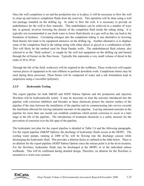
Once the well completion is set and the production tree is in place, it will be necessary to flow the wellto clean up and remove completion fluids from the reservoir. This operation will be done using a welltest package installed on the drilling rig. In order to flow the well, it is necessary to provide anunderbalance for the well to flow naturally. This underbalance can be achieved in a number of waysbut, in general, involves lowering the density of the completion fluid inside the tubing string. It istypically not recommended to use fresh water to lower fluid density in a gas well as this can lead to theformation of hydrates. Circulating nitrogen into the completion tubing is one alternative to loweringfluid density but tends to be equipment intensive on the drilling rig. Another alternative is to displacesome of the completion fluid in the tubing string with either diesel or glycol or a combination of both.This will likely be the method used for <strong>Deep</strong> <strong>Panuke</strong> wells. The underbalanced fluid column, alsoreferred to as the “fluid cushion”, is caught by the well test equipment on the drilling rig and burnedthrough the oil burner on the flare boom. Typically this represents a very small volume of diesel in theorder of 20 to 30 m³.Through the life of the field, workovers will be required in the wellbores. These workovers will requirevarious pieces of equipment to be sent offshore to perform downhole work. Completions brines may beused during these processes. These brines will be composed of water and a salt formulation kept insuspension using a viscosifier (polymer).2.3.9 Hydrostatic TestingThe export pipeline for both M&NP and SOEP Subsea Options and the production and injectionflowlines will be hydrostatically tested. It may be necessary to treat the seawater introduced into thepipeline with corrosion inhibitors and biocides as these chemicals protect the interior surface of thepipeline if the time between the installation of the pipeline and its commissioning into service exceedsthe timeframe allowed for leaving untreated seawater in the pipeline. Leaving untreated seawater in thepipeline for more than one month can establish conditions which permit corrosion to occur at a laterstage in the life of the pipeline. The introduction of treatment chemicals is a safety measure for theprevention of corrosion over the life span of the pipeline.The hydrostatic test plan for the export pipeline is detailed in Table 2.4 and the following paragraphs.For the export pipeline (M&NP Option), the discharge of hydrostatic fluids occurs at the MOPU. Thecooling water pumps, running at 2400 m 3 /hr, will be flowing into the discharge caisson whiledischarging the hydrostatic fluid. This provides a dilution factor as outlined in the table below. There isno dilution for the export pipeline (SOEP Subsea Option) since the release point is at the tie-in location.For the flowlines, hydrostatic fluids may be discharged at the MOPU or at the individual subseawellheads. This will be confirmed during detailed design. Therefore, no dilution for the flowlines isassumed as a worst case scenario.<strong>Deep</strong> <strong>Panuke</strong> Volume 4 (Environmental Assessment Report)• November 2006 2-29