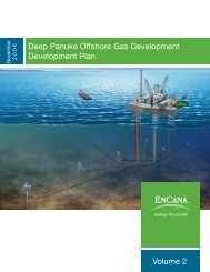
Deep Panuke Project Description - Encana
Deep Panuke Project Description - Encana
Deep Panuke Project Description - Encana

Create successful ePaper yourself
Turn your PDF publications into a flip-book with our unique Google optimized e-Paper software.
Once the surface section has been drilled and cased, blowout preventers are installed which canwithstand/holdback the reservoir pressures expected during the drilling process should a well controlincident occur. The primary method of well control is the hydrostatic pressure exerted by the column ofmud in the wellbore. The density of the mud that is used to drill the hole section is tailored to ensure thatthe ingress of wellbore hydrocarbons is prohibited. If the density of this fluid is too low a “kick” occursby which an amount of reservoir fluid enters the wellbore. As soon as this kick is detected, the well isshut in and monitored to determine the conditions surrounding the kick. The BOPs are used to shut inthe well. Once the well is shut in, the mud is circulated to bring the reservoir fluids to surface. Thehydrocarbons are vented or burnt at the flare in a controlled manner. The density of the mud is increasedthe appropriate amount and the drilling process may begin again.These blowout prevention safeguards are well-known operational procedures for which standardindustry practices are in place. EnCana’s Well Control Manual deals with these types of situations and isconstantly updated based on the most recent technological innovations. All personnel are trained on acontinuous basis and exercises and drills are routinely performed during operations on the drilling rig.During the production or injection life of a well, there are several safety measures in place to insure nouncontrolled release of hydrocarbons occur. The primary prevention mechanism within an offshorewellbore is the surface-controlled subsurface safety valve (SC-SSSV). The fail-close valve has a controlline to surface that is constantly pressured to keep the valve open. In the case of an accident, the ESDprocedure would have the valve close as soon as the hydraulic pressure is removed from the line. Allreservoir fluids are contained within the production or injection tree on top of the wellhead. This tree(series of fail-close surface valves) is connected to the tubing string within the wellbore that is used totransport the fluids to or from the reservoir. The SC-SSSV is an integral part of the tubing string usuallylocated at a depth below the seafloor. At the bottom of the tubing string, a production packer is placedbetween the tubing and casing to prevent migration of reservoir fluids in the annulus (space between thetubing and casing). This equipment provides a fit for purpose design conduit for the fluids to be removedfrom or injected into the reservoir.2.9.4 Flowline ProtectionThe flowlines design philosophy, in accordance with CNSOPB regulations, incorporates designs forinternal pressure containment, dropped objects protection, fatigue and spanning. The flowlines will beburied to avoid impacts from conventional mobile fishing gear and their locations will be charted.During the operational phase, inspections will be carried out as part of the Annual Survey to ensure thatthe pipeline integrity is maintained. Environmental and safety protection systems, such as emergencyshutdown (ESD) valves, will be provided on the flowlines.<strong>Deep</strong> <strong>Panuke</strong> Volume 4 (Environmental Assessment Report)• November 2006 2-59