Deep Panuke Project Description - Encana
Deep Panuke Project Description - Encana
Deep Panuke Project Description - Encana

You also want an ePaper? Increase the reach of your titles
YUMPU automatically turns print PDFs into web optimized ePapers that Google loves.
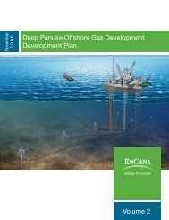
Use of a dedicated condensate pipeline to shore would necessitate the construction of onshorecondensate handling facilities such as storage tanks which would result in substantial capital costs. Thepipeline would have to be buried over its entire length (not easily accomplished over rocky areas) tomeet regulatory requirements and to protect it from possible damage from mobile fishing gear. Inaddition, the condensate pipeline would not be protected from clam dredges unless deeply buried. Thepotential environmental effects associated with rupture of such a condensate pipeline would also be aconcern. The quantities of condensate to be produced from the <strong>Deep</strong> <strong>Panuke</strong> field do not justify thecosts associated with a dedicated condensate pipeline. Thus, a dedicated condensate pipeline to shorewas deemed not economically feasible and was therefore rejected.The use of condensate as the primary fuel on the MOPU was also considered. Using condensate as fueleliminates the substantial capital and operating costs associated with a condensate pipeline to shore andassociated onshore handling facilities. The use of condensate as fuel on the platform conserves theresource by maximizing the quantity of natural gas exported to shore and by utilizing all components ofthe <strong>Deep</strong> <strong>Panuke</strong> resource.A seafloor subsea storage tank for holding a six-month volume of condensate offshore was alsoconsidered. While subsea storage tanks have been used at other offshore facilities, there is a high risk forpotential seafloor scour due to the relatively shallow water at the <strong>Deep</strong> <strong>Panuke</strong> site. That wouldnecessitate large quantities of rock protection around the tank. The prohibitive costs of such aninstallation resulted in this option being considered not economically feasible.2.10.2.10 Production Capacity AlternativesThe 2002 <strong>Project</strong> basis for production capacity was 11.3 x 10 6 m 3 /d [400 MMscfd]; however,alternatives for smaller facilities with peak production capacities of 8.5 x 10 6 m 3 /d [300 MMscfd] and5.7 x 10 6 m 3 /d [200 MMscfd] were also considered. Concepts were initially developed for jacketsupportedstructures for each alternative. It was found that the platform footprint, weight, and costreduced considerably when the production capacity was reduced from 11.3 x 10 6 m 3 /d [400 MMscfd] to8.5 x 10 6 m 3 /d [300 MMscfd]. However, the reduction in topsides weight (and cost) when theproduction capacity was further reduced to 5.7 x 10 6 m 3 /d [200 MMscfd] is marginal since the size ofprocessing equipment does not decrease in the same proportion as production capacity. The economicmodelling case at the 5.7 x 10 6 m 3 /d [200 MMscfd] production rates showed that the payout period wastoo lengthy at this rate, severely impacting the economics. It was concluded that the 8.5 x 10 6 m 3 /d [300MMscfd] plant size is more economically feasible for the Mean reservoir case and therefore wasselected for the plant production capacity rating.<strong>Deep</strong> <strong>Panuke</strong> Volume 4 (Environmental Assessment Report) · November 2006 2-78