introduction
introduction
introduction

You also want an ePaper? Increase the reach of your titles
YUMPU automatically turns print PDFs into web optimized ePapers that Google loves.
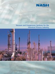
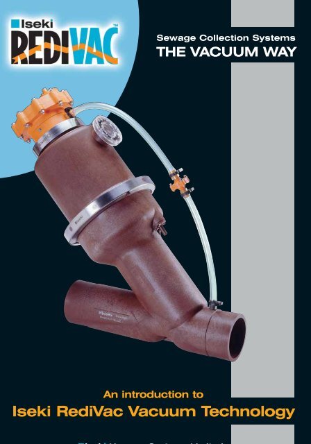
Sewage Collection Systems<br />
THE VACUUM WAY<br />
An <strong>introduction</strong> to<br />
Iseki RediVac Vacuum Technology<br />
Vacuum Systems Limited
This document is intended as a source of information for engineers, developers, contractors and clients interested in<br />
learning about the vacuum sewage collection systems designed by Iseki Vacuum Systems Ltd. The information herein is<br />
for reference purposes only and readers should not plan or design a vacuum sewerage system based upon the<br />
information contained within this publication without prior consultation with Iseki Vacuum Systems Limited.<br />
Iseki Vacuum Systems Limited have a continuous research and development programme for their vacuum sewage<br />
collection systems and reserve the right to change the equipment, material specifications and design parameters of their<br />
vacuum systems without notice.<br />
For further information on Iseki’s vacuum technology please use the contact details given below:<br />
Iseki Vacuum Systems Limited<br />
High March<br />
Daventry<br />
Northamptonshire<br />
NN11 4QE<br />
United Kingdom<br />
Tel : + 44 (0)1327 878777<br />
Fax : + 44 (0)1327 315232<br />
Website: www.iseki-vacuum.com<br />
E-mail : sales@iseki-vacuum.com<br />
© September 2004<br />
2
CONTENTS<br />
Section<br />
Page<br />
1 Introduction 5<br />
2 The History of Vacuum Technology 7<br />
3 Operation of a Vacuum Sewerage System 9<br />
4 Advantages of Vacuum Sewerage Systems 15<br />
5 Applications of Vacuum Technology 17<br />
6 A Selection of Iseki RediVac World-wide Projects 18<br />
7 Iseki RediVac Materials and Equipment 21<br />
The Interface Valve Test 21<br />
Iseki RediVac Interface Valve Monitoring System 25<br />
‘Intelligent’ Monitoring System 26<br />
Sewage High Level Alarm System 26<br />
Valve Monitoring Principles 27<br />
Typical Vacuum Station Equipment 28<br />
8 Iseki RediVac’s Scope of Services 30<br />
9 Frequently Asked Questions 31<br />
Appendix 37<br />
Figure 5<br />
Figure 6<br />
Figure 7<br />
Figure 8<br />
Typical Concrete Valve Chamber<br />
GRP Collection Chamber<br />
Typical Sewer Profile and Invert Lift Detail<br />
Typical Vacuum Sewer Profiles<br />
3
SECTION 1<br />
INTRODUCTION<br />
Iseki Vacuum Systems Limited (trading as Iseki RediVac) is based in Daventry in the United<br />
Kingdom from where it markets its vacuum technology world-wide through local representatives<br />
and distributors. This UK office provides the expertise required for developing and supporting this<br />
technology throughout its world-wide markets.<br />
This engineering expertise has been developed over the past 10 years and during this time Iseki<br />
RediVac’s engineers have gained a wide understanding of the potential uses of their vacuum<br />
systems and have applied this experience to many different applications.<br />
With a broad staff base covering many disciplines, Iseki RediVac is able to offer clients services<br />
which range from initial project appraisals through to commissioning and handover of their<br />
vacuum systems.<br />
Iseki RediVac believes strongly in customer support and is able to offer technical advice and<br />
assistance to local operators of their systems and, if required, on-site supervision from one of<br />
their own field engineers.<br />
To supplement this, Iseki RediVac has a network of service centres across the world providing<br />
local support to system operators.<br />
The key item of equipment within any vacuum system is the vacuum interface valve housed<br />
within the collection chambers. Iseki RediVac’s interface valve has been in use for more than 10<br />
years and during that time has seen a number of improvements to further enhance its<br />
performance and reliability.<br />
These performance capabilities were demonstrated through tests which required the valves to<br />
operate in excess of 250,000 times which is the equivalent of more than 15 years of normal<br />
operation.<br />
The successful completion of these tests resulted in Iseki RediVac’s valve complying with the<br />
British Standards Institution code for vacuum sewerage systems BS EN 1091 : 1997.<br />
With its reputation for designing, installing and commissioning its vacuum systems as well as<br />
manufacturing products with proven reliability, Iseki RediVac is a world leader in the field of<br />
vacuum sewage collection systems.<br />
5
SECTION 2<br />
THE HISTORY OF VACUUM<br />
TECHNOLOGY<br />
The principle of using vacuum pressure to collect waste water and other liquids has been used<br />
since the 1860’s and many pioneers were involved in the development of the technology, the<br />
most successful of which was Mr. Charles T. Liernur.<br />
As can be seen from Figure 1 on the following page, Mr. Liernur’s system was used to collect<br />
sewage from domestic houses and consisted of an underground storage tank into which the<br />
effluent arrived via iron pipes under gravity flow.<br />
The pipes themselves were connected to special toilets within each property and each night a<br />
vacuum pressure was applied to the underground tank causing sewage to be removed from the<br />
toilets and collected in the tank.<br />
A mobile tanker was then used to remove the sewage from the storage tank by use of vacuum<br />
pressure and the sewage was then put into barrels to be later sold to local farmers as fertiliser.<br />
The next developments in vacuum technology were made in the 1920’s by Mr. Henri Gandillon<br />
from France.<br />
Both sewage and surface water collected from up to 4 houses flowed by gravity into a chamber<br />
located within the road. An outlet pipe within this chamber was connected to a main sewer pipe<br />
which in turn was connected to a vacuum station.<br />
As sewage entered the chamber, a ball sealing the outlet pipe would float and expose the open<br />
end of the pipe. A vacuum pressure was then applied to this pipe by manually opening an<br />
isolation valve within the main sewer pipe, thereby causing the sewage to be sucked from the<br />
chamber.<br />
There are no records of further developments in vacuum technology until the 1950’s when<br />
Mr. Joel Liljendhal of Sweden perfected the vacuum toilet first developed by Mr. Liernur.<br />
7
Figure 1<br />
Early Vacuum Sewage Collection Systems<br />
8
SECTION 3<br />
OPERATION OF A<br />
VACUUM SEWERAGE SYSTEM<br />
Vacuum systems can be used to collect a variety of fluids, however they are most commonly used<br />
to collect sewage from within domestic housing developments.<br />
Figure 2 below indicates the typical layout of such a system, the three main components of which are<br />
as follows :-<br />
Valve Chambers / Sumps<br />
These chambers serve two purposes:<br />
1. To collect the effluent discharged from the connecting properties.<br />
2. To allow the collected sewage to enter the sewer network via the Iseki RediVac interface valve.<br />
The Vacuum Sewers<br />
These form the pipe network through which vacuum pressure is transferred to the Iseki RediVac interface<br />
valves within the collection chambers and along which the effluent is transported to the vacuum station.<br />
The Collection / Vacuum Station<br />
This is the heart of the system and is where the vacuum pressure is generated for the whole sewerage<br />
network which allows the effluent to be collected and forwarded to the sewage treatment plant.<br />
COLLECTION STATION<br />
GRAVITY SEWER<br />
COLLECTION SUMP<br />
VACUUM SEWER<br />
Figure 2 Typical Vacuum Sewerage System Layout<br />
9
Taking these elements in turn, we begin with the valve chambers and the vacuum interface<br />
valves installed therein.<br />
1. Valve Chambers / Sumps<br />
ISEKI INTERFACE<br />
VALVE<br />
SUCTION PIPE<br />
SEWAGE ENTERING<br />
WET SUMP<br />
Figure 3.1<br />
FLEXIBLE<br />
TUBING<br />
VALVE CONTROLLER<br />
SEWER PIPE UNDER<br />
VACUUM PRESSURE<br />
AIR PRESSURE WITHIN<br />
SENSOR PIPE INCREASES<br />
Figure 3.2<br />
10
ISEKI INTERFACE<br />
VALVE OPEN<br />
SEWAGE ENTERING<br />
SUCTION PIPE<br />
Figure 3.3<br />
AIR ENTERING SEWER<br />
AFTER SEWAGE<br />
Figure 3.4<br />
11
Sewage arrives via normal gravity pipes at the lower section, or wet sump, of the collection<br />
chamber just like a manhole in a conventional gravity system (see Figure 3.1).<br />
As the level of the effluent within the wet sump rises, air is trapped in a pipe called a ‘sensor<br />
pipe’, the pressure of which increases as the effluent level continues to rise (see Figure 3.2).<br />
This increase in air pressure is subsequently transferred via flexible tubing to the top section of<br />
the interface valve which is known as the ‘controller’.<br />
Eventually this pressure becomes great enough to operate a switch within the controller which<br />
then allows vacuum pressure to be transferred to the main body of the valve and cause it to<br />
open.<br />
With the valve in the open position, air at atmospheric pressure acting on the surface of the liquid<br />
within the wet sump then forces the sewage into the ‘suction pipe’, past the interface valve and<br />
onward into the sewer pipe network (see Figure 3.3).<br />
Once all of the sewage has been removed from the wet sump, the valve remains open for a short<br />
period of time to allow air at atmospheric pressure to enter the sewer pipe network (see<br />
Figure 3.4).<br />
The valve then closes under the action of a spring to complete one cycle.<br />
2. The Vacuum Sewers<br />
The sewage is now within the second element of the system, namely the vacuum sewers and<br />
typical profiles of these sewers can be seen in Figure 8 in the appendix.<br />
The diameter of the pipes is between 90mm to 250mm and they are normally constructed from<br />
High Density Polyethylene (HDPE) jointed using electro-fusion welding collars.<br />
It is the air admitted through the interface valve that is the means by which the sewage travels<br />
along these sewer pipes.<br />
Initially the sewage travels at velocities of up to 6m/s as a foaming mixture of liquid and air. The<br />
velocity gradually reduces as the mixture moves along the sewer and the air eventually overtakes<br />
the liquid and continues onward towards the vacuum station.<br />
At this point the vacuum sewers act exactly like conventional gravity pipes and the sewage travels<br />
within them by normal gravity flow.<br />
Eventually the sewage comes to rest at low points within the sewers called ‘invert lifts’ and<br />
remains stationary. The next time an interface valve opens and allows air to enter the sewer<br />
network, this sewage is lifted from the low point and transported onward towards the vacuum<br />
station (see Figures 3.5 to 3.7).<br />
12
Figure 3.5<br />
Figure 3.6<br />
Figure 3.7<br />
13
3. The Collection / Vacuum Station<br />
Finally, the sewage reaches the vacuum station, which is the third element of the system.<br />
The main items of equipment within the vacuum station are vacuum pumps, a collection vessel,<br />
sewage discharge pumps and an electrical control panel (refer to Figure 4).<br />
The vacuum pumps are connected to the collection vessel via pipework and they create the<br />
vacuum pressure within both the vessel and the connecting vacuum sewers.<br />
The arriving sewage is initially stored in the collection vessel which acts as the wet sump normally<br />
found within a conventional gravity pumping station.<br />
Rising sewage levels within this collection vessel are detected by level probes which initiate the<br />
operation of sewage discharge pumps connected via pipework to the vessel.<br />
These pumps remove the collected sewage from within the vessel and forward it to the local<br />
sewage treatment plant or nearby main sewer.<br />
VACUUM PUMP<br />
EXHAUST PIPEWORK<br />
VACUUM<br />
RESERVOIR<br />
VESSEL<br />
VACUUM SEWERS<br />
SEWAGE<br />
COLLECTION<br />
VESSEL<br />
SEWAGE PUMPS<br />
SLIDING VANE<br />
VACUUM PUMPS<br />
ELECTRICAL<br />
CONTROL PANEL<br />
VACUUM GAUGES<br />
DISCHARGE<br />
PIPEWORK<br />
CHART<br />
RECORDER<br />
VALVE<br />
MONITORING DISPLAY<br />
PUMPING MAIN<br />
Figure 4 Typical Vacuum Station<br />
14
SECTION 4<br />
ADVANTAGES OF VACUUM<br />
SEWERAGE SYSTEMS<br />
The decision to use a vacuum sewage collection system instead of a conventional gravity<br />
system offers three main benefits :<br />
1. Design flexibility<br />
2. Capital cost savings<br />
3. Operational cost savings<br />
1. Design Flexibility<br />
The inherent versatility of vacuum systems gives clients flexibility in their approach to solving their<br />
fluid collection problems.<br />
Below are just a few of the benefits which can be gained through the flexibility available when<br />
designing vacuum fluid collection systems:<br />
1. Without restrictions on the line or level of vacuum sewers, the pipes can be installed as<br />
required to suit the site conditions.<br />
2. Lightweight small diameter sewer pipes allow ease of installation where access is<br />
restricted.<br />
3. The self-cleansing nature of vacuum sewers removes the requirement for rodding eyes<br />
and washout chambers.<br />
4. With effluent being conveyed by vacuum pressure rather than gravity flow, sewage can<br />
be transported uphill.<br />
5. Due to 4. above, the vacuum stations need not be located at the low lying areas within<br />
a development. This flexibility of station location can provide significant benefits if land<br />
availability is restricted or environmental constraints are imposed within the<br />
development.<br />
6. Obstacles can be easily negotiated by re-routing the vacuum sewers over, under or<br />
around obstructions.<br />
15
2. Capital Cost Savings<br />
Capital cost savings in excess of 40% are possible through the construction of vacuum sewage<br />
collection systems due to the following:<br />
1. Trench excavations required for constructing the sewer pipe network are narrow and<br />
shallow (maximum sewer depths are 1.5 metres).<br />
2. The speed of construction is greatly increased due to (1) above.<br />
3. High water tables can be avoided due to shallow sewer pipes.<br />
4. No requirement for piled sewer foundations through the use of the lightweight<br />
polyethylene pipework from which the sewers are constructed.<br />
5. No requirement for manholes at sewer direction changes therefore manhole numbers<br />
are reduced.<br />
6. Vacuum collection chambers are installed at a maximum depth of 2 metres throughout<br />
the sewer network.<br />
7. Reduced depth of vacuum station foundations (typical depth 1 metre).<br />
8. Only one vacuum station is required for a single development whereas conventional<br />
gravity systems usually require several pumping stations.<br />
9. Additional land available within development due to (8) above.<br />
3. Operational Cost Savings<br />
Operational cost savings can be reduced by up to 30% due to the following:<br />
1. Vacuum sewers are self-cleansing therefore there is no requirement to clean or remove<br />
sediments from within the vacuum sewers.<br />
2. There is no requirement for screens at the vacuum station and therefore weekly visits<br />
to the station are not needed.<br />
3. Only one vacuum station is needed to be maintained whereas a gravity system will<br />
have several pumping stations requiring regular attendance.<br />
4. There is no infiltration of ground water into the vacuum sewers and therefore pump<br />
sizes and subsequently electrical power consumption are significantly reduced.<br />
5. The cost of treatment is greatly reduced due to 4. above.<br />
6. The integrity of the vacuum sewers is maintained throughout the lifetime of the system<br />
due to the robust material from which the sewers are constructed (polyethylene).<br />
7. No need for repairs arising from settlement of pipework due to 6. above.<br />
16
SECTION 5<br />
APPLICATIONS OF<br />
VACUUM TECHNOLOGY<br />
Vacuum fluid collection systems can be employed in a<br />
wide range of situations and typical applications of this<br />
versatile and environmentally friendly technology are<br />
indicated below:<br />
Rural community main sewerage<br />
Roof drainage<br />
Camp and caravan sites<br />
New housing developments<br />
Old towns with narrow streets<br />
Hospital effluent collection<br />
Shopping centres with difficult or confined areas<br />
Replacement of conventional gravity systems<br />
Petro-chemical industry<br />
Factory sewerage<br />
Arctic communities<br />
Leachate from landfills<br />
Spillage around industrial storage tanks<br />
River, lakeside and coastal communities<br />
Quayside re-developments<br />
Ship to shore sewage collection<br />
For examples of the above applications please contact<br />
Iseki RediVac or their local representative.<br />
17
SECTION 6<br />
A SELECTION OF ISEKI<br />
Client Location Country Year<br />
Anglian Water Walpole St. Peter Extension UK 2004<br />
Southern Water Bromley Green Upgrade UK 2004<br />
Southern Water Yalding Upgrade UK 2004<br />
Tisice Village Czech Czech Republic 2004<br />
Philcor Pty Sanctuary Lakes Extension 2 Australia 2004<br />
ISA Polska Zoo Rajeckie Pieńki Poland 2004<br />
ISA Polska Zoo Czermin Poland 2004<br />
ISA Polska Zoo Cerekiew Poland 2004<br />
ISA Polska Zoo L¾cana Phase 2 Poland 2004<br />
ISA Polska Zoo Ceglów Poland 2004<br />
ISA Polska Zoo Michów phase 2 Poland 2004<br />
Rapidan Service Authority Lake of the Woods Extensions USA 2004<br />
Inárcs Operating Co Inárcs Phase 2 Hungary 2004<br />
Hidepito Röszke Phase 2 Hungary 2004<br />
VITEP Szigetujfalu Hungary 2004<br />
Envitech Bandar Botanic Parcel 2 Malaysia 2004<br />
Hidepito Domaszek Phase 2 Hungary 2003<br />
U.V.I.E.P KFT Korostarcsa Phase 2 Hungary 2003<br />
Philcor Pty Sanctuary Lakes Extension 1 Australia 2003<br />
ISA Polska Zoo L¾cana Poland 2003<br />
ISA Polska Zoo Wiazownica Poland 2003<br />
ISA Polska Zoo Michów Poland 2003<br />
ISA Polska Zoo Nadarzyn Phase 2 Poland 2003<br />
ISA Polska Zoo Wacyn, Briel Poland 2003<br />
ISA Polska Zoo Abramàw Poland 2003<br />
Develop Whitwell Whitwell UK 2003<br />
Vegyesipari Szolgaltato Pilis Phase 2 Hungary 2003<br />
Deacon Caravan Park Benone Phase 2 Northern Ireland 2003<br />
Yorkshire Water Rosedale Abbey Refurbishment UK 2003<br />
Anglian Water New Bollingbrook Upgrade UK 2003<br />
Sharjah University American University Phase 6 UAE 2003<br />
Anglian Water West Dale Refurbishment UK 2003<br />
Sharjah University Etilsalat College UAE 2003<br />
Centroprojekt CSN Steel Works Brazil 2003<br />
Severn Trent Arlingham UK 2003<br />
Envitech Botanical Gardens Phase 2 Malaysia 2003<br />
Binder Holton Hall UK 2002<br />
Severn Trent Four Crosses Service UK 2002<br />
Anglian Water Gorefield UK 2002<br />
Envitech Bandar Botanic Parcel 1 Malaysia 2002<br />
Anglian Water Maltby-le-Marsh Upgrade UK 2002<br />
Anglian Water Holton & Raydon Upgrade UK 2002<br />
Infrastart Kft Monori Erd. Hungary 2002<br />
Anglian Water Holton Hall Business Park UK 2002<br />
18
REDIVAC WORLD-WIDE PROJECTS<br />
Client Location Country Year<br />
Hidepito Abony Hungary 2002<br />
Vakond Toszeg Hungary 2002<br />
ISA Polska Nadrzyn Poland 2002<br />
Anglian Water Tydd St Giles UK 2002<br />
ISA Polska Zakrzew Poland 2002<br />
Innoterv Rt Szigetbecse Hungary 2001<br />
Infrastart Kft Monor Hungary 2001<br />
Anglian Water Orby refurb U.K. 2001<br />
infrastartKft Gomba Hungary 2001<br />
Innoterv Rt Dömsöd Hungary 2001<br />
Severn Trent Four Crosses - Station Upgrade U.K. 2001<br />
Infrastart Kft Csévharaszt Hungary 2001-02<br />
Innoterv Rt Makád Hungary 2001<br />
Innoterv Rt Ráckeve Hungary 2001<br />
NOOSA Queensland Australia 2001<br />
Envitech Pulau Indah Section 10 Malaysia 2001<br />
Vakond Kft Tiszavárkony Hungary 2001<br />
Vakond Kft Tiszajen Hungary 2001<br />
Vakond Kft Tószeg Hungary 2001<br />
Infrastart Kft Vasad Hungary 2001-02<br />
Vakond Kft Vezseny Hungary 2001<br />
ISA Polska Lubwin Poland 2001<br />
Thargomindah Village New South Wales Australia 2001<br />
Innoterv Rt Orgovány Hungary 2000<br />
Sharjah University Phase 4 UAE 2000<br />
Innoterv Rt Izsák Hungary 2000<br />
Coomera Marine Precinct Brisbane Australia 2000<br />
Toowoombah Brisbane Australia 2000<br />
Philcor Pty Minamurra, New South Wales Australia 2000<br />
Plantation Florida USA 2000<br />
Philcor Pty Sanctuary Lakes 7&8 Melbourne Australia 2000<br />
North Slope Borough, Alaska Nuitsut village, Package Vacuum Stn USA 2000<br />
Philcor Pty Falcon, Perth Australia 2000<br />
Philcor Pty Sydney Harbour Australia 1999<br />
Hepburn & Thorpe Coomera Village Australia 1999<br />
Innoterv Kft Ágasegyháza Hungary 1999-00<br />
Dept of Environment Benone Extension Ireland 1999<br />
Philcor Pty Water Fall Gully Australia 1999<br />
Sharjah Municipality Police Academy - Sharjah University UAE 1999<br />
North Slope Borough, Alaska Aqusik Village, Package Vacuum Stn USA 1999<br />
Thames Water Services Wraysbury Village - Windsor UK 1999<br />
City of Virginia Beach Salem Road USA 1999<br />
City of Virginia Beach Alanton Road Phase 2 USA 1999<br />
Thames Water Services Hamm Court - refurbishment London UK 1999<br />
19
SECTION 7<br />
ISEKI REDIVAC MATERIALS AND<br />
EQUIPMENT<br />
THE INTERFACE VALVE TEST<br />
In order to satisfy the requirements set out in the British Standard document BS EN 1091:1997<br />
entitled ‘Vacuum Sewerage Systems Outside Buildings’, Iseki RediVac tested their interface<br />
valve as described in Section 7, paragraph 7.1.2 and Annex A paragraphs A.2, A.3 and A.4 of the<br />
document which reads as follows:<br />
A.2 The interface unit shall have a proven ability to undertake a specified number of<br />
cycles without attention other than the manufacturer’s recommended maintenance<br />
and still function effectively. The specified number of cycles shall be the greater of<br />
a) The number of cycles needed to evacuate 3,000m³; or<br />
b) 250,000 cycles.<br />
Iseki RediVac carried out the test based on part (b) of the above section.<br />
A.3 The test requires selected foreign matter to be cycled through the interface valve.<br />
Corks, plastic bags, sanitary towels and disposable nappies and other foreign matter<br />
are water logged and feed into the collection chamber piece by piece over ten<br />
cycles in random order. All foreign matter is to be sucked through the test rig without<br />
any blockages.<br />
A.4 The vacuum shall be released and the collection chamber sump shall be filled with<br />
water sufficient to cover the top of the interface valve body by 300mm. The breather<br />
tube shall not be submerged. After remaining submerged for 24 hours the vacuum<br />
shall be restored and the interface valve mechanism cycled 20 times. The test shall<br />
be undertaken 3 times.<br />
A registered quality lead assessor named John Edward & Associates witnessed the testing of<br />
Iseki RediVac’s interface valve and upon completing the tests as specified above, the valve was<br />
certified as shown on page 24.<br />
21
Tested to BS EN 1091:1977<br />
Interface valve performed more than 250,000 cycles<br />
22
JOHN EDWARDS & ASSOCIATES<br />
ENGINEERING CONSULTANTS<br />
19 ASHLEIGH ROAD, SOLIHULL, WEST MIDLANDS B91 1AE.<br />
TELEPHONE: +44(0)121 705 1228 FAX: +44(0)121 705 4890<br />
E-mail: emas.john@dial.pipex.com<br />
15th March 1999<br />
Testing of Iseki 90mm Vacuum Interface Valves<br />
to BS EN 1091 : 1977<br />
This is to confirm that I have witnessed the testing of a 90mm Iseki Vacuum<br />
Interface valve under simulated working conditions to the requirements of BS EN<br />
1091 : 1997, in particular the requirements of para 7.1.2. The valve completed<br />
250,000 cycles without maintenance and was still working completely<br />
satisfactorily when the test was terminated. Subsequent strip down of the valve<br />
revealed negligible wear in all the moving parts.<br />
John Edwards<br />
Chartered Engineer<br />
Registered Quality Lead Assessor<br />
PRINCIPAL J. H. EDWARDS M.B.E., B.A., C.ENG., F.I.MECH.E., M.I.MGT., M.I.Q.A.<br />
23
ENGINEERING CONSULTANTS<br />
AS LAID DOWN IN PARA.7.1.2 AND ANNEX A<br />
JOHN EDWARDS & ASSOCIATES<br />
19 ASHLEIGH ROAD, SOLIHULL, WEST MIDLANDS B91 1AE.<br />
TELEPHONE: +44(0)121 705 1228 FAX: +44(0)121 705 4890<br />
E-mail: emas.john@dial.pipex.com<br />
THIS IS TO CERTIFY THAT<br />
ISEKI 90MM VACUUM INTERFACE VALVES<br />
FULLY SATISFY<br />
THE TESTING AND VERIFICATION CONDITIONS<br />
(NORMATIVE) PARAS A.2, A.3 AND A.4<br />
OF BS EN 1091:1997<br />
PRINCIPAL J. H. EDWARDS M.B.E., B.A., C.ENG., F.I.MECH.E., M.I.MGT., M.I.Q.A.<br />
24
ISEKI REDIVAC INTERFACE<br />
VALVE MONITORING SYSTEM<br />
The Iseki RediVac Interface Valve Monitoring System detects the status of each interface valve<br />
on a vacuum system and indicates whether the valve is open or closed on a display panel<br />
located within the vacuum station.<br />
This is an essential operational tool as it pinpoints valves which have failed to close properly and<br />
are therefore causing a loss of pressure within the vacuum system. A loss of pressure is<br />
generally caused by a foreign object preventing the plunger inside an interface valve from<br />
properly sealing the sewer pipe and it is at this stage that the monitoring system becomes<br />
invaluable in locating the troublesome valve.<br />
The method of operation is simple. A switch attached to the body of each interface valve detects<br />
whether the valve is open or closed and relays this information to the vacuum station via a signal<br />
cable installed alongside the vacuum sewer pipes.<br />
Within the vacuum station a Light Emitting Diode (LED) display then indicates the open and<br />
closed status of each valve, with an LED being illuminated when a valve is open.<br />
Examination of the display panel will indicate which interface valve has failed to close as each<br />
valve has a unique identity code. A visit to the valve chamber housing the valve will then allow the<br />
problem to be rectified.<br />
When pressure losses are occurring on the<br />
vacuum system, the speed at which problem<br />
valves can be identified is greatly increased using<br />
this system. This in turn significantly reduces the<br />
time required on site by maintenance crews and<br />
allows the vacuum system to be quickly returned<br />
to normal operation.<br />
Connection of collection chambers to valve monitoring system<br />
Laying of valve monitoring cable within sewer trench<br />
25
‘INTELLIGENT’ MONITORING SYSTEM<br />
Fundamental to the system is a sensor on each Iseki Redivac interface valve which relays a<br />
signal to a central monitoring computer whenever a valve operates. The monitoring computer<br />
will constantly display the current situation within the collection system indicating which valves are<br />
in operation at any one time. This replaces the wall mounted display panel with LEDs showing<br />
the open or closed status of each valve.<br />
The benefits of the new system are many. All<br />
information is stored for a minimum of 28 days<br />
allowing the operator to evaluate the efficiency of<br />
all the interface valves. This enables the operator<br />
to quickly identify the valve’s frequency of<br />
operation and identify any unusual patterns. Any<br />
failure in the system itself or unusually heavy flow<br />
rates are easily identified allowing the operators to<br />
resolve the situation quickly and efficiently.<br />
Iseki RediVac’s new management information<br />
system will bring considerable cost efficiencies in<br />
operation as well as identifying maintenance<br />
scheduling for each interface valve. This exciting<br />
development will allow accurate targeting of<br />
maintenance and enhance the overall<br />
performance by providing an instant wide-angled<br />
view of the entire installation.<br />
‘Intelligent’ Monitoring System<br />
SEWAGE HIGH LEVEL ALARM SYSTEM<br />
Iseki RediVac have devised and implemented a system for monitoring the level of sewage in the<br />
collection pits around the sewer network. An alarm is raised to alert the operations staff of an<br />
overflow in a particular vacuum chamber identified by the LED display panel within the vacuum<br />
station. Furthermore ‘real time data’ can be collated and stored to provide benefits, for example;<br />
trending on location, frequency of occurrence, response of maintenance crews and their<br />
efficiency in dealing with the problem.<br />
System Components<br />
An armoured twin pair electrical cable is<br />
provided and laid within the vacuum sewer<br />
pipe trench. This has the ability to link all the<br />
vacuum chambers, via the cable, with<br />
equipment located within the vacuum<br />
station.<br />
A high level float switch is placed within the<br />
sump and calibrated to activate a switch at<br />
a predetermined level before the sump<br />
reaches flood level.<br />
Within the vacuum station is an LED display<br />
panel with one LED for each vacuum<br />
chamber. In the event of flood conditions<br />
being detected the corresponding LED<br />
within the panel will illuminate.<br />
Valve chamber fitted with high level warning equipment.<br />
26
VALVE MONITORING PRINCIPLES<br />
Data Processing and Benefits<br />
As all sumps are linked together in a loop<br />
back to the station and as each sump has<br />
a dedicated signal the receiver is able to<br />
monitor if any particular switch has been<br />
activated by the high level switch.<br />
Data can then be processed and<br />
forwarded in the form of an alarm to a<br />
central control room where it can be<br />
specifically identified by the operations<br />
personnel.<br />
Appropriate actions can then be taken,<br />
such as calling out the maintenance crew,<br />
or putting the alarm on standby to allow a<br />
recovery period to bring the sewage level<br />
down to an acceptable level.<br />
Valve monitoring transmitter installed on Iseki RediVac Interface Valve<br />
By installing further software, all such<br />
incidents for each sump can be<br />
stored for extended periods and data<br />
provided for historic analysis.<br />
The actions of maintenance crews to<br />
such a call out can be recorded,<br />
such as their efficiency and<br />
attendance on site.<br />
Software programmes can be<br />
installed to provide various levels of<br />
information and statistics to suit the<br />
individual client’s requirements.<br />
All results can be presented in data<br />
or graphic format and easily stored<br />
for historic purposes.<br />
The technology usually operates in<br />
parallel with the ISEKI REDIVAC<br />
VALVE MONITORING SYSTEM.<br />
The system is installed during the<br />
main construction period which has<br />
the advantage of minimising<br />
installation costs.<br />
Valve monitoring display panel housed within vacuum station<br />
By incorporating this equipment in a<br />
vacuum sewerage system the<br />
frequency of routine site attendances<br />
can be greatly reduced.<br />
27
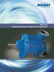
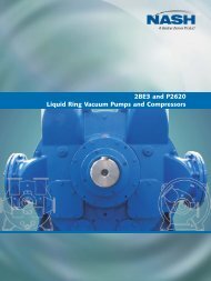
TYPICAL VACUUM STATION EQUIPMENT<br />
Rotary vane, single stage oil-sealed<br />
vacuum pumps<br />
Dry well, centrifugal screw sewage discharge pumps<br />
28
Motor Control Centre complete with integral PLC and valve<br />
monitoring console<br />
Steel sewage collection vessel<br />
Sensor probes and switches<br />
Biological Filtration Unit<br />
29
SECTION 8<br />
ISEKI REDIVAC’S SCOPE OF SERVICES<br />
Below are details of the services which Iseki RediVac are able to offer to clients considering using<br />
vacuum sewerage technology.<br />
1. Vacuum System Cost Estimates<br />
Initially clients generally wish to compare the capital cost of installing a vacuum system against that of<br />
using a more conventional sewage collection system.<br />
To assist with this, Iseki RediVac will examine layout plans of the proposed development and produce<br />
a conceptual design of a vacuum sewerage system.<br />
From this, specific information such as the number of collection chambers, sewer pipe sizes and<br />
vacuum station dimensions can be established and a budget cost estimate produced for the client to<br />
examine.<br />
2. Detailed Engineering Design and Construction<br />
If the client decides to proceed with the vacuum option, Iseki RediVac can produce detailed designs<br />
of their vacuum systems including engineering drawings and specifications which can then be offered<br />
to civil engineering contractors for pricing.<br />
Alternatively, Iseki RediVac is able to offer TURNKEY or even BOOT packages to clients for the design<br />
and construction of their vacuum systems.<br />
3. System Commissioning and Training<br />
Upon completion of the vacuum system, Iseki RediVac’s engineers will perform a full commissioning<br />
of the system in readiness for on-line operation.<br />
As part of this service, Iseki RediVac will also introduce the client’s maintenance staff to vacuum<br />
technology and carry out training in the day to day operation and maintenance of the system.<br />
4. Servicing of Existing Vacuum Systems<br />
Iseki RediVac can offer maintenance and service packages ranging from simple appraisals through to<br />
full refurbishment of clients’ vacuum systems.<br />
With a number of diagnostic tools available to Iseki RediVac’s engineers, a survey of an existing<br />
vacuum system can establish information such as real time vacuum pressure levels, pump operations,<br />
actual sewage flows and interface valve activity.<br />
With this information to hand, Iseki RediVac’s engineers can advise operating staff on the performance<br />
levels of their vacuum systems and offer solutions to help maximise operational efficiencies.<br />
30
SECTION 9<br />
FREQUENTLY ASKED QUESTIONS<br />
This section raises some of the most frequently asked questions that are asked of Iseki RediVac’s<br />
engineers. They have been divided into broad categories to assist the reader in identifying<br />
questions of a particular nature.<br />
One such question is ‘In what situations may a vacuum system be used?’<br />
Vacuum systems have been used in a great variety of locations and operational requirements. In<br />
the UK many systems are used to provide first time sewerage schemes for communities that, due<br />
perhaps to poor ground conditions or difficult topography, are uneconomical to sewer by<br />
conventional means.<br />
Additionally, the flexibility of the system has led to its use in many different applications such as<br />
Wimbledon Tennis Club, to drain water from the roofs at Centre Court and No. 1 Court, and in<br />
Malaysia to sewer communities of 20,000 inhabitants.<br />
Attached is a list of vacuum systems installed over the last fifteen years or so, which will give an<br />
indication of the number and variety of applications.<br />
It is worth noting that internationally recognised consultants such as Halcrow, Parsons, Watsons,<br />
Acers, Dames and Moore, Babtie, WSAtkins, Khatib & Alami, Haswell and many others have<br />
worked with the Iseki RediVac vacuum technology and are actively studying further applications.<br />
Construction<br />
1. What size of trench is required for a vacuum sewer?<br />
In general, the width of the trench will be dictated by the construction method employed. For<br />
example, if a trenching machine is available and the ground conditions allow, the trench may be<br />
only 100mm wider than the pipe diameter. Back hole excavated trenches are typically 450mm in<br />
width.<br />
It would, of course, be necessary to increase the width when using a trenching machine where<br />
man entry is required to make joints.<br />
2. What depth of trench is needed?<br />
Usual practice demands the pipe cover to be approximately 900mm under normal traffic load<br />
conditions (to withstand wheel loadings), and about 500mm to 700mm under walkways etc.<br />
3. What bed and surround material is used?<br />
This will be dependent upon the local codes for the pipe material used. Typically in the UK, for<br />
example, a bed of 100mm of granular fill with a cover to the crown of the pipe of a further 150mm<br />
of granular material. However, the vacuum main does not require any different bedding to be<br />
used than for a water main in a similar pipe material.<br />
4. Is the use of marker/tracer tapes recommended with vacuum sewers?<br />
Yes, this is good practice.<br />
31
Interface Valve<br />
1. What is the life of a vacuum interface valve?<br />
The Iseki RediVac interface valve can be expected to last in excess of 25 years. Approximately<br />
every seven years we recommend that bearings and rubber diaphragms are replaced.<br />
2. Of what material is the interface valve made, where is it manufactured and are spare parts<br />
readily available?<br />
The valve is made of glass filled polypropylene with all metal components being of 316(A4)<br />
stainless steel. The Iseki RediVac interface valve is manufactured by Iseki Vacuum Systems at<br />
their Daventry factory in the UK. Spare parts are also available at Daventry or from one of Iseki<br />
RediVac’s many official distributors or service centres situated throughout the world. All spare<br />
parts are ex-stock.<br />
3. Are any specials tools required to service the valve?<br />
No, a standard tool kit used by a maintenance fitter will contain all that is necessary to carry out a<br />
service of the Iseki RediVac interface valve.<br />
4. How many properties may be connected to a single interface valve?<br />
This is not a question that can be answered with a single definitive figure. At the design stage<br />
many factors are taken into consideration such as the size of the main onto which the valve is<br />
connected, the position of the valve within the overall network and the number and configuration<br />
of adjacent valves.<br />
In general, it is advantageous to keep the number of properties per valve higher rather than lower,<br />
as the more frequent firing of the valve will optimise the transportation of the sewage in the<br />
mains. The less sewage that remains in the sump, the less likelihood of septicity setting in before<br />
sewage reaches the treatment plant. The Iseki RediVac valve offers considerable advantages as it<br />
has a variable timer on the air cycle of the valve opening, which offers more design and<br />
operational flexibility.<br />
Iseki RediVac designs to optimise efficiency in every case, which is based upon flow and storage<br />
requirements. In this way Iseki RediVac is able to offer the optimum technical solution with the<br />
most competitive price.<br />
5. How many interface valves may be connected to a single vacuum sewer main?<br />
Again this is not a question that can be answered with a single definitive figure. The factors<br />
affecting this will be the number of properties connected to each of the sumps, the size of the<br />
vacuum main (which is usually but not always the deciding factor), the length of the main, the<br />
longitudinal profile of the main and the distances from the collection station of the greatest<br />
density of properties on the main.<br />
All of these factors are taken into account by Iseki RediVac when designing a vacuum sewerage<br />
system.<br />
The variable valve air cycle timer described in 4 also has the benefit of enabling the design of the<br />
vacuum sewers themselves to be tailored to suit local requirements.<br />
6. Is the sensor pipe prone to blockage or damage, and if so what are the consequences?<br />
In an Iseki RediVac system the relative positions of the suction pipe and the sensor pipe are<br />
carefully designed so that each firing of the valve causes turbulent suction, cleansing the sensor<br />
pipe, because of its proximity to the suction pipe.<br />
However, should the pipe become blocked, the only part of the system affected would be the<br />
valve in that particular chamber, not the whole system. The problem can be remedied easily<br />
without special tools and without the need to shut down any part of the sewerage system. Where<br />
32
any cleaning may be necessary it can easily be carried out during the execution of your scheduled<br />
maintenance programme.<br />
7. Is the breather pipe prone to blockage or damage, and if so what are the consequences?<br />
The breather pipe from the controller on the valve to atmosphere is an important component of<br />
the system. It is therefore necessary to protect it from damage and there are two distinct ways in<br />
which this can be achieved. Firstly, the upstand section of the breather pipe, i.e. that part above<br />
ground, can be positioned adjacent to a building or fence that will offer it protection from<br />
accidental damage. Secondly, it can be installed into a strong galvanised or stainless steel<br />
protection post. Iseki RediVac will be very pleased to discuss this matter in more detail if you wish.<br />
However, should the breather pipe be damaged, the only part of the system affected would be<br />
the valve in that particular chamber, not the whole system. The damaged pipe can be replaced<br />
without the need to shut down any part of the system.<br />
8. What is the individual valve monitoring equipment?<br />
It is a system that monitors the opening and closing of valves and is an invaluable troubleshooting<br />
tool. The display identifies exactly which valve may be malfunctioning and without any<br />
system shutdown can be checked and if necessary replaced for maintenance. The replacement<br />
would take about 15 minutes and causes no disruption to system users.<br />
Valve Chamber<br />
1. Do the valve chambers have to be sealed against rain or surface water?<br />
No, it is not absolutely necessary in all situations. However it is good practice to do so, then only<br />
sewage is transported to the treatment works. Transporting and treating rainwater is clearly<br />
unnecessary and expensive.<br />
2. Does the collection sump require regular cleaning?<br />
In normal operation the sump is self cleansing, and the only effluent ingress to the chamber in<br />
normal operation is via the lateral connections, which limits the size of objects that can enter the<br />
chamber. However, manual clearing or jetting is recommended during an annual inspection of the<br />
collection chamber and interface valve. This can be simply achieved by entering the chamber via<br />
the manhole or use of a water jetter from the road level.<br />
A feature of the Iseki RediVac systems collection chamber is the slab midway in the chamber,<br />
called the landing platform. It is positioned between the valve compartment and the wet sump.<br />
This acts as a barrier, stopping any objects being introduced through the manhole from falling into<br />
the sump itself and the landing platform can also be used by maintenance engineers to stand on<br />
when carrying out any scheduled maintenance to the interface valve.<br />
3. If foreign objects do enter the sump (such as plastic sheeting, food packaging etc), what are<br />
the consequences?<br />
Please refer to the Iseki RediVac video, ‘Interface Valve Handling Capabilities’ which shows various<br />
such materials and objects passing through the Iseki RediVac valve.<br />
Sewers and Equipment<br />
1. What pipe materials and pressure ratings are required for a vacuum main?<br />
The material from which the vacuum mains are constructed may vary depending upon what is<br />
most economical in a particular country. In the broadest sense of the question any material that<br />
33
can be jointed in a vacuum-tight way and can withstand wheel loading when buried with an<br />
internally applied pressure of up to minus one Bar would be acceptable.<br />
However, in practice the preferred material is undoubtedly high density polyethylene (HDPE)<br />
with the jointing method being electro-fusion. The wall thickness specified by Iseki RediVac<br />
for HDPE pipe used in the UK would be SDR 17.6. For more details regarding Iseki<br />
RediVac’s recommendations for pipe thickness and strength in other countries please refer<br />
to Iseki RediVac’s specification for your area or contact your Iseki RediVac Agent or<br />
Distributor.<br />
The pipeline is extremely robust and because the vacuum tests carried out during laying<br />
ensure its complete integrity, no ingress of ground water can occur.<br />
2. What is the storage or retention capacity within the system?<br />
This will depend upon the particular project and the projected flow regimes. At the design<br />
stage of the project the required storage capacity will be calculated and built into the<br />
design.<br />
One way in which the retention time can be extended is by the use of double chambers; i.e.<br />
a ‘wet’ chamber into which the gravity sewers from properties discharge and a ‘dry’<br />
chamber housing the valve. The ‘wet’ chamber can be sized to accommodate greater<br />
retention capacity. In the event of the system having been out of operation for a period of<br />
time, the chambers will be surcharged with the accumulated sewage. It is not necessary to<br />
remove this sewage by pumping, as the Iseki RediVac vacuum system will recover<br />
completely automatically.<br />
The recovering vacuum works its way outward from the station emptying the chambers as it<br />
reaches them in turn. Please refer to the Iseki RediVac Video on materials handling<br />
capability where the situation is simulated and shown.<br />
3. What is the maximum length of a vacuum sewer main?<br />
The limiting factor when designing a vacuum sewer is not the distance from the collection<br />
station to the farthest sump but the maximum static lift from the lowest sump position back<br />
to the collection station. This static lift is again a figure that is subject to other considerations<br />
such as the terrain and the amount of flow in the pipe.<br />
In general though, vacuum mains of length 2500 to 3000 metres are not uncommon,<br />
depending on the topography of the area to be served.<br />
4. What equipment is in the vacuum station?<br />
The equipment in the vacuum station will be sized to suit the flows entering the system, but<br />
in general will comprise of the following:-<br />
One collection vessel, of either mild steel or glass fibre construction.<br />
Two vacuum pumps either liquid ring or rotary vane type.<br />
Two sewage discharge pumps.<br />
One electrical control panel.<br />
Probes and pressure switches mounted on the vessel to control the equipment.<br />
Iseki RediVac Interface Valve Monitoring display panel.<br />
5. What is the individual valve monitoring equipment?<br />
It is a system that monitors the opening and closing of valves and is an invaluable trouble<br />
shooting tool. The display identifies exactly which valve may be malfunctioning and without<br />
any system shutdown, it can be checked and, if necessary, replaced for maintenance. The<br />
replacement would take about 15 minutes and causes no disruption to system users.<br />
34
6. Is a de-odorising unit required?<br />
It may be necessary to install such a unit particularly if the station is to be positioned close to<br />
other properties. A vacuum system discharges air through a single pipe exhaust and it is<br />
therefore simple to connect this exhaust to a de-odourising unit. Also, because the exhaust from<br />
the vacuum pumps is of a known definitive output, it is possible to size the de-odouriser<br />
accurately and to its maximum efficiency.<br />
7. What equipment failure would cause the system to fail?<br />
Each individual pump is sized to perform the required duty. It would therefore take the rare event<br />
of both vacuum pumps or sewage pumps failing at the same time to cause the system to fail.<br />
This is clearly no different to the situation with a conventional sewerage system, where in the<br />
event of a failure of both sewage pumps the system would cease to operate. Thereafter the<br />
system would make use of the retention capacity designed into the system.<br />
If the water cooling unit was to fail on a system fitted with liquid ring vacuum pumps this would<br />
not cause a system failure as the vacuum pumps would continue to run safely. There would be a<br />
fall in the efficiency of the pumps as the service water temperature rose, causing the pumps to<br />
run for somewhat longer time than in normal operation.<br />
The station telemetry will raise the alarm within minutes of a problem occurring.<br />
Following reinstatement after a failure, the system will recover to normal operation entirely<br />
automatically.<br />
8. Is a stand-by generator required for a vacuum sewerage system?<br />
The answer to this depends upon the reliability of the mains electrical supply to the collection<br />
station. If, in a particular project, it is expected that power failures will be of a duration shorter<br />
than a recommended four hours then stand-by generation will not be required as the system will<br />
be designed with retention built in, in excess of this period to enable the facilities to remain<br />
useable.<br />
If it is envisaged that longer power failures may occur, then other options need to be considered.<br />
These could be the inclusion of stand-by generation or the enlargement of collection sumps to<br />
increase the retention time available, or the number of collection sumps could be increased.<br />
Operation & Maintenance<br />
1. What is the approach to maintenance etc within the vacuum station?<br />
The vacuum vessel requires no maintenance other than external painting. For this reason, no<br />
stand-by vessel is offered or needed. The two vacuum pumps are each sized to be able<br />
individually to perform the duty required and in the event of one failing or being maintained, the<br />
other pump will operate the system. This also applies to the sewage discharge pumps.<br />
In general then, the vacuum station requires no more maintenance than a conventional pumping<br />
station.<br />
2. What equipment failure would cause the system to fail?<br />
As stated above, the pumps are sized so that each can perform the required duty. It would<br />
therefore take the rare event of both vacuum pumps or sewage pumps failing at the same time to<br />
cause the system to fail. This is clearly no different to the situation with a conventional sewerage<br />
system, where in the event of a failure of both sewage pumps the system would cease to<br />
operate.<br />
Thereafter the system would store the effluent within the sewer network as previously described.<br />
35
If the water cooling unit was to fail on a system fitted with liquid ring vacuum pumps it would not<br />
cause a system failure as the vacuum pumps would continue to run safely. There would be a fall<br />
in the efficiency of the pumps as the service water temperature rose, causing the pumps to run<br />
for a somewhat longer time than in normal operation.<br />
The station telemetry will raise the alarm within minutes of a problem occurring.<br />
Following reinstatement after a failure, the system will recover to normal operation entirely<br />
automatically.<br />
3. Are blockages encountered in vacuum sewers?<br />
This is an extremely rare occurrence. The sewage is moved through the vacuum sewers at high<br />
velocities; up to 6 metres per second in the form of a foamed ‘plug’. This makes the pipework<br />
self-cleaning. This, coupled with the fact that the system’s vigorous action breaks up solids,<br />
means that blockages almost never occur.<br />
4. Is the vacuum main prone to damage and, if so, what procedures are to be followed to<br />
locate the fault?<br />
If the recommendation regarding the use of high density polyethylene pipe with electro-fusion<br />
fittings is followed, then the vacuum main is not prone to damage as this produces an extremely<br />
strong and resilient integrated line. The only way that this is likely to be damaged is by unlawful or<br />
careless excavation. In the event of this happening, the telemetry alarm will then be raised and<br />
the maintenance operative will quickly be able to isolate which line has been damaged. It will<br />
then be a simple matter to locate the position of the excavation that has damaged the pipe.<br />
Location of any damage can be achieved by use of Iseki RediVac’s monitoring system, by use of<br />
the marker/tracer tape or by simply looking to see if any holes have been dug in the vacuum<br />
sewer trench line.<br />
If an interface valve should fail in the open position and cause the system vacuum to fail, the<br />
individual valve telemetry will register this and the maintenance operative will instantly be able to<br />
locate the fault and rectify it.<br />
In the very unlikely event of a leak or blockage developing in a vacuum main from a cause other<br />
than excavation, then the method of locating the leak is as follows:<br />
• Firstly, each main is shut down in turn at the station so that the main on which the fault lies<br />
is quickly ascertained. Next, by shutting the isolating valves it can be established on which<br />
branch of the main the fault lies.<br />
• Then, using the Iseki valve monitoring system and a portable monitor, it is possible to<br />
determine between which two valves the fault has occurred. In practice, this distance is<br />
unlikely to be much more than about fifty metres. The benefit of using the valve telemetry<br />
system in this diagnostic mode is that the number of isolation valves on the system can be<br />
kept to a minimum.<br />
• The precise location of a blockage is discovered by removing the downstream valve and<br />
inserting flexible rods to identify the point of blockage. After identifying this point, a repair<br />
can be carried out as with a conventional sewerage system, but this is simpler on a vacuum<br />
system because the depth of the main is minimal and polyethylene pipe is very easily and<br />
quickly repaired using electro-fusion couplings.<br />
• Because the existence of a fault would be immediately brought to the attention of the<br />
maintenance authority via the telemetry , the fault could be quickly repaired and not remain<br />
undiscovered, leaking pollution into the surrounding soils as can happen with a<br />
conventional system.<br />
As part of the training offered by Iseki RediVac to the client’s maintenance operatives, the above<br />
procedures are fully described and demonstrated in detail.<br />
36
APPENDIX<br />
3/4" ABS<br />
BREATHER PIPE<br />
GROUND LEVEL<br />
DUCTILE IRON MANHOLE<br />
COVER & FRAME<br />
HEAVY DUTY<br />
COVER SLAB<br />
90mm POLYETHYLENE<br />
"CROSSOVER" PIPE<br />
TO VACUUM MAIN<br />
VALVE<br />
MONITORING<br />
CABLE<br />
ISEKI INTERFACE<br />
VALVE<br />
MIN. 1 IN 50 FALL<br />
ON BREATHER PIPE<br />
1050 DIA. CHAMBER RING<br />
SPECIAL ISEKI<br />
LANDING PLATFORM<br />
90MM PE SUCTION PIPE<br />
2" ABS SENSOR PIPE<br />
INCOMING GRAVITY PIPE<br />
1050 DIA. CHAMBER RING WITH BASE<br />
AND SPECIAL CONICAL BENCHING<br />
TYPICAL DEPTH 2 METRES<br />
150mm MIN CONCRETE<br />
SURROUND<br />
CONCRETE BLINDING<br />
Fig. 5 Typical Concrete Valve Chamber<br />
37
3/4" UPVC BREATHER<br />
WITHIN PROTECTION<br />
POST (BY ISEKI)<br />
MANHOLE COVER & FRAME<br />
GROUND LEVEL<br />
FALL IN BREATHER<br />
PIPE TOWARDS<br />
VALVE PIT<br />
VALVE MONITORING<br />
TRANSMITTER & CABLE<br />
3" SLIDE VALVE<br />
GRP VALVE BOX<br />
1½" PVC BALL<br />
CHECK VALVE<br />
TYPICAL DEPTH 2 METRES<br />
3" SUCTION PIPE<br />
2" SENSOR PIPE<br />
GRP SUMP<br />
PRE-CAST<br />
CONCRETE BASE<br />
Fig. 6: GRP Collection Chamber<br />
3/4" WASHED ROCK<br />
6" DEEP BASE<br />
FINISHED GROUND LEVEL<br />
SEWER LIFT<br />
SEE DETAIL A<br />
900mm TYPICAL<br />
MINIMUM DEPTH<br />
1:500 MIN GRADIENT<br />
150m<br />
TYPICAL VACUUM SEWER PROFILE<br />
45° ELBOWS<br />
300<br />
DETAIL A<br />
Fig. 7: Typical Sewer Profile and Invert Lift Detail<br />
38
FLAT GROUND TRANSPORT<br />
DIRECTION OF SEWAGE FLOW<br />
LIFTS INSTALLED EVERY 150 METRES<br />
DIRECTION OF SEWAGE FLOW<br />
FLAT GROUND TRANSPORT<br />
DOWNHILL TRANSPORT<br />
DIRECTION OF SEWAGE FLOW<br />
SEWER LAID TO FOLLOW GROUND PROFILE<br />
PROVIDED SLOPE EXCEEDS 0.2%<br />
DIRECTION OF SEWAGE FLOW<br />
DOWNHILL TRANSPORT<br />
UPHILL TRANSPORT<br />
DIRECTION OF SEWAGE FLOW<br />
DIRECTION OF SEWAGE FLOW<br />
A 'LADDER' OF LIFTS IS CONSTRUCTED FOR UPHILL TRANSPORT<br />
Fig. 8: Typical Vacuum Sewer Profiles<br />
UPHILL TRANSPORT<br />
39
Iseki Vacuum Systems Limited<br />
High March, Daventry,<br />
Northants NN11 4QE<br />
Tel: +44 (0)1327 878777<br />
Fax: +44 (0)1327 315232<br />
sales@iseki-vacuum.com<br />
www.iseki-vacuum.com