Professional 100v Line Loudspeaker Solutions - CIE-Group
Professional 100v Line Loudspeaker Solutions - CIE-Group
Professional 100v Line Loudspeaker Solutions - CIE-Group

You also want an ePaper? Increase the reach of your titles
YUMPU automatically turns print PDFs into web optimized ePapers that Google loves.
26<br />
Low Impedance and <strong>100v</strong> <strong>Line</strong> Systems<br />
A Low Impedance system is normally only used where a small number of loudspeakers are<br />
required, to be placed only a short distance from the amplifier.<br />
The constant voltage system (ie. <strong>100v</strong> line in the UK) offers a host of advantages on systems<br />
of all sizes particularly where long speaker cable runs are required. This connection system<br />
requires each loudspeaker to be equipped with its own line transformer which converts the low<br />
impedance of the loudspeaker to the much higher impedance of the line itself. The current flow<br />
on a line at <strong>100v</strong> is considerably lower than that at low impedance. Consequently the voltage<br />
drop along the line is much lower which, in turn, means a smaller gauge of cable can be used.<br />
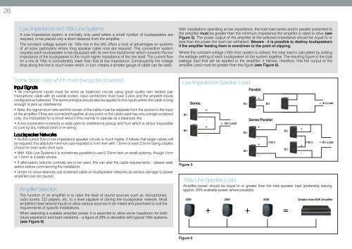
With installations operating at low impedance, the total load series and/or parallel presented to<br />
the amplifier must be greater than the minimum impedance the amplifier is rated to drive (see<br />
Figure 5). The power output of the amplifier at the selected impedance should be equal to or<br />
less than the power the load can withstand. Beware - it is possible to destroy loudspeakers<br />
if the amplifier feeding them is overdriven to the point of clipping.<br />
Where the constant voltage (<strong>100v</strong> line) system is utilised, the total load is calculated by adding<br />
the wattage setting of each loudspeaker on the system together. The resulting figure is the total<br />
wattage load that will be applied to the amplifier; it follows, therefore, that the output of the<br />
amplifier used must be greater than this figure (see Figure 6).<br />
Some basic rules which must always be observed:<br />
Input Signals<br />
• All microphone inputs must be wired as balanced circuits using good quality twin twisted pair<br />
microphone cable with an overall screen; input connectors must have 3 pins and the amplifier inputs<br />
configured as balanced. The same principal should also be applied to line inputs where the cable is long<br />
enough to pick up interference.<br />
• Note, the signal return wire and the screen of the cable must be separate from the source to the input<br />
of the amplifier. If they are connected together at any point, or the cable used has only a single screened<br />
core, it is impossible for a circuit wired in this manner to operate as a balanced line.<br />
• A line connected incorrectly is wide open to interference pickup and hum which is all but impossible<br />
to cure by any method short of re-wiring.<br />
<strong>Loudspeaker</strong> Networks<br />
• As the current flow in low impedance speaker circuits is much higher, it follows that larger cables will<br />
be required; the absolute minimum size required is 1mm twin with 1.5mm or even 2.5mm being a better<br />
choice for even quite short runs.<br />
• With <strong>100v</strong> <strong>Line</strong> Systems it is sometimes possible to use 0.75mm twin on small systems, though 1mm<br />
or 1.5mm is a better choice.<br />
• If attenuators (volume controls) are to be used, this can alter the cable requirements – please seek<br />
advice before commencing the installation.<br />
• Under no circumstances use screened cable on loudspeaker networks as serious damage to power<br />
amplifiers can be caused.<br />
Amplifier Selection<br />
The function of an amplifier is to raise the level of sound sources such as microphones,<br />
radio tuners, CD players, etc. to a level capable of driving the loudspeaker network. Most<br />
amplifiers have several inputs to allow various sources to be mixed and prioritised to suit the<br />
requirements of specific installations.<br />
When selecting a suitable amplifier power, it is essential to allow some headroom for both<br />
future expansion and load variations – a figure of 20% is desirable with typical <strong>100v</strong> systems<br />
(see Figure 6).<br />
Low Impedance Speaker Load<br />
8W<br />
8W<br />
Figure 5<br />
Series<br />
+<br />
-<br />
+<br />
-<br />
<strong>100v</strong> <strong>Line</strong> Speaker Load<br />
Amplifier power should be equal to or greater than the total speaker load (preferably leaving<br />
approx. 20% available power, where possible).<br />
20W 20W 20W<br />
+<br />
= 16W Load<br />
8W<br />
8W<br />
8W<br />
Parallel<br />
+<br />
-<br />
8W<br />
Series/Parallel<br />
+<br />
-<br />
+<br />
-<br />
(16W)<br />
8W<br />
8W<br />
+ =<br />
+<br />
-<br />
+<br />
-<br />
(16W)<br />
= 4W Load<br />
= 8W Load<br />
Greater than 60W Amplifier<br />
Figure 6