Elma 155 - Elma Instruments
Elma 155 - Elma Instruments
Elma 155 - Elma Instruments

Create successful ePaper yourself
Turn your PDF publications into a flip-book with our unique Google optimized e-Paper software.
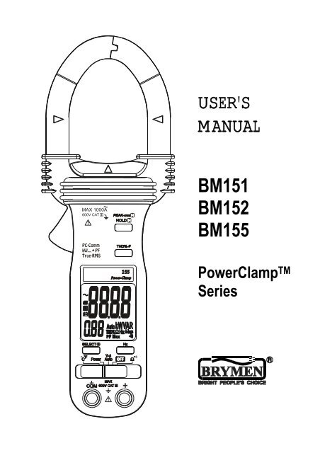
USER'S<br />
MANUAL<br />
BM151<br />
BM152<br />
BM<strong>155</strong><br />
PowerClamp TM<br />
Series
1<br />
1) SAFETY<br />
This manual contains information and warnings that must be followed for operating the<br />
instrument safely and maintaining the instrument in a safe operating condition. If the<br />
instrument is used in a manner not specified by the manufacturer, the protection<br />
provided by the instrument may be impaired.<br />
The meter meets the requirements for double insulation to IEC61010-2-032(1994),<br />
EN61010-2-032(1995), UL3111-2-032(1999):<br />
Category III 600 Volts ac and dc.<br />
PER IEC61010 OVERVOLTAGE INSTALLATION CATEGORY<br />
OVERVOLTAGE CATEGORY II<br />
Equipment of OVERVOLTAGE CATEGORY II is energy-consuming equipment to be<br />
supplied from the fixed installation.<br />
Note – Examples include household, office, and laboratory appliances.<br />
OVERVOLTAGE CATEGORY III<br />
Equipment of OVERVOLTAGE CATEGORY III is equipment in fixed installations.<br />
Note – Examples include switches in the fixed installation and some equipment for<br />
industrial use with permanent connection to the fixed installation.<br />
OVERVOLTAGE CATEGORY IV<br />
Equipment of OVERVOLTAGE CATEGORY IV is for use at the origin of the installation.<br />
Note – Examples include electricity meters and primary over-current protection<br />
equipment.<br />
TERMS IN THIS MANUAL<br />
WARNING identifies conditions and actions that could result in serious injury or even<br />
death to the user.<br />
CAUTION identifies conditions and actions that could cause damage or malfunction in<br />
the instrument.
2<br />
WARNING<br />
To reduce the risk of fire or electric shock, do not expose this product to rain or moisture.<br />
The meter is intended only for indoor use.<br />
To avoid electrical shock hazard, observe the proper safety precautions when working<br />
with voltages above 60 VDC or 30 VAC rms. These voltage levels pose a potential shock<br />
hazard to the user.<br />
Inspect test leads, connectors, and probes for damaged insulation or exposed metal<br />
before using the instrument. If any defects are found, replace them immediately.<br />
Do not touch test lead tips or the circuit being tested while power is applied to the circuit<br />
being measured. To avoid accidentally short circuit of bare (uninsulated) hazardous live<br />
conductors or busbars, switch them off before insertion and removal of the current clamp<br />
jaws. Contact with the conductor could result in electric shock. Keep your hands/fingers<br />
behind the hand/finger barriers that indicate the limits of safe access of the meter and the<br />
test leads during measurement.<br />
CAUTION<br />
Disconnect the test leads from the test points before changing meter functions.<br />
INTERNATIONAL ELECTRICAL SYMBOLS<br />
! Caution ! Refer to the explanation in this Manual<br />
Caution ! Risk of electric shock<br />
Earth (Ground)<br />
Double Insulation or Reinforced insulation<br />
Fuse<br />
AC--Alternating Current<br />
DC--Direct Current<br />
2) CENELEC Directives<br />
The instruments conform to CENELEC Low-voltage directive 73/23/EEC and<br />
Electromagnetic compatibility directive 89/336/EEC
3<br />
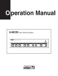
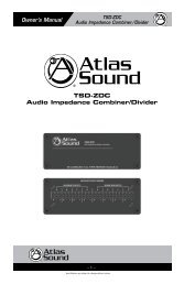
3) PRODUCT DESCRIPTION<br />
This user's manual uses only representative model(s) for illustrations. Please refer<br />
specification details for function availability to each model.<br />
1) Transformer Clamp Jaws for AC<br />
current magnetic field pick up<br />
2) Jaw marking lines for ACA (& thus<br />
Power) position error indication<br />
3) Hand/Finger Barrier to indicate the<br />
limits of safe access to the jaws<br />
during current measurements<br />
4) Push-buttons for special functions<br />
& features<br />
5) Input Jack for all functions<br />
EXCEPT non-invasive ACA current<br />
(& thus Power) function<br />
6) Common (Ground reference) Input<br />
Jack for all functions EXCEPT<br />
non-invasive ACA current (& thus<br />
Power) function<br />
7) Slide-switch Selector to turn the<br />
power ON/OFF and Select a function<br />
8) LCD display<br />
9) Jaw trigger for opening the<br />
transformer clamp jaws<br />
10) Jaw center Indicators, at where<br />
best ACA (& thus Power) accuracy is<br />
specified
4) OPERATION<br />
4<br />
AutoVA TM function<br />
Set the slide-switch function-selector to the position.<br />
●With no input, the meter displays “Auto” when it is ready.<br />
●With no ACA current input via the jaws but a voltage signal above the nominal<br />
threshold of DC 2.4V or AC 30V (40Hz ~ 500Hz) up to the rated 600V is present on<br />
V-COM terminals, the meter displays the voltage value in appropriate DC or AC,<br />
whichever larger in peak magnitude. LCD annunciator “dc” or “ ” turns on respectively.<br />
●On the contrary, with no voltage signal present on V-COM terminals but a ACA current<br />
signal above the nominal threshold of AC 1A (40Hz ~ 500Hz) up to the rated 1000A is<br />
input via the jaws, the meter displays the ACA current value. LCD annunciator “ ” turns<br />
on accordingly.<br />
●The Auto-VA feature stays at the auto-selected function as long as its signal remains<br />
above the specified threshold. Press SELECT button momentarily to manually select<br />
thru the functions ACA, ACV, DCV and then goes back to Auto-VA.<br />
CAUTION<br />
●For non-invasive ACA current measurements, press the jaw trigger and clamp the jaws
5<br />
around only one single conductor of a circuit for load current measurement. Make sure<br />
the jaws are completely closed, or else it will introduce measurement errors. Enclosing<br />
more than one conductor of a circuit will result in differential current (like identifying<br />
leakage current) measurement.<br />
●Adjacent current-carrying devices such as transformers, motors and conductor wires<br />
will affect measurement accuracy. Keep the jaws away from them as much as possible<br />
to minimize influence.<br />
THD%-F Total Harmonic Distortion - Fundamental function (model <strong>155</strong> only)<br />
THD%-F = (Total Harmonics RMS / Fundamental RMS) x 100%<br />
Total Harmonic Distortion - Fundamental (THD%-F) is the percentage ratio of the Total<br />
Harmonics RMS value to the Fundamental RMS value of a voltage or current signal, and<br />
is given by the above expression. An ideal sinusoidal waveform has a value of 0 THD%.<br />
A badly distorted sinusoidal waveform may have a much higher THD% value of up to<br />
several hundreds.<br />
When the meter is in ACV or ACA function, THD%-F values up to 99 THD% will be<br />
displayed in the secondary mini display automatically. Press THD%-F button<br />
momentarily toggles THD% readings to main display to get full readings up to 999.9<br />
THD%.
6<br />
Line-level Frequency function<br />
When ACV or ACA function is auto-selected or manual-selected, press Hz button<br />
momentarily toggles to Line-level Frequency function. Frequency trigger levels vary<br />
automatically with function ranges.<br />
Peak-rms mode<br />
Peak-rms compares and displays the maximum RMS value of surge voltage or<br />
current with durations as short as 65ms. When ACV or ACA function is auto-selected or<br />
manual-selected, press and hold Peak-rms button for one second or more toggles to<br />
this mode. The LCD annunciators “P-” & “Max” turn on.<br />
Note:<br />
Manually disable the APO feature (press & hold the HOLD button while setting the<br />
slide-switch function-selector from any position to the position.) before using<br />
Peak-rms mode for long-term measurements.<br />
HOLD mode<br />
Hold mode freezes the display for later viewing. When any function is auto-selected or<br />
manual-selected, press HOLD button momentarily toggles to this mode. The<br />
annunciator “ ” turns on.
7<br />
Notes on Displacement Power Factor & Total Power Factor<br />
●Introduction: Power is the rate of change of energy with respect to time (in terms of<br />
voltage V and current A). Instantaneous (real) power w = vi where v is the instantaneous<br />
voltage and i the instantaneous current. The average (real) power is the mean of vi and<br />
is given by:<br />
W = ω/2π∫vi dt , over the interval from 0 to 2π/ω<br />
●Displacement Power Factor (more traditional): Assuming V and A are pure<br />
sinusoidal waveforms without harmonics (as in most traditional cases), that is, v = V sin<br />
ωt and i = I sin (ωt -θ), the expression can be simplified to:<br />
W = 1/2 x V x I x Cosθ where V and I are the peak values, θ is the displacement<br />
power factor angle, and Cosθ is the displacement power factor. Using RMS values, it is<br />
written as:<br />
W = Vrms x Arms x Cosθ<br />
Practically, in such cases without harmonics, θ is also called the phase-shift angle of<br />
the current A to the voltage V. An inductive circuit is said to have a lagging power factor<br />
since current A lags voltage V (phase-shift angle θ and thus Sinθ are both “+”), and a<br />
capacitive circuit is said to have a leading power factor since current A leads voltage V<br />
(phase-shift angle θ and thus Sinθ are both “-”).<br />
●Total Power Factor (encountering harmonics): When encountering distorted<br />
waveforms with the presence of harmonics, however, the simplified power expression<br />
should not be used since substituting the above mentioned pure sinusoidal V and A<br />
functions cannot fulfill the actual conditions. Cosine of phase-shift angle (Cosθ), or the<br />
displacement power factor, is no longer the only component constituting the overall<br />
power factor. Harmonics do increase apparent power and thus decrease the overall<br />
power factor. That is, the Total Power Factor is actually affected by both phase-shift<br />
angle and harmonics, and is given by the expression:<br />
Total Power Factor (PF) = Real Power (W) / Apparent Power (VA)<br />
In order to improve overall system power factor, nowadays power-system engineer<br />
needs to address both phase-shift and harmonics problems. Practically, harmonics<br />
should be dealt with (e.g. filtering out) before phase-shift to be corrected (e.g. installing<br />
capacitors in parallel with inductive loads).<br />
Power function<br />
Set the slide-switch function-selector to the Power position.<br />
●Default at last selected function. Press SELECT button momentarily selects between<br />
W (real power), VAR (reactive power) & VA (apparent power) measurement functions.
8<br />
●PF (Total Power Factor) displays simultaneously in the secondary mini display.<br />
Denoting efficiency, absolute PF value is adopted.<br />
●“A-lags” LCD annunciator turns on to indicate an inductive circuit, or Current A lags<br />
Voltage V (i.e., phase-shift angle θ is “+”).<br />
On the contrary, together with significant PF values, WITHOUT turning on “A-lags”<br />
indicates a capacitive circuit, or Current A leads Voltage V (i.e., phase-shift angle θ is<br />
“-”).<br />
Note:<br />
1. When measuring load circuits with power absorptions as in most applications, positive<br />
W (Real Power) readings indicate correct measurement setups. Negative readings (LCD<br />
annunciator “-“ turns on) indicate either the clamp-on jaws direction or the test leads<br />
polarity is reversed in such cases. Correct the setups to get proper “A-lags” indications.<br />
2. When encountering largely distorted waveforms, “A-lags” detection might be affected<br />
due to the influence of harmonics. As mentioned, it is recommended to deal with (e.g.<br />
filter out) harmonics before correcting phase-shift problems.<br />
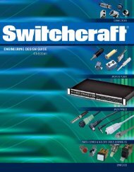
●Measuring One or Single Phase Power Parameters:
9<br />
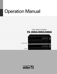
●Measuring 3-Phase 4-Wire (3<br />
4W) Power Parameters:<br />
In both un-balanced and balanced load cases, 3-Phase 4-Wire (3 4W) systems,<br />
measure the phase-to-neutral powers kW1, kW2 and kW3 of each phase separately as<br />
illustrated. System (total) power kWTotal is the summation of all three phase-to-neutral<br />
powers. That is:<br />
kWTotal = kW1 + kW2 + kW3 (for both un-balanced and balanced load cases)<br />
In balanced load cases, 3-Phase 4-Wire (3 4W) systems, the system (total) power<br />
parameters can be simplified to three times of any of the phase-to-neutral powers. That<br />
is:<br />
kWTotal = 3 x kW1<br />
(for balanced load cases only)<br />
kVATotal = 3 x kVA1<br />
(for balanced load cases only)<br />
kVARTotal = 3 x kVAR1 (for balanced load cases only)
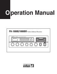
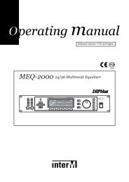
●Measuring 3-Phase 3-Wire (3<br />
3W) Power Parameters:<br />
10<br />
In both un-balanced and balanced load cases, 3-Phase 3-Wire (3 3W) systems,<br />
measure the power components kW1 and kW2 separately as illustrated. System (total)<br />
power kWTotal is the summation of the two measured power components. That is:<br />
kWTotal = kW1 + kW2 (for both un-balanced and balanced load cases)<br />
In balanced load cases, 3-Phase 3-Wire (3 3W) systems, the system (total) power<br />
parameters can be achieved by the following expressions:<br />
kWTotal = kW1 + kW2<br />
(same as above)<br />
kVATotal = √3 x kVA1<br />
(for balanced load cases only)<br />
kVARTotal = √(kVATotal 2 - kWTotal 2 ) (for balanced load cases only)
11<br />
Temperature function (model 152 & <strong>155</strong> only)<br />
Set the slide-switch function-selector to the o C/ o F position. Default at last selected<br />
function. Press SELECT button to toggle between o C and o F measurement functions. Be<br />
sure to insert the banana-plug type-K temperature bead probe Bkp60 at correct<br />
polarities. You can also use a plug adapter Bkb32 (Optional purchase) with banana pins<br />
to type-K socket to adapt other type-K standard mini plug temperature probes.<br />
Ω/ functions<br />
Set the slide-switch function-selector to the Ω/ function position. Default at last<br />
selected function. Press SELECT button to toggle between Ω and measurement<br />
functions.<br />
Backlighted display (models 152 & <strong>155</strong> only)<br />
Press the SELECT button for 1 second or more to toggle the display backlight on or off.<br />
Auto Power Off (APO)<br />
The meter turns off after approximately 17 minutes of neither switch nor button activity.<br />
To wake up the meter from APO, slide the function-selector to other positions and back<br />
on again. Always turn the function-selector to OFF when the meter is not in use.
12<br />
Disabling Auto-Power-Off (APO)<br />
Press-and-hold the HOLD button while sliding the function-selector to a (designated)<br />
function-selector position. This disables the Auto-Power-Off feature of the functions on<br />
that particular function-selector position. The LCD displays “ ” & “ ” to confirm<br />
activation right after the HOLD button is released. Slide the function-selector to any other<br />
positions then resumes Auto-Power-Off feature.<br />
RS232C PC computer interface capabilities<br />
The instrument equips with an optical isolated data output port at the bottom case near<br />
the battery compartment. Optional purchase PC interface kit BR15X (including BA-1XX<br />
Optical Adapter Back, BC-100R Cable & Bs15x Software CD) is required to connect the<br />
meter to PC computer thru RS232C protocol. The RS232C Data Recording System<br />
software Bs15x equips with a digital meter, an analog meter, a comparator meter, and a<br />
Data Graphical recorder. Refer to the README file comes with the interface kit for<br />
further details.<br />
Press-and-hold the Hz button while sliding the function-selector to a (designated)<br />
function-selector position. This enables data output of the functions on that particular<br />
function-selector position. The LCD displays “ ” to confirm activation right after the Hz<br />
button is released. Slide the function-selector to any other positions then disables data<br />
output.<br />
5) MAINTENANCE<br />
WARNING<br />
To avoid electrical shock, disconnect the meter from any circuit, remove the test leads<br />
from the input jacks and turn OFF the meter before opening the case. Do not operate<br />
with open case.<br />
Trouble Shooting<br />
If the instrument fails to operate, check batteries and test leads etc., and replace as<br />
necessary. Double check operating procedure as described in this user’s manual<br />
If the instrument voltage-resistance input terminal has subjected to high voltage transient<br />
(caused by lightning or switching surge to the system) by accident or abnormal<br />
conditions of operation, the series fusible resistors will be blown off (become high<br />
impedance) like fuses to protect the user and the instrument. Most measuring functions<br />
through this terminal will then be open circuit. The series fusible resistors and the spark<br />
gaps should then be replaced by qualified technician. Refer to the LIMITED WARRANTY<br />
section for obtaining warranty or repairing service.
13<br />
Cleaning and Storage<br />
Periodically wipe the case with a damp cloth and mild detergent; do not use abrasives or<br />
solvents. If the meter is not to be used for periods of longer than 60 days, remove the<br />
batteries and store them separately<br />
Battery replacement<br />
The meter uses standard 1.5V AAA Size (NEDA 24A or IEC LR03) battery X 2<br />
Loosen the 2 captive screws from the battery cover case. Lift the battery cover case.<br />
Replace the batteries. Replace battery cover case. Re-fasten the screws.<br />
6) Specifications<br />
General Specifications<br />
Display :<br />
Voltage functions: 6000 counts LCD display(s)<br />
Power, Ohm & Hz functions: 9999 counts LCD display(s)<br />
ACA clamp-on function: 4000 counts LCD display(s)
14<br />
Update Rate :<br />
Power function: 1 per second nominal<br />
Voltage, ACA clamp-on, Ohm, Hz & Temperature functions: 4 per second nominal<br />
Polarity : Automatic<br />
Low Battery : Below approx. 2.4V<br />
Operating Temperature : 0 o C to 40 o C<br />
Relative Humidity : Maximum relative humidity 80% for temperature up to 31 o C<br />
decreasing linearly to 50% relative humidity at 40 o C<br />
Altitude : Operating below 2000m<br />
Storage Temperature : -20 o C to 60 o C, < 80% R.H. (with battery removed)<br />
Temperature Coefficient : nominal 0.15 x (specified accuracy)/ o C @(0 o C -18 o C or<br />
28 o C -40 o C), or otherwise specified<br />
Sensing : True RMS sensing for all models<br />
Safety : Meets IEC61010-2-032 (1994), EN61010-2-032(1995), UL3111-2-032(1999).<br />
Measurement Category : III 600 Volts ac & dc<br />
Transient protection : 6.5kV (1.2/50μs surge) for all models<br />
Pollution degree : 2<br />
E.M.C. : Meets EN61326(1997, 1998/A1), EN61000-4-2(1995), and EN61000-4-3(1996)<br />
In an RF field of 3V/m:<br />
Total Accuracy = Specified Accuracy + 45 digits<br />
Performance above 3V/m is not specified<br />
Overload Protections :<br />
ACA Clamp-on jaws : AC 1000A rms continuous<br />
+ & COM terminals (all functions) : 600VDC/VAC rms<br />
Power Supply : standard 1.5V AAA Size (NEDA 24A or IEC LR03) battery X 2<br />
Power Consumption :<br />
Voltage, ACA, Hz & Power functions: 10mA typical<br />
Ohm & Temperature functions: 4mA typical<br />
APO Timing : Idle for 17 minutes<br />
APO Consumption : 10μA typical<br />
Dimension : L224mm X W78mm X H40mm<br />
Weight : 224 gm approx<br />
Jaw opening & Conductor diameter : 45mm max<br />
Special features : Backlight display (model 152 & <strong>155</strong> only); AutoVA TM (Auto Selection<br />
on ACV, DCV or ACA functions); Power measurement of selectable W, VAR & VA with<br />
dual-display Total Power Factor features; Total harmonic distortion THD%-F (model <strong>155</strong><br />
only); PEAK-rms HOLD
15<br />
Accessories : Test leads (pair), batteries installed, user's manual, soft carrying pouch,<br />
& BKP60 banana plug type-K thermocouple (model 152 & <strong>155</strong> only)<br />
Optional accessories : BR15X PC interface kit (including BA-1XX optical adapter back,<br />
BC-100R cable & Bs15x software CD), BKB32 banana plug to type-K socket plug<br />
adaptor (model 152 & <strong>155</strong> only)<br />
Electrical Specifications<br />
Accuracy is ±(% reading digits + number of digits) or otherwise specified, at 23 o C ±5 o C<br />
& less than 75% R.H.<br />
True RMS (all models) ACV & ACA clamp-on accuracies are specified from 0% to 100%<br />
of range or otherwise specified. Maximum Crest Factor are as specified below, and with<br />
frequency spectrums, besides fundamentals, fall within the meter specified AC<br />
bandwidth for non-sinusoidal waveforms. Fundamentals are specified at 50Hz and<br />
60Hz.<br />
AC Voltage<br />
RANGE<br />
Accuracy<br />
50Hz / 60Hz<br />
600.0V 0.5% + 5d<br />
45Hz ~ 500Hz<br />
600.0V 1.5% + 5d<br />
500Hz ~ 3.1kHz<br />
600.0V 2.5% + 5d<br />
CMRR : >60dB @ DC to 60Hz, Rs=1kΩ<br />
Input Impedance: 2MΩ, 30pF nominal<br />
Crest Factor:<br />
< 2.3 : 1 at full scale & < 4.6 : 1 at half scale<br />
ACV AutoVA TM Threshold: 30VAC (40Hz ~ 500Hz only) nominal<br />
DC Voltage<br />
RANGE<br />
Accuracy<br />
600.0V 0.5% + 5d<br />
NMRR : >50dB @ 50/60Hz<br />
CMRR : >120dB @ DC, 50/60Hz, Rs=1kΩ<br />
Input Impedance: 2MΩ, 30pF nominal<br />
DCV AutoVA TM Threshold: 2.4VDC nominal
PEAK-rms HOLD (ACA & ACV only)<br />
Response: 65ms to 90%<br />
16<br />
Ohms<br />
RANGE<br />
Accuracy<br />
999.9Ω 1.0% + 6d<br />
Open Circuit Voltage : 0.4VDC typical<br />
Audible Continuity Tester<br />
Audible threshold: between 10Ω and 300Ω.<br />
Response time: 250μs<br />
ACA Current (Clamp-on)<br />
RANGE Accuracy<br />
1) 2)<br />
50Hz / 60Hz<br />
40.00A, 400.0A, 1000A<br />
1.0% + 5d<br />
45Hz ~500Hz<br />
40.00A, 400.0A<br />
2.0% + 5d<br />
1000A<br />
2.5% + 5d<br />
500Hz ~ 3.1kHz<br />
40.00A, 400.0A<br />
2.5% + 5d<br />
1000A<br />
3.0% + 5d<br />
ACA AutoVA TM Threshold: 1A AC (40Hz ~ 500Hz only) nominal<br />
Crest Factor:<br />
< 2.5 : 1 at full scale & < 5.0 : 1 at half scale for 40.00A & 400.0A ranges<br />
< 1.4 : 1 at full scale & < 2.8 : 1 at half scale for 1000A range<br />
1)<br />
Induced error from adjacent current-carrying conductor: < 0.06A/A<br />
2)<br />
Specified accuracy is from 1% to 100% of range and for measurements made at the jaw<br />
center. When the conductor is not positioned at the jaw center, position errors introduced<br />
are:<br />
Add 1% to specified accuracy for measurements made WITHIN jaw marking lines<br />
(away from jaw opening)<br />
Add 4% to specified accuracy for measurements made BEYOND jaw marking lines<br />
(toward jaws opening)
Temperature (model 152 & <strong>155</strong> only)<br />
RANGE<br />
Accuracy<br />
-50 o C ~ 300 o C 2.0% + 3 o C<br />
-58 o F ~ 572 o F 2.0% + 6 o F<br />
Type-K thermocouple range & accuracy not included<br />
Add 3 o C (or 6 o F) to specified accuracy @ -20 o C ~ -50 o C (or @ -4 o F ~ -58 o F)<br />
17<br />
Frequency<br />
RANGE<br />
5.00Hz ~ 500.0Hz<br />
Sensitivity (Sine RMS)<br />
40A range: > 4A<br />
400A range: > 40A<br />
1000A range: > 400A<br />
600V range: > 30V<br />
Accuracy<br />
0.5%+4d<br />
THD%-F 1) (model <strong>155</strong> only)<br />
RANGE Harmonic order Accuracy 3)<br />
Fundamental<br />
1.5% of Reading + 6d<br />
2nd ~ 3rd<br />
5.0% of Reading + 6d<br />
0.0% ~999.9% 2) 4th ~ 16th<br />
2.5% of Reading + 6d<br />
17th ~ 46th<br />
3.0% of Reading + 6d<br />
47th ~ 51st 4.5% of Reading + 6d<br />
1)<br />
THD-F is defined as:<br />
(Total Harmonic RMS / Fundamental RMS) x 100%<br />
2)<br />
Range for Dual Display mode: 0% ~ 99%<br />
3)<br />
Specified accuracy @ ACA fundamental > 5A ; ACV fundamental > 50V<br />
Total Power Factor (PF)<br />
RANGE Accuracy 1)<br />
0.10 ~ 0.99<br />
F ~ 21st<br />
22nd ~ 51st<br />
3d<br />
5d<br />
1)<br />
Specified accuracy @ ACA fundamental > 2A ; ACV fundamental > 50V
Power<br />
RANGE<br />
Accuracy<br />
1) 2)<br />
0 ~ 600.0kVA F ~ 10th 11th ~ 46th 47th ~ 51st<br />
@ PF = 0.99 ~ 0.1 2.0%+6d 3.5%+6d 5.5%+6d<br />
18<br />
RANGE<br />
Accuracy<br />
1) 3)<br />
0 ~ 600.0kW / kVAR F ~ 10th 11th ~ 25th 26th ~ 46th 47th ~ 51st<br />
@ PF = 0.99 ~ 0.70 2.0%+6d 3.5%+6d 4.5%+6d<br />
@ PF = 0.70 ~ 0.50 3.0%+6d<br />
10%+6d<br />
@ PF = 0.50 ~ 0.30<br />
4.5%+6d<br />
@ PF = 0.30 ~ 0.20 10%+6d 15%+6d<br />
1)<br />
Specified accuracy is for ACA clamp measurement at the center of jaws. When the<br />
conductor is not positioned at the jaw center, position errors introduced are:<br />
Add 1% to specified accuracy for ACA measurements made WITHIN jaw marking<br />
lines (away from jaw opening)<br />
Accuracy is not specified for ACA measurement made BEYOND jaw marking lines<br />
(toward jaws opening)<br />
2)<br />
Add 1% to specified accuracy @ ACA fundamental < 5A or ACV fundamental < 90V.<br />
Accuracy is not specified @ ACA fundamental < 1A or ACV fundamental < 30V<br />
3)<br />
Add 1% to specified accuracy @ ACA fundamental < 5A or ACV fundamental < 90V.<br />
Accuracy is not specified @ ACA fundamental < 2A or ACV fundamental < 50V<br />
A-lags 1) Indication:<br />
“A-lags” LCD annunciator turns on to indicate an inductive circuit, or Current A lags<br />
Voltage V (i.e., phase-shift angleθ is “+”).<br />
1)<br />
A-lags Indication is specified at 50/60Hz fundamental without harmonics, and at ACV ><br />
90V, ACA > 9A, & PF < 0.95
LIMITED WARRANTY<br />
BRYMEN warrants to the original product purchaser that each product it manufactures<br />
will be free from defects in material and workmanship under normal use and service<br />
within a period of one year from the date of purchase. BRYMEN's warranty does not<br />
apply to accessories, fuses, fusible resistors, spark gaps, batteries or any product which,<br />
in BRYMEN's opinion, has been misused, altered, neglected, or damaged by accident or<br />
abnormal conditions of operation or handling.<br />
To obtain warranty service, contact your nearest BRYMEN authorized agent or send the<br />
product, with proof of purchase and description of the difficulty, postage and insurance<br />
prepaid, to BRYMEN TECHNOLOGY CORPORATION. BRYMEN assumes no risk for<br />
damage in transit. BRYMEN will, at its option, repair or replace the defective product free<br />
of charge. However, if BRYMEN determines that the failure was caused by misused,<br />
altered, neglected, or damaged by accident or abnormal conditions of operation or<br />
handling, you will be billed for the repair.<br />
THIS WARRANTY IS EXCLUSIVE AND IS IN LIEU OF ALL OTHER WARRANTIES,<br />
EXPRESSED OR IMPLIED, INCLUDING BUT NOT LIMITED TO ANY IMPLIED<br />
WARRANTY OR MERCHANTABILITY OR FITNESS FOR A PARTICULAR PURPOSE<br />
OR USE. BRYMEN WILL NOT BE LIABLE FOR ANY SPECIAL, INDIRECT,<br />
INCIDENTAL OR CONSEQUENTIAL DAMAGES.<br />
BRYMEN TECHNOLOGY CORPORATION<br />
TEL:+886 2 2226 3396<br />
FAX:+886 2 2225 0025<br />
http://www.brymen.com<br />
PRINTED ON RECYCLABLE PAPER, PLEASE RECYCLE<br />
COPYRIGHT © MMV Btc, ALL RIGHTS RESERVED<br />
P/N:7M1C-0591-0000<br />
PRINTED IN TAIWAN