3.0 Electrical installation - UNITEK Industrie Elektronik GmbH
3.0 Electrical installation - UNITEK Industrie Elektronik GmbH
3.0 Electrical installation - UNITEK Industrie Elektronik GmbH

You also want an ePaper? Increase the reach of your titles
YUMPU automatically turns print PDFs into web optimized ePapers that Google loves.
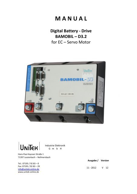
M A N U A L<br />
Digital Battery - Drive<br />
BAMOBIL – D3.2<br />
for EC – Servo Motor<br />
<strong>Industrie</strong> <strong>Elektronik</strong><br />
G m b H<br />
Hans-Paul-Kaysser-Straße 1<br />
71397 Leutenbach – Nellmersbach<br />
Tel.: 07195 / 92 83 – 0<br />
Fax: 07195 / 92 83 – 29<br />
info@unitek-online.de<br />
www.unitek-online.de<br />
Ausgabe /<br />
Version<br />
11 - 2012 V 12
1.0 Basic information<br />
C O N T E N T S<br />
C O N T E N T S<br />
C O N T E N T S ................................................................................................................................ 1<br />
1.0 Basic information ......................................................................................................................... 3<br />
1.1 History ...................................................................................................................................... 3<br />
1.2 Further <strong>UNITEK</strong> products ......................................................................................................... 3<br />
1.3 Engineering instructions (MANUAL)........................................................................................ 3<br />
1.4 Validity ...................................................................................................................................... 4<br />
1.5 Designations and symbols ........................................................................................................ 4<br />
1.6 General product information .................................................................................................. 5<br />
1.7 Application/build/features ....................................................................................................... 6<br />
1.8 Safety regulations .................................................................................................................... 8<br />
1.9 Commissioning ...................................................................................................................... 10<br />
1.10 Safety advices ...................................................................................................................... 11<br />
1.11 Intended applications ........................................................................................................... 12<br />
1.12 Regulations and guidelines .................................................................................................. 13<br />
1.13 Risks ...................................................................................................................................... 14<br />
1.14 Technical data ...................................................................................................................... 15<br />
2.0 Mechanical <strong>installation</strong> .............................................................................................................. 17<br />
2.1 Important instruction ............................................................................................................. 17<br />
2.2 Dimensions BAMOBIL D3 ....................................................................................................... 18<br />
2.3 Dimensions - with an additional cooling unit ......................................................................... 19<br />
2.4 Mounting ................................................................................................................................ 20<br />
<strong>3.0</strong> <strong>Electrical</strong> <strong>installation</strong> .................................................................................................................. 22<br />
3.1 Important advice ................................................................................................................... 22<br />
3.2 Circuit diagram ....................................................................................................................... 23<br />
3.3 Connection diagram ............................................................................................................... 25<br />
3.4 EMC advice ............................................................................................................................. 26<br />
3.5 Connectors ............................................................................................................................. 27<br />
3.6 Battery connection ................................................................................................................. 28<br />
3.7 Motor connection .................................................................................................................. 31<br />
3.8 Control signals ........................................................................................................................ 32<br />
3.9 Safety input RFE (Rotating field enable) ................................................................................ 33<br />
3.10 Digital logic outputs (open emitter) ..................................................................................... 34<br />
3.11 Serial interface RS 232.......................................................................................................... 36<br />
3.12 CAN bus ................................................................................................................................ 37<br />
3.13 Resolver connection ............................................................................................................. 38<br />
1 BAMOBIL – D3.2
1.0 Basic information<br />
3.14 Encoder TTL connection ....................................................................................................... 39<br />
3.15 SIN COS 1Vss connection ...................................................................................................... 41<br />
3.16 Rotor position encoder - connection via a bl-tacho ............................................................. 42<br />
3.17 X8 TTL encoder output or input (2)...................................................................................... 43<br />
3.18 Displays - BAMOBIL D3 ......................................................................................................... 45<br />
3.19 Error displays - BAMOBIL D3 ................................................................................................ 46<br />
3.20 Warning signals - BAMOBIL D3............................................................................................. 47<br />
3.21 Measured data ..................................................................................................................... 48<br />
3.22 Output stage temperature ................................................................................................... 49<br />
4.0 Warranty..................................................................................................................................... 50<br />
C O N T E N T S<br />
BAMOBIL – D3.2 2
1.0 Basic information<br />
1.1 History<br />
1.0 Basic information<br />
1.1 History<br />
Version Modification Date<br />
04/2012 – V9 Text and drawing adjustments<br />
11-2012 V11 Basic information / graphics - drawings<br />
11-2012 V12 Bamobil D3.2-160 deleted / Firmware state deleted 16.10.2013<br />
1.2 Further <strong>UNITEK</strong> products<br />
Digital servo-amplifiers for small power values >>> <strong>UNITEK</strong> DS205, DS403<br />
Analog three-phase servo-amplifiers<br />
>>> <strong>UNITEK</strong> Series<br />
TVD3, TVD6, AS<br />
Analog dc servo-amplifiers<br />
>>> <strong>UNITEK</strong> Series<br />
TV3, TV6, TVQ6<br />
Thyristor current converters<br />
1Q, 4Q, Servo<br />
>>> <strong>UNITEK</strong> Series Classic<br />
200W to 800kW<br />
DC and ac servo-amplifiers for battery operation<br />
Series BAMO<br />
A2, A3, D3<br />
Analog and digital<br />
Series BAMOBIL<br />
Series BAMOCAR<br />
1.3 Engineering instructions (MANUAL)<br />
1. MANUAL BAMOBIL-D3 Hardware<br />
2. MANUAL NDrive2 Software<br />
3. MANUAL DS, DPC Commissioning -<br />
Troubleshooting<br />
Use all three MANUALs for the engineering, the <strong>installation</strong>, and the commissioning!<br />
CD (<strong>UNITEK</strong>-DOKU-SOFT) supplied with the delivery of the units.<br />
Online available as download version on the <strong>UNITEK</strong> website (www.unitek-online.de or<br />
www.unitek-online.eu).<br />
The hardware MANUAL comprises warning and safety advices, explanations of standards,<br />
mechanical and electrical <strong>installation</strong> advices.<br />
The MANUAL must be available for all persons who are concerned with the unit.<br />
3 BAMOBIL – D3.2
1.0 Basic information<br />
1.4 Validity<br />
Hardware state:<br />
Firmware state:<br />
1.4 Validity<br />
1.5 Designations and symbols<br />
Unit<br />
User:<br />
Manufacturer:<br />
BAMOBIL<br />
Manufacturers or operators of machines or <strong>installation</strong>s in the industrial<br />
sector (B2B, secondary environment)<br />
<strong>UNITEK</strong> <strong>Industrie</strong> <strong>Elektronik</strong> <strong>GmbH</strong><br />
Dealer:<br />
Caution - Danger to life!<br />
High voltage<br />
Warning!<br />
Important<br />
BAMOBIL – D3.2 4
1.0 Basic information<br />
1.6 General product information<br />
1.6 General product information<br />
The digital current servo amplifiers BAMOxxx in combination with the motor provide a 4-<br />
quadrant drive which can be used in both rotation directions for drive operations and brake<br />
operations with energy feed-back.<br />
According to the installed parameter components the amplifiers are suitable for EC synchronous<br />
motors, ac asynchronous motors, or dc motors.<br />
The individual drive versions have different advantages and disadvantages:<br />
The EC drive (synchronous motors) has the highest efficiency and performance per weight and<br />
volume and provide a drive solution free of maintenance and with a wide dynamic control range.<br />
However, the high braking torque in case of motor short-circuits is a disadvantage and it is also<br />
difficult to control the field weakening range.<br />
From the electrical view, the EC synchronous motor (brushless dc motor) is a synchronous motor<br />
with a permanent magnet rotor and a three-phase current stator.<br />
The physical characteristics correspond to those of dc motors, i.e., the current is proportional to<br />
the torque and the voltage is proportional to the speed. The speed is steadily controlled up to the<br />
current limit (max. torque). In case of an overload the speed drops and the current remains<br />
constant.<br />
The speed/torque characteristic is rectangular.<br />
Current, speed, and position are precisely measured. The field frequency is not controllable, it is<br />
automatically adjusted.<br />
The motor voltages and the motor currents are sinusoidal.<br />
The ac drive (asynchronous motors) has the widest speed range due to the single field weakening<br />
and there is no braking torque in case of a motor circuit. The unit size and the worse efficiency.<br />
The rotating field frequency can be controlled in due consideration of the motor specific<br />
parameters (field-based control). The motor voltages and motor currents are sinusoidal.<br />
The active current and the magnetising current must be supplied by the controller.<br />
With both 3-phase current systems there will be no motor movement neither when the rotating<br />
field is switched off nor in case of an output stage damage. Most of the heat losses are generated<br />
in the motor stator.<br />
The dc drive (dc motor) has the most uniform running and a wide control range. It is possible to<br />
provide an emergency operation by directly connecting the battery voltage. The carbon brushes<br />
and the heat development in the armature are disadvantages. The drive may run at high speed in<br />
case of an output stage damage.<br />
The current is proportional to the torque and the voltage is proportional to the speed.<br />
Current, speed, and position are precisely measured. The speed is steadily controlled up to the<br />
current limit (max. torque). In case of an overload the speed drops and the current remains<br />
constant. The speed/torque characteristic is rectangular.<br />
Field weakening might occur with separately excited motors.<br />
The Bamobil D3 can be used as position amplifier or torque or speed amplifier.<br />
The speed actual value is generated in the encoder unit (resolver or others) or internally<br />
generated (without sensors). It is necessary to provide an encoder system for wide control ranges<br />
and high control dynamics.<br />
5 BAMOBIL – D3.2
1.0 Basic information<br />
1.7 Application/build/features<br />
Application in all kinds of vehicles, machines and <strong>installation</strong>s with a drive power of 7,5 kW,<br />
Especially as 4Q-servo-drive for<br />
- highly dynamic acceleration an d braking cycles<br />
- a wide control range<br />
- a high efficiency<br />
- small motor dimensions<br />
- a uniform, accurate and smooth running<br />
To be used for the speed or torque control or combined speed/torque control incorporated<br />
within or independent of position control loops.<br />
1.7 Application/build/features<br />
Particularly suitable for:<br />
Battery-driven vehicles such as electric vehicles and boats, forklifts, transportation systems as well<br />
as battery-supplied machines and <strong>installation</strong>s such as assembly machines, metal working<br />
machines, food processing machines, robots and handling systems, conveyors, stone working<br />
machines, and for many other battery-supplied applications.<br />
Build:<br />
- Compact devices according to the VDE, DIN and EU regulations, protection rating IP40<br />
- For
1.0 Basic information<br />
1.7 Application/build/features<br />
Features:<br />
Battery-powered of dc connection 24V= bis 48V (24V= to 120V=)<br />
Independent auxiliary voltage connection 24V=<br />
Digital interfaces RS232, CAN-BUS (further option)<br />
2 analogue inputs, programmable differential input<br />
4 digital inputs / outputs, programmable, optically de-coupled<br />
Linear command value ramp, non-linear (s-function)<br />
Logic for enable and the output stage switch<br />
BTB-ready for operation, solid state relay contact<br />
Position, speed and torque control<br />
Resolver or incremental encoder TTL, SINCOS 1Vss, rotor position +bl tacho<br />
Encoder output or 2 nd encoder input<br />
Static and dynamic current limiting<br />
Uniform, completely digital control unit<br />
Protective switch-off from the motor in case of over-voltage, under-voltage, or<br />
overtemperature<br />
Intrinsically safe and short-circuit proof power section<br />
Processor-independent hardware switch-off in case of short-circuits, circuits to earth,<br />
overvoltage and over-temperature of the amplifier.<br />
7 BAMOBIL – D3.2
1.0 Basic information<br />
1.8 Safety regulations<br />
Electronic equipment is not fault proof!<br />
Caution - High voltage<br />
DC 160 V=<br />
Shock hazard! / Danger to life!<br />
Discharge time of the bus circuit >4 min!<br />
1.8 Safety regulations<br />
Before <strong>installation</strong> or commissioning begins, this manual must be thoroughly read and<br />
understood by the skilled technical staff involved. It must be ensured that the documentation<br />
(manuals) and thus, the knowledge of the unit and especially the safety advices must be available<br />
for all persons who are concerned with the unit<br />
If any uncertainty arises or if any function is not or not sufficiently described in the<br />
documentation, the manufacturer or dealer should be contacted.<br />
Any incorrect <strong>installation</strong>/connection may damage the device!<br />
Any incorrect programming may cause dangerous movements!<br />
Intended applications:<br />
The devices of the BAMOBIL series are power electric parts used for regulating energy flow.<br />
They are designed to control EC synchronous motors and ac asynchronous motors in stationary<br />
machines or <strong>installation</strong>s for industrial applications.<br />
For applications in residential areas additional EMC measures are necessary.<br />
Any other type of application must be approved by the manufacturer.<br />
The user must draw up a hazard analysis for his end product.<br />
Protection rating IP20 (version BAMOBIL 65 for IP65)<br />
Connection only to batteries<br />
Operation only allowed when the switch cabinet is closed or<br />
locked!<br />
The control and power connections may be voltage-carrying<br />
without the axis operating!<br />
The discharge time of the bus circuit is superior to 4 min!<br />
Measure the voltage before any disassembly!<br />
BAMOBIL – D3.2 8
1.0 Basic information<br />
1.8 Safety regulations<br />
The user must draw up a hazard analysis for his machine, vehicle, or <strong>installation</strong>.<br />
The user must ensure that in the event of:<br />
- device failure<br />
- incorrect operation,<br />
- loss of regulation or control<br />
the axis will be safely de-activated.<br />
It must also be ensured that the machines, equipment, or<br />
vehicles are fitted with device independent monitoring and<br />
safety features.<br />
Appropriate measures must be taken so that man as well as<br />
property are not exposed to danger due to incorrect or improper<br />
movements at any time!<br />
During operation the switch cabinet must be closed and the<br />
safety systems must be enabled.<br />
When the switch cabinet is open and/or the safety systems are<br />
de-activated, it must be ensured by the operator that only skilled<br />
and suitably trained personnel has access to the units.<br />
Assembly<br />
- should only be carried out when all voltages have been removed and the units are secured<br />
- should only be carried out by suitably trained personnel<br />
Installation<br />
- should only be carried out when all voltages have been removed and the units are secured<br />
- should only be carried out by suitably trained personnel for electrics<br />
- should only be carried out in accordance with health and safety guidelines<br />
Adjustments and programming<br />
- should only be carried out by suitably trained personnel with knowledge in electronic drives and<br />
software<br />
- should only be carried out in accordance with the programming advice<br />
- should only be carried out in accordance with health and safety guidelines<br />
9 BAMOBIL – D3.2
1.0 Basic information<br />
1.9 Commissioning<br />
When mounting the units into machines and <strong>installation</strong>s the proper operation of the units may<br />
not be started until it is ensured that the machine, the <strong>installation</strong>, or the vehicle comply with the<br />
regulations of the EC machinery directive 2006/42/EG and the EMC guideline 2004/108/EG.<br />
On the <strong>installation</strong> and test conditions described in the chapter 'EMV advices' it is adhered to the<br />
EC guideline 2004/108/EG including the EMC standards EN61000-2 and EN61000-4.<br />
1.9 Commissioning<br />
For applications in residential areas additional EMC measures are necessary.<br />
A manufacturer's declaration can be requested.<br />
The manufacturer of the machine or <strong>installation</strong> is responsible for observing the threshold values<br />
demanded by the EMC laws.<br />
BAMOBIL – D3.2 10
1.0 Basic information<br />
1.10 Safety advices<br />
1.10 Safety advices<br />
Machinery directive<br />
The manufacturer of the machine or <strong>installation</strong> must draw up a hazard analysis for his product.<br />
He must make sure that any unpredictable movements do not cause damage neither to persons<br />
nor to property.<br />
Skilled personnel<br />
Hardware<br />
The skilled qualified personnel must feature a training and instruction for an assignment in the<br />
field of electronic drive engineering. They must have knowledge of the standards and accident<br />
prevention regulations for drive engineering applications and they must be familiar with this field<br />
of activity. Eventually occurring dangerous situations are realized.<br />
The local regulations (IEC, VDE, VGB) are known to the qualified personnel and they are observed<br />
during the works.<br />
Software<br />
The skilled qualified personnel for handling the software must be trained to safely program the<br />
units in the machines and <strong>installation</strong>s. Incorrect parameter settings may cause improper and<br />
impermissible movements. Any parameter settings have to be checked for faulty operation.<br />
Acceptance tests must be thoroughly carried out according the four-eyes principle<br />
Working environment<br />
Incorrect handling of the units may cause damage to persons or property.<br />
When operating the units the switch cabinet must be closed and the safety systems must be<br />
enabled! Exceptions to this are the first commissioning or if switch cabinet repair works have to<br />
be carried out by the skilled qualified personnel.<br />
Any unit covers must not be removed!<br />
Disconnect the power supply prior to any works on electric connections and safeguard the switch<br />
cabinet against switching-on.<br />
Any voltages and residual voltages (buffer circuit) must be measured prior to any works on the<br />
unit. Max. permissible voltage 70°C) may arise.<br />
The working environment may be dangerous for persons having electronic medical aids or<br />
appliances (e.g. cardiac pacemakers). Sufficient distance to these electrical parts must be<br />
observed.<br />
Exposure<br />
During transport and storage the prescribed and specified climatic conditions must be adhered to.<br />
The units must not be mechanically damaged. Warped and bent housing parts may influence or<br />
damage the isolation distances. Damaged units must never be installed!<br />
The units comprise parts which may be damaged by electrostatic discharge. The general<br />
recommendations for handling electrostatic devices must be observed. Special attention should<br />
be paid to strongly isolating plastic films and synthetic fiber.<br />
For the operation it must be ensured that the environmental conditions in the switch cabinet are<br />
adhered to. This applies in particular to the impermissible condensation on the units.<br />
11 BAMOBIL – D3.2
1.0 Basic information<br />
1.11 Intended applications<br />
The devices are designed to control EC synchronous motors, ac asynchronous motors or dc<br />
motors in vehicles, machines or <strong>installation</strong>s.<br />
For voltage over 60V it is only allowed to install the units in switch cabinets or machine frames<br />
which are similar to switch cabinets. Industrial site of operation only.<br />
For applications in residential areas, additional EMC measures are necessary.<br />
The user must draw up a hazard analysis for his end product.<br />
Only permissible for the connection to a battery with charging current limiting on the battery side.<br />
For voltage over 60V protective covers and isolation watchdogs must be installed.<br />
It must be borne in mind that the auxiliary voltage connection and the device ground are<br />
connected with the negative potential of the battery voltage. The CAN-BUS is isolated from the<br />
potential.<br />
1.11 Intended applications<br />
The user must ensure that the complete control wiring complies with the standards.<br />
It must be paid attention to the equipotential bonding for components which are connected to<br />
the unit and which do not have isolated inputs and outputs (equalizing connection GND). The<br />
equalizing currents may destroy components and parts.<br />
For any isolation measurements the devices must be disconnected or the power connections<br />
must be bridged among each other and the control connections must be bridged among each<br />
other. Non-observance will cause damage to the semi-conductors in the unit.<br />
Repeating circuits to earth and short circuits the values of which are all below the response<br />
threshold for short circuits may cause damage to the output stages (conditionally short-circuit<br />
proof acc. to standard EN50178).<br />
Impermissible applications<br />
- in life-sustaining medical devices or machines<br />
- across unearthed or asymmetrical power supplies<br />
- on ships<br />
- in explosive environments<br />
- in environments with acrid fumes<br />
BAMOBIL – D3.2 12
1.0 Basic information<br />
1.12 Regulations and guidelines<br />
1.12 Regulations and guidelines<br />
The device and its associated components can only be installed and switched on where the local<br />
regulations and technical standards have been strictly adhered to:<br />
EU Guidelines<br />
2004/108/EG, 2006/95/EG, 2006/42/EG, 2002/96/EG<br />
EU Standards<br />
EN60204-1, EN292, EN 50178, EN60439-1, EN61800-3,<br />
ECE-R100<br />
International standards ISO 6469, ISO 26262, ISO 16750, ISO 20653, ISO 12100<br />
IEC/UL Regulations<br />
IEC 61508, IEC364, IEC 664, UL508C, UL840<br />
VDE Regulations and<br />
VDE 100, VDE 110, VDE 160<br />
TÜV Regulations<br />
Regulations of the statutory accident VGB4<br />
insurance and prevention institution<br />
EU standards and regulations observed for the components of the unit<br />
Standard Description Version<br />
EN 60146-1,-2 Semiconductor converters 2010<br />
EN 61800-1,-2,-3 Speed-variable electrical drives 2010<br />
EN 60664-1 Isolation coordinates - low voltage 2012<br />
EN 61010 Safety regulations - control units 2011<br />
EN 61800-5-1 Electric power drive systems 2010<br />
EN 61508-5 Functional safety of electric, electronic systems 2011<br />
EN 60068-1,-2 Environmental influences 2011<br />
ISO 20653<br />
Type of protection of the electrical equipment of vehicles<br />
ECE-R100<br />
Conditions for battery-driven electric vehicles<br />
UL 508 C UL Regulations - converter 2002<br />
UL 840 UL Regulation - clearance and creepage distances 2005<br />
EU standards and regulations which must be observed by the user<br />
Standard Description Version<br />
EN 60204 Safety and electrical equipment of machines 2011<br />
EN 50178 Equipment of power plants 1998<br />
EN 61800-3 Speed-variable electric drives - EMC 2010<br />
EN 60439 Low voltage switching device combinations 2011<br />
EN 1175-1 Safety of electric industrial trucks 2011<br />
ISO 6469 Electric road vehicles 2009<br />
ISO 26262 Functional safety of electric road vehicles 2011<br />
ISO 16750 Elektrical components - vehicles 2010<br />
ISO 12100 Safety of machines 2011<br />
ISO 13849 Safety of machines and controls 2011<br />
IEC 364 Protection against electric shocks 2010<br />
IEC 664 Isolation coordinates - low voltage 2011<br />
13 BAMOBIL – D3.2
1.0 Basic information<br />
1.13 Risks<br />
The manufacturer aims to keep the remaining risks emanating from the unit as low as possible by<br />
means of constructive, electrical, and software measures.<br />
1.13 Risks<br />
In the field of drive engineering the following known remaining risks must be considered<br />
regarding the risks arising from machines, vehicles, and <strong>installation</strong>s.<br />
Impermissible movements<br />
caused by:<br />
• failure of safety watchdogs or switched-off safety watchdogs during commissioning or<br />
repair works<br />
• software errors in upstream controls, errors in bus systems<br />
• non-monitored hardware and software errors in actuating elements and connecting<br />
cables<br />
• inverted sense of control<br />
• faults during the parameter setting and wiring<br />
• limited response time of the control features. Ramps, limits<br />
• operations not permitted in the specifications<br />
• electromagnetic interferences<br />
• electrostatic interferences, lightning strikes<br />
• failure of components<br />
• failure in the brakes<br />
Dangerous temperatures<br />
caused by:<br />
• faults during the <strong>installation</strong><br />
• faulty connections, bad contacts, aging<br />
• faults in the electric safety system, incorrect types of fuses<br />
• operations not permitted in the specifications<br />
• negative climatic conditions, lightning strikes<br />
• failure of components<br />
Dangerous voltages<br />
caused by:<br />
• faulty earthing of the unit or motor<br />
• faulty connections, bad contacts, aging<br />
• faulty potential isolation, failure of components<br />
• conductive contamination, condensation<br />
Dangerous fields<br />
The units, the inductive and capacitive accessories as well as the power wiring can generate<br />
strong electric and electromagnetic fields. These fields may be dangerous for persons having<br />
electronic medical aids or appliances (e.g. cardiac pacemakers). Sufficient distance to these<br />
electrical parts must be observed.<br />
BAMOBIL – D3.2 14
1.0 Basic information<br />
1.14 Technical data<br />
1.14 Technical data<br />
Power supply connection 24 V= bis 48 V=<br />
Please indicate battery voltage on order!!<br />
Auxiliary voltage connection 24 V= ± 10 % / 2A residual ripple 4.7 optically decoupled X8<br />
CAN interface Logic IO X9<br />
RS232 interface Logic IO X10<br />
15 BAMOBIL – D3.2
1.0 Basic information<br />
Ambient conditions<br />
Protection rating<br />
IP00 (IP20, VGB4 for >60V) (IPx3 Option)<br />
Standards<br />
EN60204<br />
Operating temperature range -10 bis +45°<br />
Extended operating temperature range +45°C to +60°C performance reduced by 2%/°C<br />
Storage temperature<br />
-30°C to +80°C<br />
Humidity range class F humidity 1000m performance reduced by 2%/100m<br />
Ventilation<br />
Inserted cooling unit<br />
Mounting position vertical cooling unit, performance reduced by 20%<br />
Programming Version Software version Extension<br />
BAMOBIL-xx-RS Resolver BAMOBIL-RS<br />
BAMOBIL-xx-IN Encoder-TL BAMOBIL-IN<br />
BAMOBIL-xx-SC Encoder-SINCOS1Vss BAMOBIL-SC<br />
BAMOBIL-xx-BL Rotorlage + bl-Tacho BAMOBIL-BL<br />
Attention:<br />
Power supply cables between the BAMOBIL and the battery<br />
must be as short as possible.<br />
Long cables cause dynamic voltage drops to the line<br />
impedance and as a consequence the service life of the<br />
installed ELKOs would be reduced.<br />
BAMOBIL – D3.2 16
2.0 Mechanical <strong>installation</strong><br />
2.1 Important instruction<br />
2.0 Mechanical <strong>installation</strong><br />
2.1 Important instruction<br />
Check the device for mechanical damage.<br />
Only devices in perfect working order can be mounted.<br />
Disconnect the power supply prior to any assembly.<br />
Disconnect the positive and negative battery pole and the dc mains.<br />
The device must only mounted by suitably trained personnel.<br />
The mounting position of the devices with ground plate and those<br />
with additional cooling unit (air by means of fan, liquid) is arbitrary.<br />
Devices with an additional cooling unit without a fan must be<br />
mounted vertically. Please note that there will be a performance<br />
reduction when they are mounted horizontally.<br />
Ensure that the ventilation is sufficient and that there is enough<br />
space for the discharged ventilation air (min. 100mm). If the heat is<br />
not dissipated sufficiently the device switches off via its temperature<br />
watchdog.<br />
Any bore hole dimensions for the fixation of the device must be taken from the dimension<br />
diagrams or from the drilling plan, not from the device.<br />
The filter and the choke have to be mounted near to the device.<br />
The line shields and the mounting plate must have surface-to-surface contact.<br />
The power supply lines (battery line and motor line) must be routed separately from each other.<br />
Observe the min. line cross-section.<br />
A safe earth connection must be provided between the housing and the mass level (vehicle<br />
chassis earth, earth of the switch cabinet)<br />
Unshielded cable heads must be kept short.<br />
8mm cable lugs<br />
Use vibration-proof screw connections.<br />
Note:<br />
Note:<br />
Concerning the power supply connection and the auxiliary<br />
voltage connection of the battery please check:<br />
negative power supply voltage = negative auxiliary<br />
voltage<br />
The internal connection is destroyed in case of a reverse<br />
polarity of the auxiliary voltage.<br />
If the power voltage (-UB) and the auxiliary voltage (GND24)<br />
from the negative pole of the battery are zero, the negative<br />
connector -UB (XB:5) and the GND24 connector (X1:3)<br />
directly on the BAMOBIL must be bridged by means of a<br />
cable with a diameter of 2.5 mm²!<br />
17 BAMOBIL – D3.2
2.0 Mechanical <strong>installation</strong><br />
2.2 Dimensions BAMOBIL D3<br />
2.2 Dimensions BAMOBIL D3<br />
Zeichnungen-Bamobil-D3-2/3d2-bamobil-tms2-pub<br />
Zeichnungen-Bamobil-D3-2/3d2-bamobil—tmsV15-pub-seite-1<br />
Mounting depth without connector:<br />
BAMOBIL up to 120A = 85mm, BAMOBIL ≥150A = 95mm<br />
Screws: Bamobil 120 = M5 x 20 / Bamobil ≥ 150 = M5 x 30<br />
If the mounting plate (without the additional cooling unit ) is mounted onto the rear panel of the<br />
switch cabinet (4mm bright steel), the cooling capacity of the plate corresponds to:<br />
- a continuous current of 35A (S1 duty) when the plate is 10mm thick<br />
- a continuous current of 50A when the plate is 20mm thick<br />
For currents superior to 50Aeff. (for intermittent duty S2, S3) it is necessary to provide an<br />
additional cooling unit (air or liquid) or a heat dissipating mounting plate.<br />
Connecting screws M8x16<br />
max. permissible torque = 12Nm<br />
BAMOBIL – D3.2 18
2.0 Mechanical <strong>installation</strong><br />
2.3 Dimensions - with an additional cooling unit<br />
2.3 Dimensions - with an additional cooling unit<br />
for control panel mounting<br />
Zeichnungen-Bamobil-D3-2/3d2-bamobil-tms2-pub<br />
Mounting depth without connector<br />
Zeichnungen-Bamobil-D3-2/3d2-bamobil-tmsV15-pub-seite-1<br />
Fixing bore hole dimensions: see basis device<br />
Fixing screws M5x110mm<br />
Vertical mounting position,<br />
performance reduced by 20% if the mounting position is horizontal<br />
19 BAMOBIL – D3.2
2.0 Mechanical <strong>installation</strong><br />
2.4 Mounting<br />
Zeichnungen-Bamobil-D3-2/3ds-bamobil-tms-V10-durch-pub<br />
2.4 Mounting<br />
Mounting depth without connector<br />
Enough space for the ventilation air<br />
must be provided<br />
Zeichnungen-Bamobil-D3-2/3d2-bamobil-d3-tms-V10-du-seit-1-pub<br />
Control panel break through<br />
Fixing screws M5x30mm<br />
…/3ds-bamobil-d3-schalttafel<br />
BAMOBIL – D3.2 20
2.0 Mechanical <strong>installation</strong><br />
2.4 Mounting<br />
Free page (printing process)<br />
21 BAMOBIL – D3.2
<strong>3.0</strong> <strong>Electrical</strong> <strong>installation</strong><br />
<strong>3.0</strong> <strong>Electrical</strong> <strong>installation</strong><br />
3.1 Important advice<br />
The order of the connections to the connector or terminal numbers is obligatory. All further<br />
advice is non-obligatory.<br />
The input and output conductors may be altered or supplemented in accordance with the<br />
electrical standards and guidelines.<br />
Adhere to:<br />
- connection and operating instructions<br />
- local regulations<br />
- EU guideline 2996/42/EC<br />
- guidelines for vehicles ECE-R100, ISO 6469, ISO 26262<br />
- VDE and TÜV regulations and Trade body guidelines<br />
3.1 Important advice<br />
<strong>Electrical</strong> <strong>installation</strong> should only be carried out when all voltages<br />
have been removed!<br />
Ensure that the device is safely disconnected from the power supply<br />
- place the short-circuit bracket<br />
- affix warning signs<br />
The <strong>installation</strong> should only be carried out by suitably trained<br />
personnel for electrical engineering.<br />
Compare the connection data with those indicated on the type plate.<br />
Ensure that the correct fuses have been provided for the power supply and the auxiliary voltage.<br />
Power supply conductors and control lines must be routed separately from each other.<br />
Connection shields and grounding must be carried out in compliance with the EMC guidelines. Use<br />
the correct line cross-sections.<br />
Insert external isolation monitors!<br />
Note:<br />
Note:<br />
Note:<br />
Bad or insufficiently rated cable connections between the battery and the device may<br />
cause damage to the device! (Brake energy)<br />
Power supply cables between the BAMOBIL and the battery must be as short as<br />
possible. Long cables cause dynamic voltage drops due to the line impedance and as<br />
a consequence the service life of the installed ELKOs would be reduced.<br />
Concerning the power supply connection and the auxiliary<br />
voltage connection of the battery please check:<br />
negative power supply voltage = negative auxiliary voltage<br />
The internal connection is destroyed in case of a reverse<br />
polarity of the auxiliary voltage.<br />
Note: If the power voltage (-UB) and the auxiliary voltage (GND24)<br />
from the negative pole of the battery are zero, the negative -<br />
UB connector -UB (XB:5) and the GND24 connector (X1:3)<br />
directly on the BAMOBIL must be bridged by means of a cable<br />
with a diameter of 2.5 mm²!<br />
BAMOBIL – D3.2 22
<strong>3.0</strong> <strong>Electrical</strong> <strong>installation</strong><br />
3.2 Circuit diagram<br />
3.2 Circuit diagram<br />
Zeichnungen-DS-BAx-DPC/DS-400-blockbild-2-tms<br />
23 BAMOBIL – D3.2
<strong>3.0</strong> <strong>Electrical</strong> <strong>installation</strong><br />
Circuit diagram<br />
3.2 Circuit diagram<br />
Zeichnungen-Bamobil-D3.2 / Bamobil-D3-2-block<br />
BAMOBIL – D3.2 24
<strong>3.0</strong> <strong>Electrical</strong> <strong>installation</strong><br />
3.3 Connection diagram<br />
3.3 Connection diagram<br />
Zeichnungen-Bamobil-D3-2 /E-Bamoibl-D3-2-anschlussplan-4<br />
25 BAMOBIL – D3.2
<strong>3.0</strong> <strong>Electrical</strong> <strong>installation</strong><br />
3.4 EMC advice<br />
3.4 EMC advice<br />
Zeichnungen-Bamobil-D3-2/E-Bamobil-D3-2-emv<br />
The devices adhere to the EU guidelines 2004/108/EC and the technical standard EN 61800-3<br />
provided that the following conditions are observed:<br />
Mounting:<br />
The device is conductively mounted on a 500x500x5 mm bright aluminium mounting plate.<br />
The mounting plate must be connected to -U B using a 10mm² wire.<br />
The motor housing must be connected to -U B using a 10mm² wire.<br />
The device ground X-AGND must be connected to the mounting plate using a 1.5mm² wire.<br />
The housing must be connected to the mounting plate (earth).<br />
Connection of the control conductors:<br />
All control conductors must be shielded. Analogue signal lines must be twisted and shielded. The<br />
shield must have surface-to-surface contact with the mounting plate (earth).<br />
Battery connection:<br />
48V dc voltage<br />
Motor connection:<br />
Motor lines must be shielded, and must have surface-to-surface contact with the mounting plate<br />
(earth).<br />
After having been mounted in machines and <strong>installation</strong>s the<br />
operation of the device must not be started until the machine<br />
or the <strong>installation</strong> has been approved of the regulations of the<br />
EC machine guideline 2006/42/EC and the EMC guideline<br />
2004/108/EC, for vehicles ECE-R83 and ECE-R100.<br />
A manufacturer's declaration can be asked for.<br />
BAMOBIL – D3.2 26
<strong>3.0</strong> <strong>Electrical</strong> <strong>installation</strong><br />
3.5 Connectors<br />
3.5 Connectors<br />
E-Bamobil-D-3.2-Steckerübersicht-2<br />
27 BAMOBIL – D3.2
<strong>3.0</strong> <strong>Electrical</strong> <strong>installation</strong><br />
3.6 Battery connection<br />
3.6 Battery connection<br />
Zeichnungen-Bamobil-D3-2/Bamobil-D3-2-batterie-3<br />
Pre-charging circuit must be used.<br />
When directly switching on K1 the charging current may be up to 5kA.<br />
Bus circuit min. 16000uF<br />
Series resistor<br />
RV approx. 10 Ohm 10W<br />
Charging current via K2 < 16A<br />
Charging time max. 0.5 s.<br />
Switching delay for K1 by means of a time-lag relay (2 seconds after K2) oder by means of a bus<br />
circuit monitoring.<br />
Attention:<br />
The main contactor (K1) must only be switched when the BAMOBIL<br />
is blocked (enable X1:7 FRG = 0V)!<br />
Switch-on sequence:<br />
Auxiliary voltage on, (command value 0), min. 30s later power voltage on,<br />
min. 2s later enable on.<br />
Switch-off sequence:<br />
(Command value 0), enable off, min. 2s later power voltage off, auxiliary<br />
voltage off.<br />
BAMOBIL – D3.2 28
<strong>3.0</strong> <strong>Electrical</strong> <strong>installation</strong><br />
3.6 Battery connection<br />
Basic circuit for the pre-charging<br />
Zeichnungen-Bamobil-D3-2/Bamobil-D3-2-lade-3<br />
Programming example:<br />
The output Dout1 switches the relay K3 when the bus circuit voltage DC-BUS<br />
(l_o/u voltage) is greater than the variable 1.<br />
Note:<br />
The parameter DC-BUS min must be programmed to<br />
min. battery voltage (permitted discharge voltage).<br />
(100 % correspond to 48V)<br />
Warning<br />
The max. supply voltage (62V=, 160V=) must not be<br />
exceeded at any time (not even for short intervals)!<br />
Danger of damage!<br />
F1 = safety fuses<br />
The power supply connection has no protection against<br />
reverse polarity.<br />
If the polarity of the connection is wrong, the device will<br />
be destroyed!<br />
Type Battery connection bolt<br />
24, 48 V=<br />
bolt M8x16<br />
-50, 80 Torque<br />
<strong>3.0</strong> <strong>Electrical</strong> <strong>installation</strong><br />
Auxiliary voltage connection<br />
Mains potential-free auxiliary<br />
dc voltage 24V= ±10%/2A<br />
The auxiliary voltage<br />
- is galvanically connected with<br />
the logic voltage<br />
- is galvanically connected with<br />
the power voltage<br />
- has internal regenerating fuses<br />
- has an EMC filter<br />
- the external fuse is only for the<br />
line protection<br />
Power supply<br />
Netzteil 24V=<br />
+24V=/-10%<br />
GND24<br />
+24 DOUTx BAMOBIL-Dx<br />
X1:4<br />
X4:27,28 resettable fuse<br />
X1:3<br />
selbstheilende<br />
Sicherung<br />
Connector<br />
100n<br />
SteckerX4<br />
100n<br />
intern<br />
100n<br />
X4:29,30<br />
47u 100n<br />
PE, Masse<br />
Zeichnungen-Bamobil-D3-2 / Bamobil-D3-2-hilfsspannung-3<br />
5u<br />
+15M1, M2, M3<br />
GNDM1, M2, M3<br />
VCC<br />
+15<br />
-15<br />
GND<br />
-UB<br />
3.6 Battery connection<br />
Input voltage<br />
Residual ripple<br />
Switch-on current<br />
Nominal current<br />
24V DC X1:4<br />
GND24 X1:3<br />
10 %<br />
2A<br />
0.8A<br />
Note:<br />
If the power voltage (-UB) and the auxiliary voltage (GND24) from the negative<br />
pole of the battery are zero, the negative connector -UB (XB:5) and the GND24<br />
connector (X1:3) directly on the BAMOBIL must be bridged by means of a<br />
cable with a diameter of 2.5 mm²!<br />
Note:<br />
Note:<br />
Attention:<br />
Attention:<br />
Connect the auxiliary voltage only to a stable 24V voltage supply source (battery<br />
or mains unit).<br />
In addition to the internal supply current (0.8A) the sum of the output currents<br />
(DOUT) must be provided by the mains module 24V.<br />
If the auxiliary voltage is inferior to 20V - even<br />
in case of short-time voltage drop-outs - the<br />
internal mains module is switched off.<br />
Any data of the RAM are deleted!<br />
The speed and the position command values<br />
are set to zero and any calibrated data are<br />
deleted.<br />
The LED signal for the state "OK" is dark.<br />
Firmware is switched off when power voltage.<br />
Auxiliary voltage and / or<br />
power voltage switch with<br />
inhibited BAMOBIL. Sharing -<br />
1:7 input X = zero<br />
BAMOBIL – D3.2 30
<strong>3.0</strong> <strong>Electrical</strong> <strong>installation</strong><br />
3.7 Motor connection<br />
3.7 Motor connection<br />
Only electronically commutating synchronous motors (brushless dc motors, EC motors) with<br />
resolver or incremental encoder must be used. These motors must be approved of by <strong>UNITEK</strong><br />
prior to any use.<br />
See appendix A (Motor specific connection and parameter standards and guidelines).<br />
Motor-connector or terminal box<br />
Motor-Stecker oder Klemmkasten<br />
Power stage<br />
Leistungs-Modul<br />
I-Ist<br />
XB:2<br />
XB:3<br />
XB:4<br />
M1<br />
M2<br />
M3<br />
EC<br />
MOTOR<br />
3<br />
RS/IN<br />
I-Ist<br />
BAMOBIL-D3<br />
X7<br />
Motor-Drossel<br />
Motor choke<br />
s.Pkt.<br />
Resolver<br />
Inkrementalgeber<br />
Feedback<br />
Zeichnungen-Bamobil-D3-2 / Bamobil-D3-2-motor-4<br />
Sequence of connection<br />
Cable M1 M2 M3 Motor cable<br />
Motor phase U V W 3-core, single-shielded for<br />
Connecting bolt XB:2 XB:3 XB:4 200V=,<br />
shield capacity = 150pF/m<br />
min. cross-section see below<br />
table<br />
Only one correct connecting sequence is possible!<br />
Min. cable cross-section<br />
Type BAMOBIL D3-x -50 -80 -100 -120 -150 -250 -350 -450<br />
Cross-section mm² 4 6 6 10 16 25 70 95<br />
AWG 10 10 10 6 4 2 000 0000<br />
Motor choke<br />
Only necessary for a shield capacity of >5nF. Approx. 25m motor cable<br />
Magnetic rings<br />
against HF failures of the sensor systems. Slide the rings onto the motor lines.<br />
Connection of the shield<br />
Surface-to-surface connection to the switch cabinet input.<br />
Surface-to-surface connection as short as possible to the motor side.<br />
31 BAMOBIL – D3.2
<strong>3.0</strong> <strong>Electrical</strong> <strong>installation</strong><br />
3.8 Control signals<br />
Digital inputs<br />
Digital<br />
Input<br />
10...30V=<br />
Digital input<br />
(IP65)<br />
X1:5 Limit switch 1 END1/LMT1 (X1:E)<br />
X1:6 Limit switch 2 END2/LMT2 (X1:F)<br />
X1:7 Enable<br />
FRG/RUN (X1:G)<br />
X1:11 Digital Input 1 DIN1<br />
(X1:L)<br />
X1:12 Digital Input 2 DIN2 VCC (X1:M)<br />
X1:18 Rotation-enable RFE<br />
(X1:T)<br />
3k9<br />
100nF<br />
100nF<br />
1k5<br />
DSxx/BAxx<br />
PAx<br />
Input voltage<br />
Level ON<br />
Level OFF<br />
+10 to<br />
+30V<br />
<strong>3.0</strong> <strong>Electrical</strong> <strong>installation</strong><br />
3.9 Safety input RFE (Rotating field enable)<br />
3.9 Safety input RFE (Rotating field enable)<br />
Warning:<br />
If the input of the enable or of the rotating field enable are<br />
switched off, the drive is free of torque. The drive could move if<br />
there is no mechanical brake or block provided.<br />
The motor conductors are not dead. Only the rotating field is<br />
disabled. Prior to any work or maintenance on the motor or<br />
servo-drive, the servo-drive must be completely disconnected<br />
from the mains power supply.<br />
Operation with an RFE input<br />
Two-channel disable of the enable via a<br />
safety switching device.<br />
Enable input FRG/RUN +<br />
rotating field enable input RFE.<br />
Switching-on<br />
Contacts of the safety device closed,<br />
enable FRG/RUN 0.5s after RFE.<br />
Safety switch-off<br />
Contacts of the safety device open:<br />
- there is no FRG/RUN signal in the 1 st<br />
disable channel to disable the PWM pulses<br />
in the processor<br />
- there is no RFE signal in the 2 nd disable<br />
channel to disable the PWM pulses at<br />
the output of the processor<br />
Restart<br />
Release the safety switching device.<br />
Contacts of the safety device closed.<br />
The motor can only move after a second<br />
disable FRG/RUN (after the rotating field<br />
enable).<br />
24V- Voltage<br />
GND24<br />
Safity<br />
Device<br />
PNOZ<br />
GND24<br />
+24V=<br />
+24V=<br />
CNC/SPS<br />
Hardware<br />
Enable<br />
GND24<br />
+24<br />
FRG / RUN<br />
Hardware<br />
Enable<br />
Logic-GND<br />
Rotation<br />
enable<br />
1<br />
2<br />
3<br />
4<br />
5<br />
6<br />
7<br />
8<br />
9<br />
GNDE<br />
10<br />
RFE<br />
X1<br />
11<br />
12<br />
13<br />
14<br />
15<br />
16<br />
17<br />
18<br />
19<br />
20<br />
21<br />
DSxx, BAxx<br />
Logic - Voltage<br />
GND24<br />
Logik - Voltage<br />
+24V=<br />
GND24<br />
Safity<br />
Device<br />
PNOZ<br />
+24V=<br />
CNC/SPS<br />
Hardware<br />
Enable<br />
CNC/SPS<br />
Hardware<br />
Enable<br />
FRG / RUN<br />
Hardware<br />
Enable<br />
Logic-GND<br />
Rotation<br />
enable<br />
X1<br />
1<br />
2<br />
3<br />
1<br />
2<br />
3<br />
4<br />
5<br />
6<br />
7<br />
8<br />
9<br />
GNDE<br />
10<br />
RFE<br />
X1<br />
11<br />
12<br />
13<br />
14<br />
15<br />
16<br />
17<br />
18<br />
19<br />
20<br />
21<br />
DSxx, BAxx<br />
Operation without RFE input<br />
The input RFE must be bridged with the<br />
logic voltage.<br />
If the logic voltage corresponds to the<br />
supply voltage, the RFE input is bridged<br />
with +24V.<br />
Enable FRG/RUN at least 0.5s after the RFE<br />
signal.<br />
4<br />
5<br />
6<br />
FRG / RUN<br />
Hardware<br />
7<br />
Enable<br />
8<br />
9<br />
GNDE<br />
10<br />
Logic-GND<br />
11<br />
12<br />
13<br />
14<br />
15<br />
16<br />
17<br />
RFE<br />
Rotation<br />
18<br />
enable<br />
19<br />
20<br />
21<br />
DSxx, BAxx<br />
33 BAMOBIL – D3.2
<strong>3.0</strong> <strong>Electrical</strong> <strong>installation</strong><br />
3.10 Digital logic outputs (open emitter)<br />
The logic outputs 1 to 3 are rated for 24V and 1A (short-time: 2A)<br />
Output voltage<br />
Digital<br />
output<br />
24V/1A<br />
Digital output<br />
X1:13 Digital output 1 DOUT1<br />
X1:14 Digital output 2 DOUT2<br />
X1:17 Digital output 3 DOUT3<br />
Level ON max. +24V=<br />
Level OFF<br />
<strong>3.0</strong> <strong>Electrical</strong> <strong>installation</strong><br />
3.10 Digital logic outputs (open emitter)<br />
analog voltage<br />
Zeichnungen-DS-BAx-DPC/DS-400-ana-ein-10<br />
Input Output Basic function Voltage State Parameter<br />
AIN1+, AIN1- X1:8, X1:9 Speed command value +/- 10V programmable<br />
AIN2+, AIN2- X1:15, X1:16 Current limit +/- 10V programmable<br />
Features<br />
Differential input AIN1+ / AIN1- AIN2+ / AIN2-<br />
Input resistance<br />
70k<br />
Threshold voltage<br />
+/- 12V<br />
Resolution<br />
11Bit + sign<br />
The direction of rotation of the motor can either be changed by swapping the +/- connections at<br />
the differential input, or by means of a logic input or by programming.<br />
The analog inputs can be assigned to different functions.<br />
With a digital command value (RS232, x-bus)<br />
- the analog input AIN1can be programmed as external analog speed limit<br />
- and the analog input AIN2 can be programmed as external analog current limit.<br />
Analog output +/- 10V<br />
Input Output Basic function Voltage State Parameter<br />
AOUT1 X2:20 Speed command value +/-10V programmable<br />
GND X2:21 Signal zero 0V fixed<br />
35 BAMOBIL – D3.2
<strong>3.0</strong> <strong>Electrical</strong> <strong>installation</strong><br />
3.11 Serial interface RS 232<br />
BAMOBIL-D3 is programmed and operated during commissioning via the serial pc interface<br />
RS232. There is a software description in the Manual DS NDrive.<br />
RxD 2<br />
TxD 3<br />
Connector at PC<br />
Stecker am PC<br />
GND 5<br />
2<br />
RxD<br />
3<br />
TxD<br />
4<br />
T2OU<br />
7<br />
8<br />
R2IN<br />
5 RS232<br />
The serial interface is galvanically<br />
connected with the device zero<br />
(GND/AGND).<br />
3.11 Serial interface RS 232<br />
Schirm am Steckergehäuse<br />
Shield at Connector housing<br />
DSxx/BAxx<br />
Zeichnungen-DS-BAx-DPC/E-DS-400-rs232<br />
The BAMOBIL-D3 (D connector X10) and the serial interface (COMx) of the pc must only be<br />
connected using a null modem cable.<br />
Do not use a null modem link cable!<br />
Install the cable only after disconnecting the device from the mains.<br />
The interface is hard-coded to 115200Baud.<br />
Null modem connecting cable<br />
View to the soldered side,<br />
Shield on the housing,<br />
Max. cable length 10m.<br />
RxD<br />
TxD<br />
GND<br />
RS232 PC<br />
6<br />
7<br />
8<br />
9<br />
1<br />
2<br />
3<br />
4<br />
5<br />
X10DSxx/BAxx<br />
6<br />
7<br />
8<br />
9<br />
1<br />
2<br />
3<br />
4<br />
5<br />
RxD<br />
TxD<br />
GND<br />
FM<br />
Schirm am Steckergehäuse<br />
Shield at connector housing<br />
Zeichnungen-DS-BAx-DPC/DS-400-verb1<br />
FM<br />
In case of strong interferences at<br />
the interface a line filter should be<br />
installed.<br />
Notebooks with a USB-RS232<br />
converter are usually susceptible<br />
to interference.<br />
RxD<br />
TxD<br />
GND<br />
RS232 PC<br />
6<br />
7<br />
8<br />
9<br />
1<br />
2<br />
3<br />
4<br />
5<br />
X10DSxx/BAxx<br />
2k2<br />
2k2<br />
1k<br />
6<br />
7<br />
8<br />
9<br />
1<br />
2<br />
3<br />
4<br />
5<br />
100n<br />
FM<br />
FM<br />
Schirm entkoppelt von X10<br />
Shield disconnected from X10<br />
RxD<br />
TxD<br />
GND<br />
Zeichnungen-DS-BAx-DPC/DS-400-E-RS232-FT-2<br />
BAMOBIL – D3.2 36
<strong>3.0</strong> <strong>Electrical</strong> <strong>installation</strong><br />
3.12 CAN bus<br />
3.12 CAN bus<br />
The CAN-BUS is a digital connection to the CNC control.<br />
Optimum conditions are achieved with CNC controls and CAN components of LABOD electronic or<br />
CAN Open.<br />
Programming and operation by means of the control panel via the CAN-BUS.<br />
Interface complies with the standard ISO 11898.<br />
Adjustment and programming see Manual DS-CAN.<br />
CAN-VCC<br />
CANGND<br />
DC<br />
VCC<br />
DC GND<br />
The BUS interface is<br />
galvanically isolated from<br />
the internal device voltage.<br />
CAN-BUS<br />
CAN-V+<br />
CANH<br />
CANL<br />
CANGND<br />
9<br />
CAN-V+<br />
7<br />
CANH<br />
2<br />
CANL<br />
3<br />
CANGND<br />
The voltage is supplied via<br />
an internal, isolated DC-DC<br />
converter.<br />
Shield at Connector housing<br />
DSxx/BAxx<br />
Zeichnungen-DS-BAx-DPC/DS-400-CAN-3<br />
CAN bus cable<br />
Use a shielded bus conductor with a lo shielding capacity.<br />
Signal plus GND (+supply).<br />
D-connector with a metal or metallized housing. LiYCY<br />
4x0.25+shield.<br />
Designation Connector no. Cable colour Cable no.<br />
CAN-V+ 9 brown 1<br />
CAN-GND 3 white 4 (PE)<br />
CAN-H 7 green 3<br />
CAN-L 2 yellow 2<br />
CAN-BUS connection with several BAMOBIL-D3<br />
Zeichnungen-DS-BAx-DPC/DS-400-stecker-can<br />
Master Address xx Address xx Address xx<br />
CAN-BUS<br />
CAN-L<br />
CAN-H<br />
CAN-GND<br />
CAN-V+<br />
(PE)<br />
X9 DSxx/BAxx X9 DSxx/BAxx X9 DSxx/BAxx<br />
1<br />
1<br />
1<br />
6<br />
6<br />
6<br />
2<br />
2<br />
2<br />
7<br />
7<br />
7<br />
3<br />
3<br />
3<br />
8<br />
4<br />
8<br />
4<br />
8<br />
4<br />
9<br />
9<br />
9<br />
5<br />
5<br />
5<br />
FM<br />
FM<br />
FM<br />
Schirm am Steckergehäuse Shield at connector housing<br />
120<br />
Zeichnungen-DS-BAx-DPC/E-DS-400-CAN3x3<br />
Terminating resistor at the end of the bus line > 120hm between the CAN-H and CAN-L.<br />
37 BAMOBIL – D3.2
<strong>3.0</strong> <strong>Electrical</strong> <strong>installation</strong><br />
3.13 Resolver connection<br />
only for BAMOBIL-D3-RS<br />
Motor-connector<br />
Motor-Stecker<br />
Resolver<br />
R1<br />
REF1<br />
R2<br />
REF2<br />
S2<br />
SIN1<br />
S4<br />
SIN2<br />
S1<br />
COS1<br />
S3<br />
COS2<br />
D-Stecker X7<br />
D-connector X7<br />
DSxx/BAxx<br />
13<br />
REF1<br />
4<br />
REF2<br />
2<br />
SIN1<br />
15<br />
SIN2<br />
14<br />
COS1<br />
3<br />
COS2<br />
47<br />
47<br />
10nF<br />
2x2u2<br />
10nF<br />
2x2u2<br />
REF1<br />
REF2<br />
The resolver is an absolute<br />
measuring system for a motor<br />
revolution.<br />
It is robust and not impaired by high<br />
motor temperatures.<br />
Its build corresponds to a revolving<br />
transformer. The rotor is supplied by<br />
the reference (10kHz). The stator<br />
supplies the sine and cosine signals<br />
modulated by the rotational<br />
frequency. The amplitudes of these<br />
signals are analyzed and digitalized in<br />
the servo-drive. The resolution is<br />
automatically set to an optimum of<br />
10, 12, or 14 bit.<br />
The max. possible speed is 50000<br />
(10bit).<br />
The digitalized signals are used for<br />
the polar wheel angle, the position<br />
and speed control, and the<br />
incremental output.<br />
3.13 Resolver connection<br />
Motor<br />
Temperatur<br />
12<br />
6<br />
1k<br />
100nF<br />
TEMP<br />
connector<br />
spöder sode<br />
Schirm am Steckergehäuse<br />
Shield at connector housing<br />
Schirm am Steckergehäuse<br />
Shield at connector housing<br />
Zichnungen-DS-BAx-DPC/DS-400-reso-ansch-3<br />
M, pin contact<br />
ZeichnungenDS-BAx-DPC/DS-400-stecker-reso<br />
Use only motors with a 2-, 4-, 6-, or 8-pole resolver which have been approved by the<br />
manufacturer (Appendix A).<br />
Observe the motor specific connection data sheet (RS)!<br />
Connector X7 15-pole D-connector<br />
Connecting cable 4 x 2 cores, twisted in pairs and shielded, additional overall shield.<br />
For link chains use appropriate cables!<br />
Cable length for >25m only use high-quality resolver cables with adequate<br />
shielding properties.<br />
Shield connection across connector X7: combine all shields and connect them<br />
to the housing<br />
across the motor connector: connect the overall shield to the<br />
connector housing<br />
Setting parameters see software Manual DS<br />
BAMOBIL – D3.2 38
<strong>3.0</strong> <strong>Electrical</strong> <strong>installation</strong><br />
3.14 Encoder TTL connection<br />
3.14 Encoder TTL connection<br />
Only for BAMOBIL D3-IN<br />
Encoder TTL<br />
D-connector X7<br />
D-Stecker X7<br />
VCC +5V<br />
A<br />
A<br />
B<br />
B<br />
N<br />
10<br />
VCC +5V<br />
1<br />
4<br />
2<br />
11<br />
3<br />
DS xx/BAxx<br />
TMS<br />
TTL incremental encoder (encoder)<br />
with 2 counter tracks and 1 zero<br />
track plus 2 rotor position tracks.<br />
Counter tracks with or without<br />
push-pull output.<br />
(For single connection A, B, N do<br />
not connect the negative inputs.)<br />
The counter input corresponds to<br />
RS485.<br />
Max. counting frequency 500kHz.<br />
Motor-connector<br />
Motor-Stecker<br />
N<br />
ROTOR1<br />
ROTOR2<br />
ROTOR3<br />
GND<br />
9<br />
13<br />
14<br />
15<br />
6<br />
VCC +5V<br />
4k7<br />
The incremental encoder is<br />
galvanically connected with the<br />
device zero (GND).<br />
The voltage of 5V is supplied by the<br />
servo-drive.<br />
TEMP<br />
12<br />
Motor<br />
Temperatur<br />
GND<br />
5<br />
TEMP<br />
Connector<br />
solder side<br />
Schirm am Steckergehäuse<br />
Shield at connector housing<br />
Schirm am Steckergehäuse<br />
Shield at connector housing<br />
Zeichnungen-DS-BAx-DPC/DS-400-encoder<br />
Zeichnungen-DS-…/DS-400-stecker-encoin<br />
Use only motors with TTL incremental encoders and rotor position tracks which have been<br />
approved by the manufacturer (Appendix A).<br />
Observe the motor specific connection data sheet (IN)!<br />
Connector X7 15-pole D-connector<br />
Connecting cable 10 shielded signal conductors, min. cross-section 0.14 mm<br />
2 supply lines min. cross-section 0.5 mm<br />
For link chains use appropriate cables!<br />
Cable length<br />
for >25m the cross-section of the cable used must be increased<br />
by one grade<br />
Shield connection across connector X7: connect the shield to the<br />
Setting parameter<br />
across the motor<br />
connector:<br />
see software Manual DS<br />
M, pin contact<br />
connector housing<br />
connect the shield to the<br />
connector housing.<br />
39 BAMOBIL – D3.2
<strong>3.0</strong> <strong>Electrical</strong> <strong>installation</strong><br />
Adapter for INC encoder with A,B,N channel without push-pull signals<br />
Motorside Device side INC encoder adapter<br />
The device input for the incremental counter signals<br />
requires the push-pull counter pulses for a reliable<br />
identifiation.<br />
Encoders without push-pull signals (e.g. position<br />
encoders) and with different supply voltages are used<br />
for many simply applications.<br />
For these applications the INC adapter must be<br />
installed.<br />
The adapter converts the counter signals A, B, N into<br />
the push-pull signals A, / A, B,/ B, N, / N.<br />
Supply voltages other than 5V must be specified in the<br />
order and they must be connected externally.<br />
3.14 Encoder TTL connection<br />
Verification that the connection is correct<br />
Rotor sequence<br />
The correct sequence of the rotor signals for<br />
a clockwise motor is 1,3,2,6,4,5.<br />
clockwise<br />
In the event of a different sequence of<br />
numbers the encoder connection of the rotor<br />
position signals Rotor1, Rotor2, Rotor3 (U, V,<br />
W) is incorrect.<br />
Numerical value<br />
Turn the motor without one turn clockwise.<br />
One motor revolution corresponds to a position value<br />
of Num 65536. In case of a different result the entry<br />
of Feedback Inc-Mot (0xa6) in incorrect.<br />
Zero angle<br />
Clockwise and anti-clockwise motor at 10%-100%<br />
speed. The value to the zero-capture must remain<br />
constant.<br />
Encoder error<br />
BAMOBIL – D3.2 40
<strong>3.0</strong> <strong>Electrical</strong> <strong>installation</strong><br />
3.15 SIN COS 1Vss connection<br />
3.15 SIN COS 1Vss connection<br />
Only for BAMOBIL-D3-xx-SC<br />
SIN/COS 1Vss<br />
Motor-connector<br />
Motor-Stecker<br />
D-connector X7<br />
D-Stecker X7<br />
VCC +5V<br />
ka+<br />
kb+<br />
kr+<br />
kc+<br />
ka-<br />
kb-<br />
kr-<br />
kc-<br />
10 VCC +5V<br />
1<br />
4<br />
2<br />
11<br />
3<br />
9<br />
14<br />
15<br />
120<br />
120<br />
120<br />
1000<br />
DS xx/BAxx<br />
SF1<br />
SF0<br />
Faktor<br />
TMS<br />
Incremental encoder (encoder) with 2 analog,<br />
sinusoidal counter tracks and 1 zero track plus 2<br />
commutating tracks. Differential signals 1Vss<br />
Max. counting frequency 500kHz.<br />
The incremental encoder is galvanically connected<br />
with the device zero (GND).<br />
The voltage of 5V is supplied by the servo-drive.<br />
The resolution is automatically set to an optimum.<br />
connector<br />
solder side<br />
kd+<br />
7<br />
kd-<br />
GND<br />
13<br />
6<br />
1000<br />
VCC +5V<br />
1k<br />
TEMP<br />
12<br />
Motor<br />
Temperatur<br />
GND<br />
5<br />
GND<br />
100nF<br />
T-Motor<br />
Schirm am Steckergehäuse<br />
Shield at connector housing<br />
Schirm am Steckergehäuse<br />
Shield at connector housing<br />
M,pin contact<br />
Zeichnungen-DS-BAx-DPC/E-DS-400-X7-SINCOS-Anschluss-3<br />
…./DS-400-Stecker-encoin<br />
Use only motors with SIN/COS encoders (SC) which have been approved by the manufacturer<br />
(Appendix A). Observe the motor specific connection data sheet (SC)!<br />
Connector X7 15-pole D-connector<br />
Connecting cable 4x signal conductors, twisted and shielded, min. cross-section 0.14mm<br />
2x signal conductors, shielded, min. cross-section 0.14mm<br />
4x supply lines, temp., min. cross-section 0.5mm<br />
Cable type<br />
(4x(2x0,14)+(4x0,14)C+4x0,5)C<br />
For link chains use appropriate cables!<br />
Cable length for >25m the cross-section of the cable used must be increased by one<br />
grade<br />
Shield connection across connector X7 connect the shield to the connector<br />
housing<br />
across the motor connector connect the shield to the connector<br />
housing<br />
41 BAMOBIL – D3.2
<strong>3.0</strong> <strong>Electrical</strong> <strong>installation</strong><br />
3.16 Rotor position encoder - connection via a bl-tacho<br />
Only for BAMOBIL-D3-xx-bl<br />
Motor<br />
Temperatur<br />
Rotorlage + bl-Tacho<br />
Motor-connector<br />
Motor-Stecker<br />
D-connector X7<br />
D-Stecker X7 Adapter<br />
+15V<br />
TR+<br />
T Mp<br />
TS+<br />
TT+<br />
Schirm am Steckergehäuse<br />
Shield at connector housing<br />
ROTOR1<br />
ROTOR2<br />
ROTOR3<br />
GND<br />
TEMP<br />
GND<br />
10<br />
2<br />
1<br />
3<br />
9<br />
4<br />
11<br />
13<br />
14<br />
15<br />
6<br />
12<br />
5<br />
TR+<br />
Rv<br />
TS+<br />
Rv<br />
TT+<br />
Rv<br />
The rotor position encoder is galvanically<br />
connected with the device zero (GND).<br />
The voltage of 15V is supplied by the servodrive.<br />
TR-<br />
Rv<br />
TS-<br />
Rv<br />
TT-<br />
Rv<br />
13<br />
14<br />
15<br />
6<br />
5<br />
10 +15V VCC +5V<br />
2<br />
1<br />
3<br />
9<br />
4<br />
11<br />
4k7<br />
12<br />
100k<br />
100k<br />
100k<br />
4k7<br />
4k7<br />
4k7<br />
82k<br />
82k<br />
82k<br />
82k<br />
82k<br />
82k<br />
22k<br />
22k<br />
22k<br />
VCC +5V<br />
T-Motor<br />
100nF<br />
GND<br />
Schirm am Steckergehäuse<br />
Shield at connector housing<br />
DS xx/BAxx<br />
Tacho R<br />
Tacho S<br />
Tacho T<br />
Rotor U1<br />
Rotor U2<br />
Rotor U3<br />
TMS<br />
3 rotor position encoder signals (Hall sensors)<br />
for the commutation; with or without a<br />
brushless tacho.<br />
Provide an adapter in case the tacho voltage at<br />
rated speed is superior to 10V∼.<br />
For lower tacho voltages connect X7: pin 1, 9,<br />
and 11. Connect the tacho center point to<br />
X7:1.<br />
connector<br />
solder side<br />
3.16 Rotor position encoder - connection via a bl-tacho<br />
Zeichnungen-DS-BAx-DPC/E-DS-400 BL-anschluss-3<br />
M, pin contact<br />
….. / DS-400-stecker-rotor<br />
Use only motors with rotor position encoders (bl) which have been approved by the<br />
manufacturer (Appendix A). Observe the motor specific connection data sheet (bl)!<br />
Connector<br />
X7 15-pole D-connector<br />
Connecting cable 12 signal conductors, supply lines, temp., min. cross-section 0.25mm<br />
For link chains use appropriate cables!<br />
Cable length for >25m the cross-section of the cable used must be increased by<br />
one grade.<br />
Shield connection across the connector X7 connect the shield to the connector<br />
housing<br />
across the motor connector connect the shield to the connector<br />
housing<br />
Setting parameter see software Manual DS NDrive<br />
BAMOBIL – D3.2 42
<strong>3.0</strong> <strong>Electrical</strong> <strong>installation</strong><br />
3.17 X8 TTL encoder output or input (2)<br />
3.17 X8 TTL encoder output or input (2)<br />
The D-connector X8 is connected as input or output (default).<br />
Output X8 pin 6 not connected or bridged with GND<br />
Input X8 pin 6 bridged with +5V (X8:1)<br />
VCC-CNT<br />
LBR 1<br />
Inc-In<br />
VCC<br />
TMS<br />
D-connector X8<br />
D-Stecker X8<br />
Counter CNC-SPS or<br />
Zähler CNC-SPS oder<br />
2. TTL- Incremental-Feedback<br />
Out-In<br />
VCC-CNT<br />
A<br />
A<br />
B<br />
B<br />
N<br />
N<br />
6<br />
1<br />
2<br />
9<br />
3<br />
8<br />
7<br />
4<br />
470<br />
470<br />
470<br />
Inc-Out<br />
GND-CNT<br />
5<br />
GND<br />
Schirm am Steckergehäuse<br />
Shield at connector housing<br />
DSxx/BAxx<br />
Zeichnungen-DS-BAx-DPC/E-DS-400-Encoder-IN-OUT-TTL-ansch-3<br />
9-pole D-connector (M, pins)<br />
connector assignment<br />
Note:<br />
X8 as input<br />
Connect X8:6 (select IN) with X8:1 (+5V) in the<br />
D-connector<br />
Zeichnungen-DS-BAx-DPC/DS-400-X8-IN-OUT<br />
43 BAMOBIL – D3.2
<strong>3.0</strong> <strong>Electrical</strong> <strong>installation</strong><br />
X8 as TTL encoder output<br />
The encoder signals supplied by the motor (feedback) are available at the output of the D-<br />
connector X8 TTL encoder signals for the CNC control.<br />
The encoder output is internally isolated.<br />
The voltage is supplied via the encoder line from the CNC/PLC control.<br />
Voltage supply +5V ±0.2V.<br />
The output signal corresponds to RS485.<br />
Option: Internal supply from the servo-drive (LBR1 + LBR2)<br />
For RS and SC the resolution can be programmed. (Parameter 0 x a4, Bit1),<br />
for IN it corresponds to the encoder no. of pulses.<br />
Pulse signals<br />
(motor revolving clockwise)<br />
3.17 X8 TTL encoder output or input (2)<br />
Output level low < 0.5V<br />
high >4.5V<br />
Slope < 0,1 µs<br />
Zero pulse min. 0.2 µs<br />
Output frequency max. 200 kHz<br />
Pulse/rpm<br />
for RS, SC<br />
for IN<br />
pulses<br />
programmable<br />
encoder no. of<br />
Zeichnungen-DS-BAx-DPC/DS-400-encouder-out<br />
X8 as TTL encoder input<br />
Note: X8 pin 6 (select IN) must be bridged with X8 pin 1 (+5V)!<br />
The encoder input is internally isolated.<br />
The voltage is supplied via the encoder line.<br />
Option: Internal supply from the servo-drive<br />
The input signal correspond to RS485.<br />
Input frequency max. 200kHz<br />
Option: Internal supply from the servo-drive (LBR1 + LBR2)<br />
The encoder input can be programmed for different functions;<br />
see software Manual DS-NDrive.<br />
BAMOBIL – D3.2 44
<strong>3.0</strong> <strong>Electrical</strong> <strong>installation</strong><br />
3.18 Displays - BAMOBIL D3<br />
3.18 Displays - BAMOBIL D3<br />
The state "normal" is signalled by a bright green seven-segment display + decimal point (display<br />
of the state).<br />
The state "fault" is signalled by a bright red fault LED and the seven-segment display indicates the<br />
error no.<br />
The state "warning" is signalled by the flashing red fault LED and the seven-segment display<br />
indicates alternately the state and the warning no.<br />
Display of the servo-drive state<br />
Display Point/segment State State of NDrive<br />
flashing<br />
Processor active<br />
dark<br />
flashing<br />
bright<br />
dark<br />
Auxiliary voltage missing or inherent hardware failure<br />
Starting state after reset (auxil. voltage 24V off-on).<br />
The first enable stops the flashing display.<br />
Drive enable<br />
Drive disabled (not enabled)<br />
OK = 0<br />
OK = 1, ENA = 1<br />
OK = 1, ENA = 0<br />
bright Speed zero (standstill signal) N0 = 1<br />
bright Drive revolves clockwise, N currently positive N0 = 0<br />
bright Drive revolves anti-clockwise, N currently negative N0 = 0<br />
flashing<br />
bright<br />
dark<br />
bright for 0.1 s<br />
Motor current reduced to continuous current Icns<br />
Motor current at max. current limit I max<br />
Normal operation; Motor current within the current<br />
limits<br />
A new command (value) was received from the BUS<br />
or RS232.<br />
Icns = 1<br />
Icns = 0<br />
Icns = 0<br />
Example:<br />
Motor revolving clockwise<br />
Point flashes<br />
Bottom segment<br />
Right segment<br />
= active processor<br />
= drive enabled<br />
= motor revolves clockwise<br />
45 BAMOBIL – D3.2
<strong>3.0</strong> <strong>Electrical</strong> <strong>installation</strong><br />
3.19 Error displays - BAMOBIL D3<br />
The red LED "fault" is bright and the fault no. is indicated by the green seven-segment display.<br />
List of errors<br />
Display on the Error display on the Meaning<br />
BAMOBIL<br />
NDrive<br />
0 BADPARAS Damaged parameter<br />
1 POWER FAULT Output stage error<br />
2 RFE FAULT Safety bus fault<br />
3 BUS TIMEOUT Transmission fault BUS<br />
4 FEEDBACK Encoder signal faulty<br />
5 POWERVOLTAGE Encoder signal faulty<br />
6 MOTORTEMP Motor temperature too high<br />
7 DEVICETEMP Device temperature too high<br />
8 OVERVOLTAGE Overvoltage >1.8 x UN<br />
9 I_PEAK Over-current 300%<br />
A RACEAWAY Drive races<br />
(without command value, wrong direction<br />
B USER User - choice of error<br />
C<br />
RESERVE<br />
D<br />
RESERVE<br />
E CPU-ERROR Software error<br />
3.19 Error displays - BAMOBIL D3<br />
Decimal point flashing<br />
Decimal point dark<br />
Processing unit active<br />
Auxiliary voltage missing or inherent hardware failure<br />
Fault<br />
Example:<br />
FAULT red LED<br />
Error no. 5<br />
POWERVOLTAGE<br />
(Power voltage is missing)<br />
Zeichnungen-NDrive2-Bilder/7segment F5<br />
BAMOBIL – D3.2 46
<strong>3.0</strong> <strong>Electrical</strong> <strong>installation</strong><br />
3.20 Warning signals - BAMOBIL D3<br />
3.20 Warning signals - BAMOBIL D3<br />
The state "warning" is signalled by the flashing red fault LED and the seven-segment display<br />
indicates alternately the state and the warning no.<br />
List of warning signals<br />
Display on the<br />
BAMOBIL<br />
Warning signals<br />
on the NDrive<br />
Meaning<br />
ID-Address<br />
0x8f<br />
0 Bit 16<br />
1 Bit 17<br />
2 Bit 18<br />
3 Bit 19<br />
4 Bit 20<br />
5 POWERVOLTAGE Power voltage too small or missing Bit 21<br />
6 MOTORTEMP Bit 22<br />
7 DEVICETEMP Bit 23<br />
8 OVERVOLTAGE Bit 24<br />
9 I_PEAK Bit 25<br />
A Bit 26<br />
B Bit 27<br />
C I2R Bit 28<br />
D Bit 29<br />
E Bit 30<br />
F Bit 31<br />
Fault<br />
Example:<br />
flashing red,<br />
The display swaps between the state and the warning no.,<br />
Warning no. 5<br />
47 BAMOBIL – D3.2
<strong>3.0</strong> <strong>Electrical</strong> <strong>installation</strong><br />
3.21 Measured data<br />
from firmware 378<br />
Bus circuit voltage (48V)<br />
BAMOBL D3-62 Bus circuit voltage Parameter 0xeb DC bus - %<br />
Max. voltage 62 V 24775 150<br />
Battery voltage 48 V 19180 116<br />
Overvoltage switch-off 70 V 28771 170<br />
Charging voltage 56 V 22377 136<br />
without charging voltage 0 V 0 0<br />
Scaling 1 399.59 2.42<br />
DC bus 82 V 32767 200<br />
3.21 Measured data<br />
Parameter 0xeb = 399.59 x Bus circuit voltage<br />
Current actual value<br />
BAMOBIL-D3 100 % Calibration rated current<br />
I-device<br />
Peak current<br />
DC blocked<br />
Max. value +/- 11Bit mV Num Aeff A= Num A=<br />
x-80 560 450 40 56 650 80<br />
x-100 700 560 50 60 800 100<br />
x-120 840 670 60 84 970 120<br />
x-250 874 700 125 175 1010 250<br />
x-350 610 490 175 245 710 350<br />
x-450 785 630 225 315 910 450<br />
In the set of parameters the basic set-up is protected.<br />
BAMOBIL – D3.2 48
<strong>3.0</strong> <strong>Electrical</strong> <strong>installation</strong><br />
3.22 Output stage temperature<br />
3.22 Output stage temperature<br />
IGBT module temperature Analog voltage X4 Pin6 Parameter 0x4a<br />
Maximal +80 2.60 16820 (FW>3789<br />
Value of 0x4a (Num)<br />
Wert von 0x4a (Num)<br />
29000<br />
28000<br />
27000<br />
26000<br />
25000<br />
24000<br />
23000<br />
22000<br />
4,48<br />
4,27<br />
4,12<br />
3,96<br />
3,81<br />
3,66<br />
3,50<br />
3,35<br />
Sensorspannung (V)<br />
Sensor voltage (V)<br />
Ausgangsspannung TMS (V)<br />
Output voltage TMS (V)<br />
21000<br />
3,20<br />
-20 -10 0 10 20 30 40 50 60 70 80 90 100<br />
Endstufen- Temperatur ( o C) BAMO-D3, BAMOBIL-D3<br />
Stage- Temperature ( o C)<br />
Zeichnungen-Bamobil-D3-2 / Bamo-Bamobil-Temperatur IGBT-3<br />
Bus circuit voltage<br />
16000<br />
Value of 0x4b (Num)<br />
Wert von 0x4b (Num)<br />
15000<br />
14000<br />
13000<br />
12000<br />
11000<br />
10000<br />
-20 -10 0 10 20 30 40 50 60 70 80<br />
Luft- Temperatur ( o C)<br />
Air- Temperature ( o C)<br />
Zeichnungen-Bamobil-D3-2 / Luft-Temp-1<br />
49 BAMOBIL – D3.2
4.0 Warranty<br />
4.0 Warranty<br />
<strong>UNITEK</strong> warranties that the device is free from material and production defects. Test results are<br />
recorded and archived with the serial number.<br />
The warranty time begins from the time the device is shipped, and lasts two years.<br />
<strong>UNITEK</strong> undertakes no warranties for devices which have been modified for special applications.<br />
During the warranty period, <strong>UNITEK</strong> will, at its option, either repair or replace products that prove<br />
to be defective, this includes guaranteed functional attributes. <strong>UNITEK</strong> specifically disclaims the<br />
implied warranties or merchantability and fitness for a particular purpose. For warranty service or<br />
repair, this product must be returned to a service facility designated by <strong>UNITEK</strong>.<br />
For products returned to <strong>UNITEK</strong> for warranty service, the buyer shall prepay shipping charges to<br />
<strong>UNITEK</strong> and <strong>UNITEK</strong> shall pay shipping charges to return the product to the buyer.<br />
However, the buyer shall pay all shipping charges, duties and taxes for products returned to<br />
<strong>UNITEK</strong> from another country.<br />
The foregoing warranty shall not apply to defects resulting from:<br />
- improper or inadequate repairs effected by the buyer or a third party,<br />
- non-observance of the manual which is included in all consignments,<br />
- non-observance of the electrical standards and regulations,<br />
- improper maintenance<br />
- acts of nature.<br />
All further claims on transformation, diminution and replacement of any kind of damage,<br />
especially damage, which does not affect the <strong>UNITEK</strong> device, cannot be considered. Follow-on<br />
damage within the machine or system, which may arise due to malfunction or defect in the device<br />
cannot be claimed. This limitation does not affect the product liability laws as applied in the place<br />
of manufacture (i.e. Germany).<br />
<strong>UNITEK</strong> reserves the right to change any information included this MANUAL.<br />
All connection circuitry described is meant for general information purposes and is not<br />
mandatory.<br />
The local legal regulations, and those of the standards authorities have to be adhered to. <strong>UNITEK</strong><br />
does not assume any liability, expressively or inherently, for the information contained in this<br />
MANUAL, for the functioning of the device or its suitability for any specific application.<br />
All rights are reserved.<br />
Copying, modifying and translations lie outside <strong>UNITEK</strong>’s liability and thus are not prohibited.<br />
<strong>UNITEK</strong>’s products are not authorised for use as critical components in the life support devices or<br />
systems without express written approval.<br />
The onus is on the reader to verify that the information here is current<br />
BAMOBIL – D3.2 50