PSI Plastic Insulators - PSI Products GmbH
PSI Plastic Insulators - PSI Products GmbH
PSI Plastic Insulators - PSI Products GmbH

You also want an ePaper? Increase the reach of your titles
YUMPU automatically turns print PDFs into web optimized ePapers that Google loves.
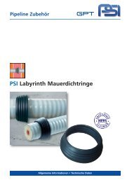
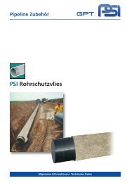
Pipeline Accessories<br />
<strong>PSI</strong> <strong>Plastic</strong> <strong>Insulators</strong><br />
System<br />
General Information • Technical Data • Selection Guide<br />
© 2012 <strong>PSI</strong> <strong>Products</strong> <strong>GmbH</strong> · Ulrichstraße 25 · D-72116 Mössingen · Phone +49 (0) 7473/37 81-0 · Fax +49 (0) 7473/37 81-35<br />
E-Mail vertrieb@psi-products.de 1 · www.psi-products.de
<strong>PSI</strong> <strong>Plastic</strong> <strong>Insulators</strong> System<br />
Material Test Certificate<br />
© 2012 <strong>PSI</strong> <strong>Products</strong> <strong>GmbH</strong> · Ulrichstraße 25 · D-72116 Mössingen · Phone +49 (0) 7473/37 81-0 · Fax +49 (0) 7473/37 81-35<br />
E-Mail vertrieb@psi-products.de · www.psi-products.de
<strong>PSI</strong> <strong>Plastic</strong> <strong>Insulators</strong> System<br />
General Information<br />
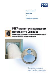
Polypropylen insulators are universally applicable in the installation of pipelines<br />
when the carrier pipe runs inside a casing.<br />
<strong>Plastic</strong> insulators provide various advantages:<br />
– easy installation of the carrier pipe since the plastic material reduces<br />
the friction coefficient to a minimum<br />
– minimised friction prevents damage to the protective coating and<br />
insulation of the pipes<br />
– a wide range of skid heights ensures concentricity of the carrier pipe in<br />
the casing if required<br />
– excellent insulating properties of the plastic material ensures:<br />
all requirement of cathodic protection are met.<br />
<strong>Plastic</strong> insulators are suitable for all pipe diameters from 25 mm upwards and<br />
many skid heights are available to suit specific requirements.<br />
© 2012 <strong>PSI</strong> <strong>Products</strong> <strong>GmbH</strong> · Ulrichstraße 25 · D-72116 Mössingen · Phone +49 (0) 7473/37 81-0 · Fax +49 (0) 7473/37 81-35<br />
E-Mail vertrieb@psi-products.de · www.psi-products.de
<strong>PSI</strong> <strong>Plastic</strong> <strong>Insulators</strong> System<br />
Technical Data<br />
Material<br />
Polypropylene have a good friction coefficient due to steel wax like surface.<br />
The sliding friction coefficient is approx. 0.2 as for steel has a coefficient of<br />
approx. 0.5. Therefore the abrasion is reduced to a minimum.<br />
The material is strong and yet flexible and is therefore resistant to stress<br />
cracking.<br />
Flexibility of the body, stability of the skid form and excellent dielectric<br />
insulation are some of the good characteristics of this material.<br />
Installation<br />
<strong>Plastic</strong> insulator rings are normally installed with the following spacing<br />
between the rings:<br />
- pipe dia up to 300 mm at a spacing of 2.5 m<br />
- pipe dia 400 – 600 mm at a spacing of 2.0 m<br />
- pipe dia > 600 mm at a spacing of 1.5 m<br />
In particular cases, the ring distance may be modified after having examined<br />
the installation situation.<br />
Load capacity:<br />
Typ<br />
PA/PE 0.75 – PA/PE 1.5<br />
PA/PE 2.0 – PA/PE 3.0<br />
PA/PE 4.0<br />
PA/PE 6.0 – PA/PE 12.0<br />
AZ/AC 1 / AZ/AC 2<br />
GKO-mK<br />
MA<br />
RGV<br />
GKO-gl<br />
GKO-gs<br />
max. static capacity per ring<br />
85 kg<br />
100 kg<br />
200 kg<br />
250 kg<br />
200 kg<br />
250 kg<br />
650 kg<br />
1,000 kg<br />
4,000 kg<br />
14,200 kg<br />
The weight load data apply to a skid height of up to 75 mm. For skid<br />
heights above 75 mm, these values have to be multiplied with the<br />
factor 0.75.<br />
All values are calculated for standard pipes. To determine the correct<br />
distance for your individual application many other facts have to be taken<br />
into consideration such as wall thickness of the carrier pipe, fluid to be<br />
transported… If you need any assistance please contact us.<br />
If you cannot determine the type according to our tables, please specify:<br />
– the O.D. of the carrier pipe (inclusive coating) in mm<br />
– the I.D. of the casing in mm<br />
© 2012 <strong>PSI</strong> <strong>Products</strong> <strong>GmbH</strong> · Ulrichstraße 25 · D-72116 Mössingen · Phone +49 (0) 7473/37 81-0 · Fax +49 (0) 7473/37 81-35<br />
E-Mail vertrieb@psi-products.de · www.psi-products.de
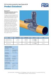
<strong>PSI</strong> <strong>Plastic</strong> Insulator Ring Type PA/PE System<br />
General Information<br />
Pipe O.D. from 25 mm to 336 mm<br />
Type PA/PE insulator rings are available for a pipe O.D. from 25 to 336 mm.<br />
They consist of two halfshell-segments. The nuts and bolts required for<br />
assembly are included.<br />
The type code indicates the carrier pipe O.D. in inch and the skid height<br />
in mm (e.g. PA/PE 4-38 = carrier pipe 4", skid height 38 mm).<br />
The skid height is calculated from the difference in diameter of the carrier<br />
pipe and the casing. It is important to consider the actual dimensions,<br />
including coatings, rather than the nominal sizes.<br />
Example: - PE- coated carrier pipe ND 100<br />
- O.D. (117.9 x 5.2 mm)<br />
- Steel casing ND 200 (219.1 x 6.3)<br />
- I.D. 206.5 mm minus Carrier pipe O.D. 117.9 mm = 88.6<br />
- 88,6 : 2 = 44.3 mm skid height<br />
- Suitable type: PA/PE 4-38<br />
After determining the skid height, the next lower height is selected from<br />
the table (e.g. 44.3 mm, ideal skid height = 38 mm).<br />
The segments can be assembled with the corrosion protected steel bolts<br />
DIN 912 and nuts DIN 562 included.<br />
Up to type PA/PE 4 the insulator rings have 4 skids; from type PA/PE 6<br />
up to 6 skids are provided. The following table gives the technical details<br />
on available sizes, skid heights of the various types and carrier pipe<br />
diameters.<br />
© 2012 <strong>PSI</strong> <strong>Products</strong> <strong>GmbH</strong> · Ulrichstraße 25 · D-72116 Mössingen · Phone +49 (0) 7473/37 81-0 · Fax +49 (0) 7473/37 81-35<br />
E-Mail vertrieb@psi-products.de · www.psi-products.de
<strong>PSI</strong> <strong>Plastic</strong> Insulator Ring Type PA/PE System<br />
How to find the right type<br />
Nom. Pipe O.D. Type Skid height Width Number of Number of Bolts Art. no.<br />
width in mm PA/PE mm incl. mm Segments skids DIN 912<br />
mm Inch min. max. basic element number/size<br />
20 0.75 25.0 32.0 PA/PE 0.75-12.5 12.5 80 2 4 4 M 4 x 30<br />
PA/PE 0.75-21 21.0<br />
PA/PE 0.75-25 25.0<br />
PA/PE 0.75-36 36.0<br />
25 1.0 32.0 40.0 PA/PE 1-13 13.0 80 2 4 4 M 4 x 30<br />
PA/PE 1-19 19.0<br />
PA/PE 1-25 25..0<br />
PA/PE 1-34 34.0<br />
32 1.25 42.0 48.3 PA/PE 1.25-11 11.0 80 2 4 4 M 4 x 30<br />
PA/PE 1.25-17.6 17.6<br />
PA/PE 1.25-29 29.0<br />
PA/PE 1.25-40 40.0<br />
40 1.5 48.0 54.0 PA/PE 1.5-11 11.0 80 2 4 4 M 4 x 30<br />
PA/PE 1.5-14.5 14.5<br />
PA/PE 1.5-26.0 26.0<br />
PA/PE 1.5-36 36.0<br />
PA/PE 1.5-48 48.0<br />
PA/PE 1.5-70 70.0<br />
50 2.0 60.0 67.0 1) PA/PE 2-16 16.0 100 2 4 4 M 6 x 40<br />
PA/PE 2-25 25.0<br />
PA/PE 2-36 36.0<br />
PA/PE 2-48 48.0<br />
PA/PE 2-55 55.0<br />
PA/PE 2-70 70.0<br />
PA/PE 2-90 90.0<br />
PA/PE 2-110 110.0<br />
65 2.5 76.1 82.5 2) PA/PE 2.5-16 16.0 100 2 4 4 M 6 x 40<br />
PA/PE 2.5-25 25.0<br />
PA/PE 2.5-36 36.0<br />
PA/PE 2.5-48 48.0<br />
PA/PE 2.5-55 55.0<br />
PA/PE 2.5-70 70.0<br />
PA/PE 2.5-90 90.0<br />
PA/PE 2.5-105 105.0<br />
80 3.0 88.9 96.0 3) PA/PE 3-16 16.0 100 2 4 4 M 6 x 40<br />
PA/PE 3-25 25.0<br />
PA/PE 3-36 36.0<br />
PA/PE 3-48 48.0<br />
PA/PE 3-55 55.0<br />
PA/PE 3-70 70.0<br />
PA/PE 3-90 90.0<br />
100 4.0 106.6 120.0 4) PA/PE 4-16 16.0 130 2 4 4 M 6 x 55<br />
PA/PE 4-25 25.0<br />
PA/PE 4-38 38.0<br />
PA/PE 4-55 55.0<br />
PA/PE 4-75 75.0<br />
PA/PE 4-90 90.0<br />
125 See list for AZ/AC Ø 125 mm Type AZ/AC 1<br />
3-001-02400<br />
3-001-01001<br />
3-001-01002<br />
3-001-01003<br />
3-001-01004<br />
3-001-01005<br />
3-001-01006<br />
3-001-01007<br />
3-001-01008<br />
3-001-01009<br />
3-001-01010<br />
3-001-01011<br />
3-001-01069<br />
3-001-01012<br />
3-001-01013<br />
3-001-01014<br />
3-001-01015<br />
3-001-01039<br />
3-001-01016<br />
3-001-01017<br />
3-001-01018<br />
3-001-01019<br />
3-001-01085<br />
3-001-01086<br />
3-001-01087<br />
3-001-01088<br />
3-001-01020<br />
3-001-01021<br />
3-001-01022<br />
3-001-01023<br />
3-001-01095<br />
3-001-01096<br />
3-001-01097<br />
3-001-01098<br />
3-001-01024<br />
3-001-01025<br />
3-001-01026<br />
3-001-01027<br />
3-001-01100<br />
3-001-01101<br />
3-001-01102<br />
3-001-01028<br />
3-001-01029<br />
3-001-01030<br />
3-001-01031<br />
3-001-01032<br />
3-001-01033<br />
© 2012 <strong>PSI</strong> <strong>Products</strong> <strong>GmbH</strong> · Ulrichstraße 25 · D-72116 Mössingen · Phone +49 (0) 7473/37 81-0 · Fax +49 (0) 7473/37 81-35<br />
E-Mail vertrieb@psi-products.de · www.psi-products.de
<strong>PSI</strong> <strong>Plastic</strong> Insulator Ring Type PA/PE System<br />
How to find the right type<br />
Nom. Pipe O.D. Type Skid height Width Number of Number of Bolts Art. no.<br />
width in mm PA/PE mm incl. mm Segments skids DIN 912<br />
mm Inch min. max. basic element number/size<br />
150 6 160.0 178.0 PA/PE 6-16 16.0 130 2 6 4 M 6 x 70<br />
PA/PE 6-25 25.0<br />
PA/PE 6-36 36.0<br />
PA/PE 6-55 55.0<br />
PA/PE 6-75* 75.0 4<br />
PA/PE 6-90* 90.0<br />
200 193.7 210.0 PA/PE 7-16 16.0 175 2 6 4 M 6 x 70<br />
PA/PE 7-25 25.0<br />
PA/PE 7-36 36.0<br />
PA/PE 7-55 55.0<br />
PA/PE 7-75 75.0<br />
PA/PE 7-90 90.0<br />
PA/PE 7-110 110.0<br />
200 8 221.0 239.0 PA/PE 8-16 16.0 130 2 6 4 M 6 x 70<br />
PA/PE 8-25 25.0<br />
PA/PE 8-36 36..0<br />
PA/PE 8-55* 55.0 4<br />
PA/PE 8-75* 75.0<br />
PA/PE 8-90* 90.0<br />
250 244.5 260.0 PA/PE 9-16 16.0 175 2 6 4 M 6 x 70<br />
PA/PE 9-25 25.0<br />
PA/PE 9-36 36.0<br />
PA/PE 9-55 55.0<br />
PA/PE 9-75 75.0<br />
PA/PE 9-90 90.0<br />
PA/PE 9-110 110.0<br />
250 10 276.0 295. 0 PA/PE 10-16 16.0 130 2 6 4 M 6 x 70<br />
PA/PE 10-25 25.0<br />
PA/PE 10-36 36.0<br />
PA/PE 10-55* 55.0 4<br />
PA/PE 10-75* 75.0<br />
PA/PE 10-90* 90.0<br />
315 298.5 315.0 PA/PE 11-16 16.0 175 2 6 4 M 6 x 70<br />
PA/PE 11-25 25.0<br />
PA/PE 11-36 36.0<br />
PA/PE 11-55 55.0<br />
PA/PE 11-75 75.0<br />
PA/PE 11-90 90.0<br />
PA/PE 11-110 110.0<br />
300 12 326.0 336.0 PA/PE 12-18 18.0 130 2 6 4 M 6 x 70<br />
PA/PE 12-25 25.0<br />
PA/PE 12-36 36.0<br />
PA/PE 12-55* 55.0 4<br />
PA/PE 12-75* 75.0<br />
PA/PE 12-90* 90.0<br />
3-001-01036<br />
3-001-01037<br />
3-001-01038<br />
3-001-01040<br />
3-001-01041<br />
3-001-01042<br />
3-001-01110<br />
3-001-01111<br />
3-001-01112<br />
3-001-01113<br />
3-001-01114<br />
3-001-01115<br />
3-001-01116<br />
3-001-01043<br />
3-001-01044<br />
3-001-01045<br />
3-001-01046<br />
3-001-01047<br />
3-001-01048<br />
3-001-01120<br />
3-001-01121<br />
3-001-01122<br />
3-001-01123<br />
3-001-01124<br />
3-001-01125<br />
3-001-01126<br />
3-001-01049<br />
3-001-01050<br />
3-001-01051<br />
3-001-01052<br />
3-001-01053<br />
3-001-01054<br />
3-001-01130<br />
3-001-01131<br />
3-001-01132<br />
3-001-01133<br />
3-001-01134<br />
3-001-01135<br />
3-001-01136<br />
3-001-01055<br />
3-001-01056<br />
3-001-01057<br />
3-001-01058<br />
3-001-01059<br />
3-001-01060<br />
1) up to Pipe O.D. 75.0 mm with 4 Bolts M 6 x 55<br />
2) up to Pipe O.D. 88.9 mm with 4 Bolts M 6 x 55<br />
3) up to Pipe O.D. 101.6 mm with 4 Bolts M 6 x 55<br />
4) up to Pipe O.D. 127.0 mm with 4 Bolts M 6 x 70<br />
Shear-secure-tape against slipping of spacers see next page<br />
* Plug in skid<br />
Sectional drawing<br />
PA/PE 0.75 to PA/PE 4,<br />
ring with 4 skids total<br />
Sectional drawing<br />
PA/PE 6 to PA/PE 12,<br />
ring with 6 skids total<br />
© 2012 <strong>PSI</strong> <strong>Products</strong> <strong>GmbH</strong> · Ulrichstraße 25 · D-72116 Mössingen · Phone +49 (0) 7473/37 81-0 · Fax +49 (0) 7473/37 81-35<br />
E-Mail vertrieb@psi-products.de · www.psi-products.de
<strong>PSI</strong> <strong>Plastic</strong> Insulator Ring Type PA/PE System<br />
Accessories<br />
Shear-Secure-Tape<br />
Art.No. 4-002-S20088 = width 50 mm, length 15 m<br />
Art.No. 4-002-S20089 = width 100 mm, length 15 m<br />
Material: PE-Tape with butyl rubber mixture<br />
Application:<br />
On smooth pipe surface which are in contact with the spacers (e.g. PE, PVC,<br />
steel/cast on PE-coated or stoneware) wrap a shear-secure-tape to guarantee<br />
an optimum security against slipping.<br />
© 2012 <strong>PSI</strong> <strong>Products</strong> <strong>GmbH</strong> · Ulrichstraße 25 · D-72116 Mössingen · Phone +49 (0) 7473/37 81-0 · Fax +49 (0) 7473/37 81-35<br />
E-Mail vertrieb@psi-products.de · www.psi-products.de
<strong>PSI</strong> <strong>Plastic</strong> Insulator Ring Type PA/PE <strong>PSI</strong> System<br />
Installation Instruction<br />
An insulator ring always consists of two halves fitting the indicated pipe<br />
size. Four nuts and bolts per insulator ring are necessary.<br />
Wrap smooth pipe surfaces (e.g. PE, PVC, PE coated steel/cast iron or<br />
vitrified clay) in the pipe/insulator contact area with shear-secure-tape<br />
to guarantee utmost safety against slipping.<br />
Place the two halves around the pipe and join them with bolts. Then<br />
tighten the bolts evenly in order to get even distances between the<br />
insulator elements.<br />
The square nuts have to be aligned in a way to fit in the corresponding<br />
recesses of the insulator segment.<br />
Tighten the bolts so that the insulator ring is firmly attached to the pipe.<br />
It is not absolutely necessary to tighten the bolts completely.<br />
Max. torques:<br />
Insulator type PA/PE 0.75 - PA/PE 1.5 = 0.7 Nm<br />
Insulator type PA/PE 2 - PA/PE 12 = 3 Nm<br />
© 2012 <strong>PSI</strong> <strong>Products</strong> <strong>GmbH</strong> · Ulrichstraße 25 · D-72116 Mössingen · Phone +49 (0) 7473/37 81-0 · Fax +49 (0) 7473/37 81-35<br />
E-Mail vertrieb@psi-products.de · www.psi-products.de
<strong>PSI</strong> <strong>Plastic</strong> Insulator Segments Type AZ/AC System<br />
General Information<br />
Pipe O.D. from 98 mm to 385 mm<br />
AZ/AC insulator rings are used for a pipe O.D. from 98 to 385 mm and<br />
consist of several segments. The number of segments depends on the<br />
carrier pipe's O.D.. The nuts and bolts required for assembly are included.<br />
The universal applicability of type AZ/AC provides two special advantages:<br />
– variable ring diameter, which is especially important for thick-walled<br />
pipes whose O.D. substantially deviates from the nominal size<br />
(e.g. AZ/AC pressure pipe ND 16, vitrified clay pipes);<br />
– only two segment sizes are required to assemble ND 100 to ND 350<br />
insulator rings - a decisive edge in stock-keeping.<br />
The skid height is calculated from the difference in diameter of the carrier<br />
pipe and the casing. It is important to consider the actual dimensions,<br />
including coatings, rather than the nominal sizes.<br />
For an example calculation refer to type PA/PE.<br />
The segmenst can be assembled with the corrosion protected steel bolts<br />
DIN 912 and nuts DIN 562 included.<br />
The following table gives the technical details on available sizes, skid<br />
heights of the various types and carrier pipe diameters.<br />
Sectional drawing of AZ/AC 1 segment<br />
Sectional drawing of AZ/AC 2 segment<br />
© 2012 <strong>PSI</strong> <strong>Products</strong> <strong>GmbH</strong> · Ulrichstraße 25 · D-72116 Mössingen · Phone +49 (0) 7473/37 81-0 · Fax +49 (0) 7473/37 81-35<br />
E-Mail vertrieb@psi-products.de · www.psi-products.de
<strong>PSI</strong> <strong>Plastic</strong> Insulator Segments Type AZ/AC System<br />
How to find the right type<br />
Type Skid height Width Number of bolts per segment Article no.<br />
AZ/AC-1 16 130 2 M6 x 70 3-002-00085<br />
AZ/AC-1 25 130 2 M6 x 70 3-002-00086<br />
AZ/AC-1 36 130 2 M6 x 70 3-002-00087<br />
AZ/AC-1 55 130 2 M6 x 70 3-002-00088<br />
AZ/AC-1 75 130 2 M6 x 70 3-002-00089<br />
AZ/AC-1 90 130 2 M6 x 70 3-002-00083<br />
AZ/AC-1 110 130 2 M6 x 70 3-002-00097<br />
AZ/AC-2 16 130 2 M6 x 70 3-002-00090<br />
AZ/AC-2 25 130 2 M6 x 70 3-002-00091<br />
AZ/AC-2 36 130 2 M6 x 70 3-002-00092<br />
AZ/AC-2 55 130 2 M6 x 70 3-002-00093<br />
AZ/AC-2 75 130 2 M6 x 70 3-002-00094<br />
AZ/AC-2 90 130 2 M6 x 70 3-002-00095<br />
AZ/AC-2 110 130 2 M6 x 70 3-002-00096<br />
Shear-secure-tape, 15 m/roll, 50 mm width<br />
4-002-S20088<br />
Outer Ø of carrier pipe in mm Number of segments per ring Bolts number/size<br />
min. max. AZ/AC 1 AZ/AC 2<br />
98 130 3 6 M 6x70<br />
130 172 4 8 M 6x70<br />
173 202 5 10 M 6x70<br />
203 230 3 6 M 6x70<br />
234 268 1 3 8 M 6x70<br />
269 310 4 8 M 6x70<br />
302 350 1 4 10 M 6x70<br />
350 385 5 10 M 6x70<br />
Shear-Secure-Tape<br />
Art.No. 4-002-S20088 = width 50 mm, length 15 m<br />
Art.No. 4-002-S20089 = width 100 mm, length 15 m<br />
Material: PE-Tape with butyl rubber mixture<br />
Application:<br />
On smooth pipe surface which are in contact with<br />
the spacers (e.g. PE, PVC, steel/cast on PE-coated<br />
or stoneware) wrap a shear-secure-tape to guarantee<br />
an optimum security against slipping.<br />
© 2012 <strong>PSI</strong> <strong>Products</strong> <strong>GmbH</strong> · Ulrichstraße 25 · D-72116 Mössingen · Phone +49 (0) 7473/37 81-0 · Fax +49 (0) 7473/37 81-35<br />
E-Mail vertrieb@psi-products.de · www.psi-products.de
<strong>PSI</strong> <strong>Plastic</strong> Insulator Segments Type AZ/AC System<br />
Installation Instruction<br />
Get insulator elements and bolts ready according to the selection table<br />
(see reverse).<br />
Join the elements in a insulator band and tighten the nuts just a few turns<br />
on the bolts.<br />
Wrap smooth pipe surfaces (e.g. PE, PVC, PE coated steel/cast iron or<br />
vitrified clay) in the pipe/ insulator contact area with shear-secure-tape<br />
to guarantee utmost safety against slipping.<br />
Place pre-assembled elements around the carrier pipe and close the final<br />
segments.<br />
Then tighten the bolts evenly in order to get even distances between the<br />
insulator elements.<br />
The square nuts have to be aligned in a way to fit in the corresponding<br />
recesses of the insulator segment.<br />
Tighten the bolts with a torque of no more than 3 Nm so that the insulator<br />
ring is firmly attached to the pipe. It is not absolutely necessary to tighten<br />
the bolts completely.<br />
© 2012 <strong>PSI</strong> <strong>Products</strong> <strong>GmbH</strong> · Ulrichstraße 25 · D-72116 Mössingen · Phone +49 (0) 7473/37 81-0 · Fax +49 (0) 7473/37 81-35<br />
E-Mail vertrieb@psi-products.de · www.psi-products.de
<strong>PSI</strong> <strong>Plastic</strong> Insulator Type GKO-mk System<br />
General Information<br />
GKO-mk are the latest <strong>PSI</strong> Insulator generation. Due to the bolt less wedge system<br />
the installation can be achieved quick and easy. The flexible design ensures suitablity<br />
for all pipe diameters > 150 mm.<br />
If required an additional support for cable ducts can be installed on the segment.<br />
• Flexible construction<br />
• Non-metallic connection for simple and fast installation<br />
• Connection technology by wedge system<br />
<strong>PSI</strong> shear-secure-tapes can be used to improve adhesion on smooth<br />
surfaces or to balance tolerances.<br />
Subject to technical changes.<br />
© 2012 <strong>PSI</strong> <strong>Products</strong> <strong>GmbH</strong> · Ulrichstraße 25 · D-72116 Mössingen · Phone +49 (0) 7473/37 81-0 · Fax +49 (0) 7473/37 81-35<br />
E-Mail vertrieb@psi-products.de · www.psi-products.de
<strong>PSI</strong> <strong>Plastic</strong> Insulator Type GKO-mk System<br />
How to find the right type<br />
Type Skid height Width Article no.<br />
GKO mk 25 130 3-002-04101<br />
GKO mk 36 130 3-002-04102<br />
GKO mk 50 130 3-002-04103<br />
GKO mk 65 130 3-002-04104<br />
GKO mk 75 130 3-002-04105<br />
GKO mk 90 130 3-002-04106<br />
GKO mk 110 130 3-002-04107<br />
GKO mk 125 130 3-002-04108<br />
Shear-secure-tape, 15 m/roll, 50 mm width<br />
4-002-S20088<br />
Outer Ø of carrier pipe in mm<br />
Number of segments<br />
per ring<br />
min.<br />
max.<br />
150 180 4<br />
181 230 5<br />
231 280 6<br />
281* 330* 7<br />
331* 380* 8<br />
381* 430* 9<br />
* carrier pipe O.D. exceeding 281 mm only appropriate for plastic tubes<br />
Material: PE-Tape with butyl rubber mixture<br />
Shear-Secure-Tape<br />
Art.No. 4-002-S20088 = width 50 mm, length 15 m<br />
Art.No. 4-002-S20089 = width 100 mm, length 15 m<br />
Application:<br />
On smooth pipe surface which are in contact<br />
with the spacers (e.g. PE, PVC, steel/cast on<br />
PE-coated or stoneware) wrap a shear-securetape<br />
to guarantee an optimum security<br />
against slipping.<br />
© 2012 <strong>PSI</strong> <strong>Products</strong> <strong>GmbH</strong> · Ulrichstraße 25 · D-72116 Mössingen · Phone +49 (0) 7473/37 81-0 · Fax +49 (0) 7473/37 81-35<br />
E-Mail vertrieb@psi-products.de · www.psi-products.de
<strong>PSI</strong> <strong>Plastic</strong> Insulator Type GKO-mk System<br />
Installation Instruction<br />
Put out spacer elements and wedges according to selection table.<br />
Connect elements as a spacer band (for position of the wedges per spacer<br />
element see selection table on the backside), put the mounting link with grid into<br />
the entry of next element, be aware of parallelism. Push wedges into the lateral<br />
fixing slot until top can be seen on the other side of the spacer.<br />
Mind the direction of the arrows.<br />
On smooth pipe surface which are in contact with the spacers (e.g. PE, PVC,<br />
steel/cast on PE-coated or stoneware) wrap a shear-secure-tape to guarantee an<br />
optimum security against slipping.<br />
Put pre-mounted elements around the medium pipe and close last joint. Shift the<br />
spacer ring together by hand.<br />
Shift spacer elements together with a screw clamp as far that one or more<br />
wedges can be put in the next fixing slot.<br />
Drive in all wedges with hammer strokes parallel to the pipe. The wedges don’t<br />
have to be in fully.<br />
When mounting more spacer rings please be aware that the skids of the single<br />
mounted rings align together.<br />
We expressly exclude any other use of the material. The <strong>PSI</strong> guarantee<br />
is restricted to faulty material. The suitability of the product for a special<br />
purpose must be tested by the user on his own responsibility.<br />
© 2012 <strong>PSI</strong> <strong>Products</strong> <strong>GmbH</strong> · Ulrichstraße 25 · D-72116 Mössingen · Phone +49 (0) 7473/37 81-0 · Fax +49 (0) 7473/37 81-35<br />
E-Mail vertrieb@psi-products.de · www.psi-products.de
<strong>PSI</strong> <strong>Plastic</strong> Insulator Type GKO-mk System<br />
Installation Instruction<br />
Pipe ND Pipe O.D. number per segment Position of wedges<br />
in mm<br />
in connecting section<br />
PE Steel GGG up to GKO mk 1 2 3<br />
DN 150 160 164 4 0 2 2<br />
DN 150 180 183 4 1 2 1<br />
DN 150 174 176 4 0 4 0<br />
DN 150 170 175 4 1 1 2<br />
DN 200 200 204 5 0 2 3<br />
DN 200 225 230 5 1 4 0<br />
DN 200 250 255 6 0 4 2<br />
DN 200 224 227 5 1 3 1<br />
DN 200 222 226 5 1 3 1<br />
DN 250 280 285 6 3 2 1<br />
DN 250 279 283 6 3 2 1<br />
DN 250 274 278 6 3 1 2<br />
DN 300 315 318 7 1 5 1<br />
DN 350 355 358 8 0 8 0<br />
DN 400 400 405 9 0 9 0<br />
The recommended position of the wedges are<br />
experienced and can differ acc. to outside<br />
temperature.<br />
GKO mounting example:<br />
For a pipe OD 200 mm, use 5 elements<br />
per ring. Put 2 wedge in position 2<br />
and 3 wedges in position 3.<br />
© 2012 <strong>PSI</strong> <strong>Products</strong> <strong>GmbH</strong> · Ulrichstraße 25 · D-72116 Mössingen · Phone +49 (0) 7473/37 81-0 · Fax +49 (0) 7473/37 81-35<br />
E-Mail vertrieb@psi-products.de · www.psi-products.de
<strong>PSI</strong> <strong>Plastic</strong> Insulator Type GKO-gl and GKO-gs System<br />
General Information<br />
GKO gs and GKO gl are the latest <strong>PSI</strong> Insulator generation. Due to the<br />
bolt less wedge system and half segments GKO the installation can be<br />
achieved easily and quickly.<br />
Owing to various diameter ranges and type GKO gh half segments, continnous<br />
use for an outer diameter exceeding 400 mm is possible.<br />
If required an additional support for cable ducts can be with cable binders<br />
fixed on the segment.<br />
• Flexible construction<br />
• Non-metallic connection for simple and fast installation<br />
• Connection technology by wedge system<br />
<strong>PSI</strong> shear-secure-tapes can be used to improve adhesion on smooth<br />
surfaces or to balance tolerances.<br />
Subject to technical changes.<br />
© 2012 <strong>PSI</strong> <strong>Products</strong> <strong>GmbH</strong> · Ulrichstraße 25 · D-72116 Mössingen · Phone +49 (0) 7473/37 81-0 · Fax +49 (0) 7473/37 81-35<br />
E-Mail vertrieb@psi-products.de · www.psi-products.de
<strong>PSI</strong> <strong>Plastic</strong> Insulator Type GKO-gl and GKO-gs System<br />
How to find the right type<br />
Type Skid height Width Article no.<br />
GKO gl 36 225 3-002-02200<br />
GKO gl 50 225 3-002-02201<br />
GKO gl 65 225 3-002-02202<br />
GKO gl 75 225 3-002-02203<br />
GKO gl 90 225 3-002-02204<br />
GKO gl 110 225 3-002-02205<br />
GKO gl 125 225 3-002-02206<br />
GKO-gl<br />
GKO gs 36 225 3-003-03207<br />
GKO gs 50 225 3-003-03208<br />
GKO gs 65 225 3-003-03209<br />
GKO gs 75 225 3-003-03210<br />
GKO gs 90 225 3-003-03211<br />
GKO gs 110 225 3-003-03212<br />
GKO gs 125 225 3-003-03213<br />
GKO gh 36 225 3-003-03200<br />
GKO gh 50 225 3-003-03201<br />
GKO gh 65 225 3-003-03202<br />
GKO gh 75 225 3-003-03203<br />
GKO gh 90 225 3-003-03204<br />
GKO gh 110 225 3-003-03205<br />
GKO gh 125 225 3-003-03206<br />
Shear-Secure-Tape against slipping see below<br />
GKO-gs<br />
GKO-gh<br />
Outer Ø of carrier pipe in mm<br />
Number of segments per ring<br />
min. max. GKO gl/gs GKO gh<br />
400<br />
441<br />
440<br />
490<br />
3<br />
4<br />
1<br />
491 540 4 1<br />
541 625 5<br />
626 659 5 1<br />
660 749 6<br />
750 854 7<br />
855 959 8<br />
960 1067 9<br />
1068 1199 10<br />
1200 1330 11<br />
1331 1440 12<br />
1441 1540 13<br />
1541 1660 14<br />
1661 1800 15<br />
1801 1910 16<br />
1911 2042 17<br />
2043 2150 18<br />
2151 2270 19<br />
2271 2400 20<br />
2401 2500 21<br />
Material: PE-Tape with butyl rubber mixture<br />
Shear-Secure-Tape<br />
Art.No. 4-002-S20088 = width 50 mm, length 15 m<br />
Art.No. 4-002-S20089 = width 100 mm, length 15 m<br />
Application:<br />
On smooth pipe surface which are in contact with the spacers (e.g. PE,<br />
PVC, steel/cast on PE-coated or stoneware) wrap a shear-secure-tape<br />
to guarantee an optimum security against slipping.<br />
© 2012 <strong>PSI</strong> <strong>Products</strong> <strong>GmbH</strong> · Ulrichstraße 25 · D-72116 Mössingen · Phone +49 (0) 7473/37 81-0 · Fax +49 (0) 7473/37 81-35<br />
E-Mail vertrieb@psi-products.de · www.psi-products.de
<strong>PSI</strong> <strong>Plastic</strong> Insulator Type GKO-gl and GKO-gs System<br />
Installation Instruction<br />
Put out spacer<br />
elements and<br />
wedges according<br />
to selection table.<br />
Connect elements as<br />
a spacer band (for position<br />
of the wedges per spacer element<br />
see selection table on the<br />
backside), put the mounting link<br />
with grid into the entry of next element,<br />
be aware of parallelism. Push wedges<br />
into the lateral fixing slot until top can be<br />
seen on the other side of the spacer. Mind<br />
the direction of the arrows.<br />
On smooth pipe surface which are in contact with the spacers (e.g. PE, PVC,<br />
steel/cast on PE-coated or stoneware) wrap a shear-secure-tape to guarantee an<br />
optimum security against slipping.<br />
Put pre-mounted elements around the medium pipe and close last joint. Shift the<br />
spacer ring together by hand.<br />
Shift spacer elements together with a screw clamp as far that one or more<br />
wedges can be put in the next fixing slot.<br />
Drive in all wedges with hammer strokes parallel to the pipe. The wedges don’t<br />
have to be in fully.<br />
Attention:<br />
The lashes of the smaller pipe diameters (ND400 – 600) have to be slightly bent<br />
downwards for an easier insertion.<br />
When mounting more spacer rings please be aware that the skids of the single<br />
mounted rings align together.<br />
We expressly exclude any other use of the material. The <strong>PSI</strong> guarantee<br />
is restricted to faulty material. The suitability of the product for a special<br />
purpose must be tested by the user on his own responsibility.<br />
© 2012 <strong>PSI</strong> <strong>Products</strong> <strong>GmbH</strong> · Ulrichstraße 25 · D-72116 Mössingen · Phone +49 (0) 7473/37 81-0 · Fax +49 (0) 7473/37 81-35<br />
E-Mail vertrieb@psi-products.de · www.psi-products.de
<strong>PSI</strong> <strong>Plastic</strong> Insulator Type GKO-gl and GKO-gs System<br />
Installation Instruction<br />
Pipe ND Pipe O.D. number of elements Position of wedges<br />
in mm per ring in connecting section<br />
PE Steel GGG up to GKO GKO half seg. 1 2 3 4<br />
ND 400 397 402 3 1 3 1<br />
ND 400 406 411 3 1 1 3<br />
ND 400 429 439 3 1 1 3<br />
ND 450 448 452 4 3 1<br />
456 462 4 1 3<br />
ND 500 498 504 4 1 2 3<br />
ND 500 508 513 4 1 4 1<br />
ND 500 532 542 4 1 3 2<br />
538 542 5 5<br />
559 564 5 4 1<br />
ND 600 610 615 5 2 3<br />
ND 600 630 635 5 1 6<br />
ND 600 635 645 5 1 1 5<br />
660 665 6 3 3<br />
ND 700 711 716 6 5 1<br />
ND 700 738 748 6 4 2<br />
762 767 7 2 5<br />
ND 800 796 802 7 7<br />
ND 800 813 819 7 3 4<br />
ND 800 842 852 7 1 6<br />
864 870 8 1 7<br />
ND 900 914 920 8 1 7<br />
ND 900 945 955 8 6 2<br />
ND 1000 1016 1022 9 7 2<br />
ND 1000 1048 1058 9 4 5<br />
1057 1063 9 6 3<br />
1118 1125 10 6 4<br />
ND 1200 1219 1226 11 6 5<br />
1321 1328 11 1 10<br />
ND 1400 1422 1430 12 9 3<br />
1524 1532 13 7 6<br />
ND 1600 1626 1634 14 5 9<br />
1727 1736 15 3 12<br />
ND 1800 1829 1838 16 1 15<br />
1930 1939 17 16 1<br />
ND 2000 2032 2041 17 16 1<br />
2134 2144 18 14 4<br />
ND 2200 2235 2245 19 12 7<br />
2337 2347 20 10 10<br />
ND 2400 2438 2448 21 8 13<br />
The recommended position of the wedges<br />
are experienced and can differ according to<br />
outside temperature.<br />
GKO mounting example:<br />
For a pipe O.D. 429 mm, use 3 full and 1 half<br />
element per ring. Put 1 wedge in position 1<br />
and 3 wedges in position 2. 1<br />
2<br />
3<br />
4<br />
© 2012 <strong>PSI</strong> <strong>Products</strong> <strong>GmbH</strong> · Ulrichstraße 25 · D-72116 Mössingen · Phone +49 (0) 7473/37 81-0 · Fax +49 (0) 7473/37 81-35<br />
E-Mail vertrieb@psi-products.de · www.psi-products.de
<strong>PSI</strong> <strong>Plastic</strong> Insulator Segment Type MA System<br />
General Information<br />
Pipe O.D. from 402 mm up<br />
Starting with a pipe O.D. of 402 mm, MA insulator rings consisting of two<br />
segment sizes (MA and MA2) and various skid heights are used to suit the<br />
respective pipe O.D.<br />
The special advantage of these insulators is their universal applicability.<br />
The following rule is used to determine the composition of suitable insulator<br />
rings:<br />
– for every 100 mm of pipe O.D. = 1 MA segment<br />
– for every 50 mm of pipe O.D. = 1 MA 2 segment<br />
Example: Carrier pipe O.D. 559 = 5 MA segments + 1 MA 2 segment.<br />
The segment's skid height is calculated from the difference in diameter of<br />
the carrier pipe and the casing.<br />
For an example calculation refer to type PA/PE.<br />
The nuts and bolts required for assembly are included.<br />
The following table gives the technical details on available sizes, skid heights<br />
of the various types and carrier pipe diameters.<br />
© 2012 <strong>PSI</strong> <strong>Products</strong> <strong>GmbH</strong> · Ulrichstraße 25 · D-72116 Mössingen · Phone +49 (0) 7473/37 81-0 · Fax +49 (0) 7473/37 81-35<br />
E-Mail vertrieb@psi-products.de · www.psi-products.de
<strong>PSI</strong> <strong>Plastic</strong> Insulator Segment Type MA System<br />
How to find the right type<br />
Type Skid height Width Number of Number of bolts Art. no.<br />
mm mm skids per segment<br />
MA 25 25 160 3 2 M 8 x 70 3-002-00050<br />
MA 36 36 160 3 2 M 8 x 70 3-002-00051<br />
MA 50 50 160 3 2 M 8 x 70 3-002-00053<br />
MA 65 65 160 3 2 M 8 x 70 3-002-00064<br />
MA 75 75 160 3 2 M 8 x 70 3-002-00054<br />
MA 2/25 25 160 2 2 M 8 x 70 3-002-00055<br />
MA 2/36 36 160 2 2 M 8 x 70 3-002-00056<br />
MA 2/50 50 160 2 2 M 8 x 70 3-002-00057<br />
MA 2/65 65 160 2 2 M 8 x 70 3-002-00063<br />
MA 2/75 75 160 2 2 M 8 x 70 3-002-00058<br />
MA 2 = half segment<br />
Shear-Secure-Tape against slipping see below<br />
Nominal<br />
diameter<br />
Outer Ø of<br />
carrier pipe<br />
in mm<br />
Number of<br />
segments<br />
per ring<br />
ND inch min. max. MA 1 MA 2<br />
Bolts<br />
number/size<br />
400 16 402 435 4 8 M 8x70<br />
450 18 450 494 4 1 10 M 8x70<br />
500 20 500 544 5 10 M 8x70<br />
550 22 548 599 5 1 12 M 8x70<br />
600 24 600 653 6 12 M 8x70<br />
650 26 654 699 6 1 14 M 8x70<br />
700 28 700 749 7 14 M 8x70<br />
750 30 750 799 7 1 16 M 8x70<br />
800 32 800 849 8 16 M 8x70<br />
850 34 850 899 8 1 18 M 8x70<br />
900 36 900 949 9 18 M 8x70<br />
950 38 950 994 9 1 20 M 8x70<br />
1000 40 995 1044 10 20 M 8x70<br />
1050 42 1045 1097 10 1 22 M 8x70<br />
1100 44 1098 1149 11 22 M 8x70<br />
1150 46 1150 1199 11 1 24 M 8x70<br />
1200 48 1200 1306 12 24 M 8x70<br />
Sectional drawing of MA segment<br />
Sectional drawing of MA 2 segment<br />
For larger nominal diameter on request.<br />
Material: PE-Tape with butyl rubber mixture<br />
Shear-Secure-Tape<br />
Art.No. 4-002-S20088 = width 50 mm, length 15 m<br />
Art.No. 4-002-S20089 = width 100 mm, length 15 m<br />
Application:<br />
On smooth pipe surface which are in contact<br />
with the spacers (e.g. PE, PVC, steel/cast on<br />
PE-coated or stoneware) wrap a shear-securetape<br />
to guarantee an optimum security<br />
against slipping.<br />
© 2012 <strong>PSI</strong> <strong>Products</strong> <strong>GmbH</strong> · Ulrichstraße 25 · D-72116 Mössingen · Phone +49 (0) 7473/37 81-0 · Fax +49 (0) 7473/37 81-35<br />
E-Mail vertrieb@psi-products.de · www.psi-products.de
<strong>PSI</strong> <strong>Plastic</strong> Insulator Segment Type RGV System<br />
General Information<br />
For heavy pipes from pipe O.D. 500 mm up<br />
RGV insulator rings are used from a pipe O.D. of 500 mm. They differ from<br />
MA types in having two reinforced load-carrying centre solid skids per<br />
segment. The fastening skids (36 mm high) are for connection only. To<br />
obtain the required pipe O.D., RGV segments are combined with RGV 2<br />
segments.<br />
Special advantages of these insulator rings are their high static load-carrying<br />
capacity and their versatility. The following rule is used to determine the<br />
composition of suitable insulator rings:<br />
– for every 100 mm of pipe O.D. = 1 RGV segment<br />
– for every 50 mm of pipe O.D. = 1 RGV 2 segment<br />
Example:<br />
Carrier pipe O.D. 559 = 5 RGV segments RGV + 1 RGV 2 segment<br />
The segment's skid height is calculated from the difference in diameter of<br />
the carrier pipe and the casing.<br />
For an example calculation refer to type PA/PE.<br />
The nuts and bolts required for assembly are included.<br />
The following table gives the technical details on available sizes, skid heights<br />
of the various types and carrier pipe diameters.<br />
© 2012 <strong>PSI</strong> <strong>Products</strong> <strong>GmbH</strong> · Ulrichstraße 25 · D-72116 Mössingen · Phone +49 (0) 7473/37 81-0 · Fax +49 (0) 7473/37 81-35<br />
E-Mail vertrieb@psi-products.de · www.psi-products.de
<strong>PSI</strong> <strong>Plastic</strong> Insulator Segment Type RGV System<br />
How to find the right type<br />
Type Skid heigth Width Number of bolts Art. no.<br />
mm mm<br />
RGV 50 210 2 M 8x70 3-002-00074<br />
RGV 75 210 2 M 8x70 3-002-00075<br />
RGV 90 210 2 M 8x70 3-002-00076<br />
RGV 125 210 2 M 8x70 3-002-00073<br />
RGV half 50 210 2 M 8x70 3-002-00274<br />
RGV half 75 210 2 M 8x70 3-002-00275<br />
RGV half 90 210 2 M 8x70 3-002-00276<br />
RGV half 125 210 2 M 8x70 3-002-00273<br />
Shear-Secure-Tape against slipping see below<br />
Nominal Pipe O.D. Number Bolts<br />
diameter in mm of segments number/size<br />
DN Zoll min. max. RGV RGV half<br />
500 20 500 535 5 10 M 8 x 70<br />
550 22 547 595 5 1 12 M 8 x 70<br />
600 24 596 645 6 12 M 8 x 70<br />
650 26 646 699 6 1 14 M 8 x 70<br />
700 28 700 750 7 14 M 8 x 70<br />
750 30 751 799 7 1 16 M 8 x 70<br />
800 32 800 850 8 16 M 8 x 70<br />
850 34 851 899 8 1 18 M 8 x 70<br />
900 36 900 950 9 18 M 8 x 70<br />
950 38 951 999 9 1 20 M 8 x 70<br />
1000 40 1000 1075 10 20 M 8 x 70<br />
1100 44 1090 1180 11 22 M 8 x 70<br />
1200 48 1190 1290 12 24 M 8 x 70<br />
1300 52 1291 1390 13 26 M 8 x 70<br />
1400 56 1391 1490 14 28 M 8 x 70<br />
1500 60 1491 1590 15 30 M 8 x 70<br />
1600 64 1591 1690 16 32 M 8 x 70<br />
1700 68 1691 1790 17 34 M 8 x 70<br />
1800 72 1791 1890 18 36 M 8 x 70<br />
1900 76 1891 1990 19 38 M 8 x 70<br />
2000 80 1991 2100 20 40 M 8 x 70<br />
Sectional drawing of RGV segment<br />
For larger nominal diameter on request.<br />
Material: PE-Tape with butyl rubber mixture<br />
Shear-Secure-Tape<br />
Art.No. 4-002-S20088 = width 50 mm, length 15 m<br />
Art.No. 4-002-S20089 = width 100 mm, length 15 m<br />
Application:<br />
On smooth pipe surface which are in contact with the spacers<br />
(e.g. PE, PVC, steel/cast on PE-coated or stoneware) wrap a<br />
shear-secure-tape to guarantee an optimum security against<br />
slipping.<br />
© 2012 <strong>PSI</strong> <strong>Products</strong> <strong>GmbH</strong> · Ulrichstraße 25 · D-72116 Mössingen · Phone +49 (0) 7473/37 81-0 · Fax +49 (0) 7473/37 81-35<br />
E-Mail vertrieb@psi-products.de · www.psi-products.de
<strong>PSI</strong> <strong>Plastic</strong> <strong>Insulators</strong> Type MA and Type RGV System<br />
Installation Instructions<br />
Put out elements of spacers and<br />
screws according to selection table<br />
(type MA respectively type RGV).<br />
Connect elements as a spacer band<br />
and fix the nuts on the screws with<br />
just a few rotations.<br />
On smooth pipe surfaces (e.g. PE, PVC, steel/cast on PE-coated or stoneware)<br />
wrap a shear-secure-tape to guarantee an optimum security against slipping.<br />
Put pre-mounted elements around the medium pipe and close last joint.<br />
Draw the screws equally tight to receive equal pitches between the spacer elements.<br />
Square nuts have to fit into the designed cavity of the spacer segment.<br />
Tighten screws with a torque moment of max. 8 Nm to fix the spacer ring irremovable<br />
on the pipe. Screws don’t have to be necessarily completely contracted.<br />
Outer diameter<br />
of the medium<br />
pipe in mm<br />
Number of<br />
segments<br />
per ring<br />
from up RGV RGV half<br />
500 - 535 5<br />
547 - 595 5 1<br />
596 - 645 6<br />
646 - 699 6 1<br />
700 - 750 7<br />
751 - 799 7 1<br />
800 - 850 8<br />
851 - 899 8 1<br />
900 - 950 9<br />
951 - 999 9 1<br />
1000 - 1075 10<br />
1090 - 1180 11<br />
1190 - 1290 12<br />
1291 - 1390 13<br />
1391 - 1490 14<br />
1491 - 1590 15<br />
1591 - 1690 16<br />
1691 - 1790 17<br />
1791 - 1890 18<br />
1891 - 1990 19<br />
1991 - 2100 20<br />
Outer diameter<br />
of the medium<br />
pipe in mm<br />
Number of<br />
segments<br />
per ring<br />
from up MA MA 2<br />
402 - 435 4<br />
450 - 494 4 1<br />
500 - 544 5<br />
548 - 599 5 1<br />
600 - 653 6<br />
654 - 699 6 1<br />
700 - 749 7<br />
750 - 799 7 1<br />
800 - 849 8<br />
850 - 899 8 1<br />
900 - 949 9<br />
950 - 994 9 1<br />
995 -1044 10<br />
1045 - 1097 10 1<br />
1098 - 1149 11<br />
1150 -1199 11 1<br />
1200 - 1249 12<br />
<strong>PSI</strong>-warranty is limited on the substitute<br />
of faulty material. The suitability of the<br />
product has to be tested for the special<br />
use by the user self dependent.<br />
© 2012 <strong>PSI</strong> <strong>Products</strong> <strong>GmbH</strong> · Ulrichstraße 25 · D-72116 Mössingen · Phone +49 (0) 7473/37 81-0 · Fax +49 (0) 7473/37 81-35<br />
E-Mail vertrieb@psi-products.de · www.psi-products.de