B8 A4/S4 Installation Guide - STaSIS
B8 A4/S4 Installation Guide - STaSIS
B8 A4/S4 Installation Guide - STaSIS

You also want an ePaper? Increase the reach of your titles
YUMPU automatically turns print PDFs into web optimized ePapers that Google loves.
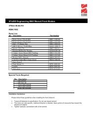
STāSIS Engineering<br />
Signature Series Vehicles<br />
<strong>B8</strong> <strong>A4</strong>/<strong>S4</strong> <strong>Installation</strong> <strong>Guide</strong>lines
Table of Contents<br />
Page<br />
Torque specs 3<br />
Suspension<br />
Front and Rear Suspension, Touring 4<br />
Front and Rear Suspension, Challenge 12<br />
Rear Anti-Roll Bar 25<br />
Differential<br />
Manual Transmission Center<br />
Differential<br />
30<br />
Exhaust 35<br />
Exhaust Kit<br />
Braking<br />
Monobloc Brake Kit 38<br />
Bed-In Procedure 43<br />
Post <strong>Installation</strong> Checklist 44<br />
Page 2 of 44
<strong>B8</strong> <strong>A4</strong>/<strong>S4</strong> TORQUE VALUES<br />
Suspension and Wheels<br />
Front damper to upper mount<br />
37 ft-lbs<br />
Front damper upper mount to body<br />
56 ft-lbs<br />
Front damper fork pinch bolt 30 ft-lbs +<br />
180º<br />
Front damper fork to lower link<br />
66 ft-lbs<br />
Upper link pinch bolt<br />
29 ft-lbs<br />
Rear damper to upper mount<br />
26 ft-lbs<br />
Rear damper upper mount to body<br />
37 ft-lbs<br />
Rear damper to upright<br />
111 ft-lbs<br />
Rear sway bar link to lower control arm<br />
30 ft-lbs<br />
Rear sway bar link to sway bar<br />
30 ft-lbs<br />
Rear sway bar mounts<br />
19 ft-lbs<br />
Wheel spacer bolts<br />
90 ft-lbs<br />
Wheel lug bolts<br />
90 ft-lbs<br />
Brakes<br />
Rotor set screw<br />
48 in-lbs<br />
<strong>STaSIS</strong> Challenge bracket to upright<br />
92 ft-lbs<br />
<strong>STaSIS</strong> Challenge caliper to bracket<br />
70 ft-lbs<br />
Brake line to caliper<br />
14 ft-lbs<br />
Exhaust<br />
Down pipe to mid pipe slip clamp<br />
17 ft-lbs<br />
Hangers to body<br />
17 ft-lbs<br />
Mufflers to mid pipe<br />
17 ft-lbs<br />
Muffler adjustment bracket<br />
17 ft-lbs<br />
Center Diff<br />
Torsen housing to transmission (short bolts) 7 ft-lbs +<br />
90º<br />
Torsen housing to transmission (long bolts)<br />
18 ft-lbs<br />
Tunnel crossmember to transmission mount<br />
15 ft-lbs<br />
Tunnel crossmember to body<br />
41 ft-lbs<br />
Driveshaft to output flange<br />
30 ft-lbs<br />
Drive shaft heat shield<br />
18 ft-lbs<br />
Tansmission drain plug<br />
30 ft-lbs<br />
Page 3 of 44
<strong>A4</strong>/<strong>S4</strong> Suspension, Touring<br />
Touring Suspension Kit<br />
Parts List<br />
Qty Description Part Number<br />
1 Stasis Touring Spring Kit SP04.0005.00<br />
Special Tools Required<br />
Qty Description Part Number<br />
1 Torque Wrench VAG 1331<br />
1 Torque Wrench VAG 1332<br />
1 Engine/transmission jack VAG 1383 A<br />
1 Spring Compressor VAG 1752/1<br />
1 Spring holder VAG 1752/7<br />
1 Rear Spring Compressor VAS 6274<br />
1 Supplementary Set VAS 6274/10<br />
1 Hollow Piston Cylinder VAS 6179<br />
1 Spreader 3424<br />
1 Tensioning strap T10038<br />
Please read ALL instructions prior to attempting installation. Please torque all fasteners to<br />
specifications.<br />
Page 4 of 44
Front Removal and Install<br />
1 Before removing any parts, park the car on a secure, stable, and level surface. Remove wheel trim; pull<br />
trim cap off light-alloy wheels (using puller in vehicle tool kit) and loosen (but do not remove) the wheel lug<br />
nuts. Jack the vehicle up, and place the car on four stable jack stands or use a professional vehicle lift. We<br />
recommend having two people available for certain steps of the installation.<br />
2 Remove wheels<br />
3 Before removing left suspension<br />
strut, remove headlight range<br />
control link from track control link.<br />
(2009 and older)<br />
4 Remove the fastener and plastic<br />
nut on the inside of the fender lip.<br />
This is to provide additional<br />
clearance for the tires. The clip<br />
will not be reinstalled.<br />
5 Remove pinch bolt for upper<br />
control arms. Remove both<br />
joint pins in upper control<br />
arms from wheel bearing<br />
housing. The slits in wheel<br />
bearing housing must not be<br />
widened using a chisel or<br />
similar tool!<br />
Page 5 of 44
6 Disconnect the bolt that connects<br />
the swaybar link to the damper<br />
fork. Bolt can remain on swaybar<br />
link.<br />
7 Remove bolts that connect<br />
damper fork to lower link and<br />
damper. Use spreader (Audi Tool<br />
# 3424 or equivalent) to remove<br />
fork from damper. Pull bearing<br />
housing down to gain enough<br />
clearance to remove fork.<br />
8 Perform these steps on both<br />
sides of the car and then open<br />
the front hood to reach the bolts<br />
that hold the upper mount.<br />
9<br />
Unclip plenum chamber covers-1<br />
& 3 - and remove them.<br />
Page 6 of 44
10 Remove nut - 1 - . Remove filler<br />
neck - 3 - with filler tube from<br />
washer fluid reservoir and body<br />
opening - arrow B - .<br />
11 Remove nuts - arrows - , move<br />
coolant reservoir upward and lay<br />
it aside to access the mounting<br />
bolt.<br />
Do not disconnect any coolant<br />
lines, reservoir does not have to<br />
be removed.<br />
12 Remove bolts - arrows - and<br />
remove suspension strut with the<br />
mounting bracket.<br />
Remove similar bolts from<br />
passenger side and remove<br />
passenger side suspension strut<br />
with the mounting bracket.<br />
13 Remove OEM damper and spring<br />
from upper mount.<br />
Page 7 of 44
14 Remove OEM bumpstop and trim the large<br />
end of the bumpstop to achieve an overall<br />
length of –<br />
2 ¾ inch<br />
**NOTE**<br />
If bump stop length within ¼” of 2 ¾”, no<br />
need to modify<br />
15 Reinstall bumpstop and replace the OEM<br />
spring with the Stasis supplied spring.<br />
*Note*- Bumpstop will no longer capture<br />
on the damper shaft and will sit on the<br />
damper body.<br />
16 Reassemble damper assembly to the<br />
upper mount and reinstall complete<br />
assembly. <strong>Installation</strong> is the reverse of the<br />
removal steps.<br />
*Note*- Bonded rubber suspension<br />
bushings can only be turned to a limited<br />
extent. All mounting bolts of the<br />
suspension links must only be tightened<br />
when the suspension is compressed to the<br />
curb weight position.<br />
Page 8 of 44
Rear Removal and <strong>Installation</strong><br />
1 Remove wheel<br />
2 Remove cover over lower damper bolt, then<br />
remove lower damper bolt (21 mm).<br />
Remove the two fender liner clips one either side<br />
of the damper (#2) by gently prying upwards on<br />
the open end of the clips.<br />
Pushing the fender liner out of the way, remove<br />
upper damper bolts (#1 16 mm) and remove the<br />
damper by dropping straight down through the<br />
opening in the lower control arm.<br />
**<strong>S4</strong> vehicle**<br />
Remove ride sensor lever arm to prevent<br />
damage. Located on rear control arm, driver’s<br />
side.<br />
*Make sure to reconnect during installation*<br />
Page 9 of 44
3 Remove upper mount from damper and set<br />
aside.<br />
4 Remove OEM bumpstop and trim the large end<br />
of the bumpstop to achieve an overall length of –<br />
4 3/8 inch<br />
**Note**<br />
If bump stop length within ¼” of 2 ¾”, no need to<br />
modify<br />
5 Remove rear coil springs with spring compressor<br />
tool VAS 6274 and VAS 6274/10.<br />
Page 10 of 44
6 Install <strong>STaSIS</strong> rear spring with the spring<br />
compressor. Progressive coils towards the top.<br />
7 Install damper assembly and torque to:<br />
Upper bolt: 37 ft-lbs<br />
Lower bolt: 111 ft-lb<br />
Note –<br />
Bonded rubber suspension bushings can only be<br />
turned to a limited extent. The mounting bolts of<br />
the suspension links must only be tightened<br />
when the suspension is compressed to the curb<br />
weight position.<br />
8 Install wheels and tighten. Lower the car onto its wheels and torque all wheel lug bolts to the recommended<br />
torque.<br />
Note: Check wheel alignment after suspension installation<br />
Page 11 of 44
<strong>A4</strong>/<strong>S4</strong> Suspension, Challenge<br />
SL Suspension Kit<br />
Parts List<br />
Qty Description Part Number<br />
2 Front Damper <strong>B8</strong> <strong>A4</strong> SA02.2501.00<br />
2 Rear Damper <strong>B8</strong> <strong>A4</strong> SA02.2511.00<br />
2 Front Springs SP03.1070.00<br />
2 Front Upper Spring Mount SA10.0007.01<br />
2 Rear Springs SP02.6040.00<br />
2 Rear Spring Tenders SP03.0003.00<br />
2 Rear Spring Tender Coupler SP03.0002.00<br />
2 Rear Perch Male SA01.3018.00<br />
2 Rear Perch Female SA01.3019.00<br />
2 UHMWPE Spring Washer SA10.0001.00<br />
2 Rear Spring Perch Spacer SA02.3510.00<br />
2 Perch Wrench SA01.3001.00<br />
2 Front Nylock Nut M12 HA03.0107.00<br />
2 Rear Nylock Nut M10 HA03.0120.00<br />
2 Rear Spacer Bolt M8 HA01.0806.00<br />
2 Rear Spacer Washer M8 HA02.0802.00<br />
Special Tools Required<br />
Qty Description Part Number<br />
1 Torque Wrench VAG 1331<br />
1 Torque Wrench VAG 1332<br />
1 Engine/transmission jack VAG 1383 A<br />
1 Spring Compressor VAG 1752/1<br />
1 Spring holder VAG 1752/7<br />
1 Rear Spring Compressor VAS 6274<br />
1 Supplementary Set VAS 6274/10<br />
1 Hollow Piston Cylinder VAS 6179<br />
1 Spreader 3424<br />
1 Tensioning strap T10038<br />
Please read ALL instructions prior to attempting installation. Please torque all fasteners to<br />
specifications.<br />
Page 12 of 44
Front Removal<br />
1 Before removing any parts, park the car on a secure, stable, and level surface. Remove wheel trim; pull<br />
trim cap off light-alloy wheels (using puller in vehicle tool kit) and loosen (but do not remove) the wheel lug<br />
nuts. Jack the vehicle up, and place the car on four stable jack stands or use a professional vehicle lift. We<br />
recommend having two people available for certain steps of the installation.<br />
2 Remove wheels<br />
3 Before removing left suspension<br />
strut, remove headlight range<br />
control link from track control link.<br />
4 Remove the fastener and plastic<br />
nut on the inside of the fender lip.<br />
This is to provide additional<br />
clearance for the tires. The clip<br />
will not be reinstalled.<br />
5 Remove pinch bolt for upper<br />
control arms. Remove both<br />
joint pins in upper control<br />
arms from the wheel bearing<br />
housing. The slits in the<br />
wheel bearing housing must<br />
not be widened using a chisel<br />
or similar tool! This can<br />
cause the pinch arms to<br />
crack. If the control arm pins<br />
are stuck in the housing, tap<br />
lightly with a rubber mallet on<br />
the bottom of the control<br />
arms.<br />
Page 13 of 44
6 Disconnect the bolt that connects<br />
the swaybar link to the damper<br />
fork. Bolt can remain on swaybar<br />
link.<br />
7 Remove bolts that connect<br />
damper fork to lower link and<br />
damper. Use spreader (Audi Tool<br />
# 3424 or equivalent) to remove<br />
fork from damper. Pull bearing<br />
housing down to gain enough<br />
clearance to remove fork.<br />
8 Perform these steps on both<br />
sides of the car and then open<br />
the front hood to reach the bolts<br />
that hold the upper mount.<br />
9<br />
Unclip plenum chamber covers-1<br />
& 3 - and remove them.<br />
Page 14 of 44
10 Remove nut - 1 - . Remove filler<br />
neck - 3 - with filler tube from<br />
washer fluid reservoir and body<br />
opening - arrow B - .<br />
11 Remove nuts - arrows - , move<br />
coolant reservoir upward and lay<br />
it aside to access the mounting<br />
bolt.<br />
Do not disconnect any coolant<br />
lines, reservoir does not have to<br />
be removed.<br />
12 Remove bolts - arrows - and<br />
remove suspension strut with the<br />
mounting bracket.<br />
13 Remove OEM damper and spring<br />
from upper mount.<br />
Note: You will not reuse the OEM<br />
bumpstop, the thick washer, and<br />
the nylock nut that sits on top of<br />
the damper shaft.<br />
Page 15 of 44
14 Remove swaged aluminum upper<br />
spring seat retainer. Use a small<br />
chisel and hammer to bend over<br />
the swaged lip. A die grinder can<br />
also be used to grind the lip off of<br />
the center of the aluminum<br />
retainer.<br />
15 Install spring with delrin upper<br />
mount onto the <strong>STaSIS</strong> damper.<br />
Install upper cradle and rubber<br />
upper mount onto the damper<br />
assembly. Hold upper damper<br />
pin in between the cradle and<br />
mount with a wrench while<br />
tightening the nut for the damper<br />
pin to the rubber upper mount.<br />
Tighten nylock nut to 37 ft-lbs.<br />
CAUTION – DO NOT grab the<br />
damper shaft with any tools while<br />
tightening the nylock nut.<br />
NOTE – Spring assembly will be<br />
loose at preset perch height. This<br />
is normal and will get loaded once<br />
installed in the vehicle.<br />
Page 16 of 44
16 <strong>Installation</strong> is the reverse of<br />
removal.<br />
Once the damper is installed<br />
check that the spring perch is set<br />
at the proper installed height, as<br />
shown in the picture. The<br />
Dimension should be 76mm from<br />
the top of the cylinder head<br />
(yellow mark) to the bottom of the<br />
locking coil ring.<br />
Before compressing the<br />
suspension, confirm that the<br />
upper urethane spring mounts are<br />
properly seated on the springs,<br />
the springs will self center onto<br />
the cradle once the suspension is<br />
compressed.<br />
Note: Bonded rubber suspension<br />
bushings can only be turned to a<br />
limited extent. All mounting bolts<br />
of the suspension links must only<br />
be tightened when the<br />
suspension is compressed to the<br />
curb weight position. This can be<br />
done by jacking up the wheel<br />
while the car is on the lift.<br />
17 Install Wheel and tighten<br />
Note – do not fully tighten bolts<br />
until car is at ride height.<br />
Page 17 of 44
Rear Removal<br />
1 Remove wheel<br />
2 Remove upper damper bolts. Then<br />
remove lower damper bolt and<br />
remove damper.<br />
Note: Discard the lower bolt cover.<br />
It will not be reused.<br />
*<strong>S4</strong> Vehicle*<br />
Remove ride sensor lever arm to<br />
prevent damage. Located on rear<br />
control arm, driver’s side.<br />
*Make sure to reconnect during<br />
installation*<br />
Page 18 of 44
3 Remove upper mount from OEM<br />
damper and set aside.<br />
Note: It will be reused when<br />
installing the <strong>STaSIS</strong> damper.<br />
4 Insert pry bar between upright and<br />
lower control arm (see picture) and<br />
push down to relieve tension from<br />
spring. You may need assistance to<br />
remove the spring while you are<br />
pushing the suspension down.<br />
5 Remove the OEM lower rubber<br />
spring mount, it will not be reused.<br />
Note: You may remove the stone<br />
guard to make it easier to make<br />
height adjustment, however this is<br />
not a requirement.<br />
Page 19 of 44
Rear <strong>Installation</strong><br />
6 Install <strong>STaSIS</strong> lower spring perch<br />
onto lower control arm and secure<br />
with the supplied bolt.<br />
Note: Check that the perch is set<br />
to the proper installed height. As<br />
shown in the picture below.<br />
The dimension should be 64mm<br />
from the bottom of the rear spring<br />
perch spacer to the spring seat<br />
(yellow mark). DO NOT include<br />
the UHMWPE washer thickness<br />
in the measurement.<br />
Page 20 of 44
7 Install <strong>STaSIS</strong> spring and OEM<br />
upper rubber mount. Earlier kits<br />
include a tender spring with a<br />
coupler on top of the main spring.<br />
Note: You will have to use a pry<br />
bar in the same manner used to<br />
remove the OEM spring<br />
8 Install the OEM upper damper<br />
mount onto the <strong>STaSIS</strong> damper.<br />
Grab cylinder head with a wrench<br />
and tighten nylock nut to 37 ft-lbs.<br />
9 Install damper assembly and<br />
torque to:<br />
Upper bolt: 37 ft-lbs<br />
Lower bolt: 111 ft-lb, longer bolt<br />
spacer goes against the upright,<br />
short spacer between the bolt<br />
head and damper end eye.<br />
Note –<br />
Bonded rubber suspension<br />
bushings can only be turned to a<br />
limited extent. The mounting<br />
bolts of the suspension links must<br />
only be tightened when the<br />
suspension is compressed to the<br />
curb weight position. This can be<br />
done by jacking up the wheel<br />
while the car is on the lift.<br />
Page 21 of 44
10 Install wheels and tighten. Lower the car onto its wheels and torque all wheel lug bolts to the<br />
recommended torque.<br />
Check ride height – See next page<br />
<strong>STaSIS</strong> recommended ride heights-<br />
Front - 13 1/2” from the center of the wheel to the fender lip<br />
Rear - 13 3/8” from the center of the wheel to the fender lip<br />
Note: Check wheel alignment after suspension installation<br />
Rev. 1 11/2/08<br />
Page 22 of 44
<strong>STaSIS</strong> Signature Line Ride Height Adjustment<br />
Ride height inspection and adjustment procedure:<br />
1. After completing installation of the kit, set the vehicle on the ground and drive the car around the block<br />
to settle the suspension. To take ride height measurements MAKE SURE THE VEHICLE IS PARKED<br />
ON A LEVEL SURFACE. VERY IMPORTANT!<br />
2. Measure the ride height of the vehicle at four points for future reference. Measure from the center of the<br />
wheels to the bottom of the fender lip.<br />
3. If you are pleased with this ride height then you are done, save the measurements for future reference.<br />
If not continue to step 4.<br />
4. Calculate the difference between the actual ride height and the ride height you would like the car to sit<br />
at for the right front wheel. For optimum handling we recommend this be done with the driver in the car<br />
and ¾ of a tank of fuel. We recommend that the distance between the center of the wheels and the<br />
bottom of the fender lip is not set below 13.0 inches. The suspension is operating too close to its<br />
maximum bump travel and handling can be negatively impacted.<br />
5. The ratio between the front shock body motion and wheel motion is about 0.65 to 1 and the rear is 0.80<br />
to 1. This means that the wheel travels about 1 inch for every 0.65 inches of shock body travel on the<br />
front and 0.80 inches of spring travel on the rear. Therefore, for example, if you wanted to lower the car<br />
½ inch from its current ride height at the right front wheel, then you would have to lower the lower spring<br />
perch on the right front shock body by ½ x 0.65 = 0.32 inches. The rear motion ratio is calculated the<br />
same way.<br />
6. Repeat steps 4 & 5 for the left front, left rear and right rear wheels.<br />
7. Armed with the data from steps 4,5 & 6, securely jack the car up and place it on four jack stands.<br />
Remove the wheels if necessary to reach the lower spring perches. For the front dampers, loosen the<br />
lower perch lock ring and thread the lower perch up or down by the amount you have calculated in step<br />
5. The rear spring perch does not have a locking ring and can be turned freely. Record the location of<br />
the perches so you can have it as a future reference if needed. Once the desired height is attained,<br />
tighten the locking perch against the spring perch.<br />
8. Place the wheels back on the car and lower it to the ground. Drive the car around the block or press up<br />
and down on the car 3 or 4 times at each of the four wheels to settle the suspension before you make<br />
any measurements. Make sure the car is in the exact same location as before and go to step 2.<br />
Page 23 of 44
<strong>STaSIS</strong> Signature Line Maintenance Instructions<br />
Custom Valved Ohlins Threaded Steel Dampers<br />
The STASIS Coil Over kit is designed to provide superior service for the lifetime of your vehicle. As this<br />
suspension system is a race car derived kit with high performance components, routine maintenance is required<br />
to insure the optimal operation of your suspension system.<br />
We recommend the following steps are performed bi-annually, preferably before and after the winter season.<br />
Vehicles that are exposed to more abusive environments, such as sea salt, road salt or dirt roads may<br />
necessitate more frequent maintenance.<br />
1. Securely support the vehicle on four jack stands and remove the road wheels.<br />
2. Clean the threaded portion of the damper with a non metallic brush using soap and water.<br />
3. We recommend lowering or raising the lower spring perch to allow access to clean the<br />
threaded portion of the damper that is covered by the perches.<br />
4. Lubricate the threaded portion of the damper with “Boeshield T9” lubricant-protectant or a<br />
similar wax based lubricant.<br />
5. Return the perches to their original location and tighten the locking perches. Spray<br />
protectant on the remaining components of the damper assembly.<br />
6. Check the rear spherical bearings and verify that they are properly lubricated.<br />
7. Service your dampers with <strong>STaSIS</strong> every 2 years to maintain product warranty and optimal<br />
functionality.<br />
8. If you have any questions about this, please call <strong>STaSIS</strong> at 707-935-9700.<br />
Secure the road wheels and return the vehicle to the ground. Watch that the springs seat properly on the spring<br />
perches<br />
Page 24 of 44
<strong>A4</strong>/<strong>S4</strong> Suspension<br />
*When performing complete Sig.Series package, removing OEM exhaust prior to ARB<br />
highly recommended*<br />
Rear Anti-Roll Bar<br />
Applications List<br />
Qty Description Part Number<br />
1 <strong>A4</strong> <strong>B8</strong> <strong>STaSIS</strong> Rear ARB 24 mm SA15.2100.00<br />
1 <strong>S4</strong> <strong>B8</strong> <strong>STaSIS</strong> Rear ARB 28mm SA15.3100.00<br />
Tools Required<br />
Description<br />
13mm Socket<br />
10mm Triple Square Socket<br />
16mm Socket<br />
16mm Box End Wrench<br />
Medium Prybar<br />
Torque Values<br />
ARB Mounting Bracket Bolts, 10mm Triple Square<br />
Lower Drop Link Bolts<br />
Upper Drop Link Bolts<br />
Chassis Cross Brace Bolts<br />
Exhaust Muffler Hanger Nuts<br />
29 N m<br />
54 N m<br />
54 N m<br />
54 N m<br />
20 N m<br />
Page 25 of 44
1 Before removing any parts, jack the vehicle up, and place the vehicle on four stable jack stands or use<br />
a professional vehicle lift.<br />
2 Support the exhaust and remove the two<br />
exhaust muffler hanger nuts (one per<br />
side), 13mm socket.<br />
3 Gently pry the two center exhaust rubber<br />
hangers of off the exhaust. Use a<br />
lubricant (i.e. WD-40) if required.<br />
Page 26 of 44
4 Remove the center chassis cross brace,<br />
16mm socket.<br />
5 Lower exhaust to give clearance for<br />
removal and installation of the ARB.<br />
6 Loosen but do not remove the lower ARB<br />
drop link bolts, 16mm socket.<br />
Page 27 of 44
7 Disconnect upper ARB drop link bolts<br />
from the ARB and rotate link to the side,<br />
16mm end wrenches<br />
8 Remove the bolts attaching the ARB<br />
brackets to the subframe (both sides),<br />
10mm Triple Square Socket.<br />
9 Remove the stock ARB from the car.<br />
Gently pry off the ARB mount brackets<br />
and rubber bushings (these will be reused<br />
with the <strong>STaSIS</strong> ARB).<br />
OEM ARB bushings have enough flex to<br />
accommodate the <strong>STaSIS</strong> ARB.<br />
Page 28 of 44
10 Install the OEM bushings and mounting<br />
brackets with a centered distance of 26<br />
¾” between the bolt centers of each<br />
clamp.<br />
11 Install <strong>STaSIS</strong> ARB into vehicle. It may be<br />
necessary to deflect the upper control arm<br />
by gently using a pry bar as shown to<br />
facilitate the installation.<br />
12 Once located, installation is the reverse of<br />
all removal steps. Make sure to locate<br />
drop link bolts into the ARB before<br />
tightening the ARB Mounting Bracket<br />
bolts. Torque all fasteners to the<br />
specifications shown.<br />
*NOTE*: After mounting to the vehicle,<br />
make sure your ARB is centered between<br />
the two clamps to avoid possible binding<br />
and interference with suspension<br />
components during vehicle operation.<br />
Page 29 of 44
<strong>A4</strong>/<strong>S4</strong> Center Differential <strong>Installation</strong><br />
Parts List:<br />
Qty Description Part Number<br />
1 High Bias Torsen DL01.0012.00<br />
Special Tools Required<br />
Removal<br />
Qty Description Part Number<br />
1 Drip Tray VAG 1306<br />
1 Torque Wrench VAG 1331<br />
1 Loosen quick-release fasteners - 2 and 3 - and<br />
remove rear noise insulation.<br />
2 Disconnect exhaust system at clamps – arrows<br />
Disengage rear section of exhaust system at rubber<br />
mounting and remove<br />
Page 30 of 44
3 If installed, remove heat shield for drive shaft - arrows<br />
4 Remove bolts – arrows – at transmission/drive shaft<br />
flange.<br />
Slide drive shaft together toward rear final drive. The<br />
constant velocity joints can be moved axially.<br />
5 Secure drive shaft to selector rod. Place drip tray VAG<br />
G1306 under transmission.<br />
Support transmission using engine/transmission jack<br />
V.A.G 1383 A with transmission support T10337<br />
attached.<br />
6 Remove tunnel crossmember bolts - arrows -<br />
Page 31 of 44
7 Carefully lower the transmission using<br />
engine/transmission jack V.A.G 1383 A .<br />
Do not lower more then, 100 mm maximum.<br />
Remove nuts - arrow - and tunnel crossmember.<br />
8 Place used oil collection and extraction device V.A.G<br />
1782 under transmission.<br />
Remove bolt - arrow - and drain transmission oil.<br />
Install bolt - arrow - and tighten it to 40 Nm.<br />
9 Remove bolts - A - and - arrows - and remove center<br />
differential housing - B - carefully.<br />
10 If gear carrier - 1 - remains in center differential housing,<br />
proceed as follows:<br />
Grip side ridge on gear carrier - 1 - using a pair of pliers<br />
and remove it in direction of - arrow A - .<br />
Using a rubber hammer , tap housing on alternating<br />
sides - B arrows - .<br />
CAUTION!<br />
Do not damage sealing surfaces when doing so.<br />
Remove center differential.<br />
Page 32 of 44
<strong>Installation</strong><br />
11 Install gear carrier on transmission as follows:<br />
<strong>Installation</strong> position: The tab on gear carrier - arrow A -<br />
must be in opening in transmission housing - arrow B - .<br />
12 Clean both joint surfaces in the housing.<br />
Position center differential - 2 - over gear carrier - 1 - .<br />
Insert plate spring - 5 - , adjustment shim(s) - 4 - and<br />
spring - 3 - in center differential housing - 6 - .<br />
Plate spring installation location - 5 - : The camber on<br />
inner diameter - arrow - faces toward center differential<br />
housing - 6 - .<br />
Apply sealing paste AMV 188 001 02 evenly and not too<br />
thick.<br />
Then position center differential housing - 6 - on<br />
transmission.<br />
13 Press center differential housing - B - on until it makes<br />
contact with transmission housing and hold it securely.<br />
Install and tighten new bolts - arrows - . Tightening<br />
specification: 7 ft-lbs plus an additional 90 degree turn.<br />
Tighten bolts - A - Tightening specification: 18 ft-lbs.<br />
Page 33 of 44
14 Tighten tunnel crossmember on transmission mount -<br />
arrows - . Tightening specification: 15 ft-lbs.<br />
15 Raise transmission and tighten the tunnel crossmember<br />
bolts - arrows - . Tightening specification: 41 ft-lbs.<br />
Tighten drive shaft on the transmission.<br />
Tightening specification: 30 ft-lbs<br />
Top off transmission oil and check oil level.<br />
Install exhaust system and align it without tension.<br />
16 Install drive shaft heat shield.<br />
Tightening specification: 18 ft-lbs.<br />
17 Reinstall rear section of exhaust system.<br />
Page 34 of 44
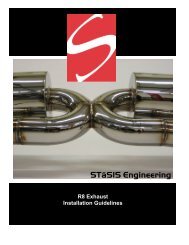
<strong>A4</strong>/<strong>S4</strong> Exhaust<br />
Exhaust Kit <strong>Installation</strong><br />
Applications<br />
Qty Description Part Number<br />
1 <strong>A4</strong> Sig Series Twin Tip Exhaust EX05.<strong>A4</strong><strong>B8</strong>.00<br />
1 <strong>S4</strong> Sig Series Quad Tip Exhaust, Low SE221-E10-01-00<br />
1 <strong>S4</strong> Sig Series Quad Tip Exhaust, High SE221-E10-02-00<br />
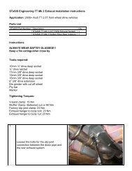
Instructions<br />
1 Place vehicle in secure position. Remove factory<br />
exhaust system up to the catalytic converter<br />
assembly. Leave rubber hangers in position.<br />
2 Using a 10mm socket, remove the 3 plastic nuts<br />
holding the right side cavity cover.<br />
*<strong>S4</strong> Vehicle*<br />
Steps 2-6 do not apply<br />
3 Remove the push clip retainer in the rear right<br />
corner of the cavity cover. Remove the cover from<br />
the vehicle.<br />
Page 35 of 44
4 Gently pull to remove the stock rear valence.<br />
5 Install the supplied exhaust hanger onto the right<br />
side muffler.<br />
6 Install the supplied heat shield for the right side of<br />
the vehicle using the speed nuts pictured above.<br />
Page 36 of 44
7 Make sure there is adequate clearance between the<br />
heat shield and the sway bar. The heat shield<br />
should be tight against the chassis. If not, gently<br />
bend the heat shield.<br />
Attach new valence by gently pressing on tabs<br />
across the bumper.<br />
Attention: S-line vehicles must trim the new<br />
valence to the provided template to avoid<br />
interference during operation.<br />
8 Install mid pipe and driver’s side muffler into<br />
position. Slipping it into the mid-pipe and secure<br />
loose enough for adjustment<br />
9 Remove hardware from adjustment bracket. Be<br />
sure to keep them for reinstallation.<br />
10 Install passenger side into position. Slipping it into<br />
the mid-pipe and secure loose enough for<br />
adjustment.<br />
11 Reinstall hardware for adjustable bracket and<br />
tighten flanges and bracket with mufflers aligned<br />
and spaced evenly.<br />
Confirm the side-side distances are equal (x).<br />
Loosen nut (arrow) on adjustable bracket and align<br />
muffler as necessary. Torque nut to 23 Nm (17 ftlb)<br />
12 Loosen factory hangers at rear of muffler with 13mm<br />
wrench. Using the slots in these hangers and the<br />
adjustable bracket, position tips in centers of<br />
bumper cutouts.<br />
13 Test drive and check for rattles. Re-adjust as<br />
necessary to provide proper clearance.<br />
Page 37 of 44
<strong>A4</strong>/<strong>S4</strong> Brakes<br />
Optional <strong>STaSIS</strong> Monobloc Brake Kit<br />
Parts List:<br />
Qty Description Part Number<br />
1 Rotor Alcon 370X32 RH BR01.1006.00<br />
1 Rotor Alcon 370X32 LH BR01.1007.00<br />
4 SHCS M12x1.750x60 12.9 Blue HA01.1206.75<br />
1 Caliper Alcon Mono6 RH Trailing BR03.1002.00<br />
1 Caliper Alcon Mono6 LH Trailing BR03.1003.00<br />
2 Bracket <strong>B8</strong> 14.5 Mono6 BR04.1400.00<br />
1 Line Kit Audi Front Alcon BR20.1007.00<br />
2 Brake Line Stop Washer BR20.1008.00<br />
1 Project Mµ NS Pad Set BP01.6001.00<br />
1 Fluid Motul 5.1 BP99.1000.00<br />
<strong>Installation</strong> <strong>Guide</strong>lines<br />
Please follow these guidelines when installing the front brake kit.<br />
• Torque all fasteners to specification. Do not use an impact wrench.<br />
• The rotors are side-specific, rotational direction is labeled. Open portion of crescents face toward the<br />
direction of rotation.<br />
• The rotors have been dynamically balanced by machining the outer edge. Flat spots along the outer<br />
diameter are normal and will not affect the performance of the rotor.<br />
• Tighten hydraulic connections with a line wrench.<br />
• Bleed brakes properly to assure proper brake operation; the use of a power bleeder is<br />
recommended.<br />
• Ensure all ABS sensor and Pad wear sensor plugs are reconnected.<br />
• Proper pad bedding is essential to proper brake operation.<br />
• Initially drive the car with low braking force to check brake operation; then follow all steps listed in the<br />
bedding process outlined at the end of this instruction manual.<br />
• During bedding do not thermally shock the rotors with aggressive braking before the rotors have come<br />
up to temperature. Cracks on new rotors can form due to thermal shock. Gradually increase brake<br />
pressures as instructed in the bedding procedure.<br />
• After bedding brakes re-torque wheel nuts to proper torque specifications.<br />
• If vibration occurs during normal usage, check for abnormal pad wear deposits on the rotor. Double<br />
check all fasteners and repeat the bedding process 2-3 cycles until the pad deposits on the rotor<br />
becomes uniform.<br />
• If the vehicle is driven in adverse weather conditions, <strong>STaSIS</strong> Engineering recommends annual<br />
cleaning and inspection of the rotor crescents. A common source of vibration can be attributed to dirt<br />
completely filling in the crescents on the inboard side of the rotors which in turn will not allow the pad to<br />
function properly.<br />
• Brake rotor wall thickness wear limit is 1.0 mm per side of rotor. Rotor face runout limit +/- 0.010 in,<br />
when taking measurement make sure rotor is tightened down to the hub at all 5 bolt locations.<br />
Page 38 of 44
Instructions<br />
1 Sort the parts in the brake kit for the right and left side.<br />
Brake bleeders face upward. Caliper mounting brackets<br />
are universal.<br />
Install brake pads in calipers.<br />
Install brake lines with banjo bolt and crush washers.<br />
Orient brake line facing straight up as shown.<br />
2 Raise vehicle and remove the front wheels.<br />
3 Using brake cleaner, clean the brake line connection at<br />
the body flange. Remove all dirt and debris from this<br />
area and from the line connection threads so that no dirt<br />
will get into the new brake line when it is installed.<br />
4 Remove the caliper.<br />
Remove the ABS sensor wire from the holding bracket<br />
on the brake caliper to facilitate removing the caliper.<br />
Disconnect the brake pad wear sensor wire from the<br />
driver’s side front brake inner pad.<br />
Remove caliper mounting bolts (the bolts holding the<br />
caliper mounting bracket to the upright). Save these<br />
bolts as they will be reused.<br />
Remove caliper and support it so that the brake line is<br />
not under tension.<br />
5 Remove the brake rotor. Clean the hub, removing all<br />
rust from the rotor mounting surface, the rotor pilot and<br />
wheel pilot. Apply some anti-seize to the pilot surface to<br />
prevent rotors and wheels from sticking in the future.<br />
Do not get any anti-seize on the rotor mounting surface<br />
of the hub.<br />
Page 39 of 44
6 Install caliper mounting brackets using the stock<br />
mounting bolts and torque to 92 ft-lb. The bracket will<br />
mount to the outside face of the upright with the angle<br />
flange going over the mounting ears in the upright. The<br />
OEM bolts will fit through the upright from the backside<br />
and thread into the bracket.<br />
7 Install the new rotors making sure they are free of dirt<br />
and grease. Tighten the rotor retaining bolt to 48 in-lbs.<br />
8 Place the caliper with the brake pads installed onto the<br />
caliper mounting bracket and install the caliper mounting<br />
bolts M12 x 1.75 x 60 and torque to 70 ft-lb. If the caliper<br />
will not go over the rotor because the pads are too close<br />
together, push the pads back using a pad spreader.<br />
Note: When rotating, the rotor must always pass the<br />
small caliper piston first. Therefore in a trailing caliper<br />
application like we have here the small caliper piston will<br />
be at the bottom of the caliper. The purpose is to insure<br />
even pad wear.<br />
Page 40 of 44
9<br />
Replace the front brake lines.<br />
Use an 11-mm line wrench on the hard line<br />
nut and a 16-mm wrench on the flats on the<br />
flex line hose-end.<br />
Remove the stock flexible line from the hard<br />
line and completely remove the stock caliper<br />
and line from the vehicle.<br />
Install the copper washer onto the new line<br />
as shown.<br />
Install the new flexible line, with washer using<br />
the stock spring clip under the hard line nut<br />
and clean with brake clean once tightened.<br />
Install the rubber brake line grommet into the<br />
factory bracket on the back of the upright.<br />
Re-connect all ABS sensor wires and the<br />
brake pad wear sensor.<br />
10 Make sure that the brake rotor spins freely<br />
and that the rotor is flush on the hub.<br />
11 Bleed the brakes using fresh high-quality<br />
brake fluid. A power bleeder is highly<br />
recommended. Two bleeders are on each<br />
front caliper.<br />
Bleed the outers first until no air exits, then<br />
the inners until no air exits<br />
Wait 10-15 minutes.<br />
Power bleed again while turning the ignition<br />
on/engine off and stroke the brake pedal five<br />
times when each bleeder is open. This<br />
process will assure a proper bleed with the<br />
ABS equipped system.<br />
Tighten all bleeders securely.<br />
12 Clean all brake line connections with brake<br />
cleaner and compressed air so that they are<br />
clean and dry. Start engine and pressurize<br />
brake system several times and check for<br />
leaks at all the brake line connections.<br />
Correct any leaks before driving the car.<br />
13 Check the clearance between the wheels and<br />
the new brake calipers. Make sure that there<br />
is at least 1/8”(0.125”) between the wheel<br />
and the caliper.<br />
Page 41 of 44
14 Verify that all bolts are tight and torque the<br />
wheel lug bolts.<br />
15 Test drive the car using the brakes gently.<br />
16 WARNING: Do not aggressively test the<br />
brakes until they are properly bedded.<br />
17 Bed the pads and rotors. See the Bedding<br />
Procedure attached to these installation<br />
instructions. After brakes are fully bedded<br />
recheck wheel lug bolt torque.<br />
Page 42 of 44
<strong>STaSIS</strong> Bedding Procedure<br />
After installing new pads, rotors, or both, it is necessary to properly bed the pad to the rotor<br />
before using the brakes to their full capacity.<br />
What is bedding?<br />
Bedding is the process of depositing a layer of pad material (often called the transfer layer or<br />
transfer film) onto the surface of the rotor. Brake rotors used on OEM style brake systems do<br />
not require this transfer layer as the braking system is relying on friction between the pad and<br />
the rotor material to slow the vehicle down. On <strong>STaSIS</strong> rotors, the bond between the pad<br />
and the transfer layer is much stronger and the frictional characteristics of the pad/transfer<br />
layer interface are far better than those of a pad/rotor interface. It is therefore crucial to bed<br />
pads properly to ensure the reliability, performance, and longevity of your <strong>STaSIS</strong>/ALCON<br />
brake system.<br />
When should I bed pads and rotors?<br />
Bedding is recommended whenever you install new pads or rotors, or experience vibrations<br />
while braking.<br />
• For new pads and rotors, bedding allows the manufacturing resins in the pads to burn off<br />
slowly to avoid uneven deposits or pad glazing. Bedding also allows the rotors to relieve<br />
any thermal stresses incurred during the manufacturing process.<br />
• Vibrations felt through the brake pedal are most commonly a result of uneven pad<br />
deposition, which is remedied by re-bedding the existing components.<br />
Bedding Process<br />
1. Upon initial installation do not bed the rotors immediately. Drive the vehicle with normal to<br />
light braking for 1-2 days to allow the pad and rotor surfaces to conform better before bedding<br />
in at higher temperatures.<br />
2. Find a suitable road. You will need a relatively straight road with minimal traffic where you<br />
can safely (and legally!) reach speeds up to 65 MPH.<br />
3. Once the car has been driven with light braking for a few miles to bring the rotors up to the<br />
proper operating temperature, bring the car up to approximately 65 MPH. Gently apply<br />
constant pressure (about 10%) to the brakes, bringing the car down to about 20 MPH.<br />
4. Accelerate briskly back to 65 MPH. Apply the brakes again, however this time use more<br />
force (about 20%).<br />
5. Repeat steps 2 and 3, each successive time applying more pressure. Your last two brake<br />
applications should engage or nearly engage the ABS system.<br />
6. Do not immediately stop the vehicle with your foot on the brakes after step 5, the<br />
concentrated heat from the pad sitting on a non-rotating rotor will warp the rotor. Drive<br />
vehicle using absolutely minimal brake application to cool the rotors to ambient temperature<br />
(freeway driving).<br />
7. Once the system has cooled, repeat the entire process.<br />
After completing two heat cycles on the rotors, check the rotors for an even, slightly hazy<br />
coating (often with a slight blue tint). Any spotting or blotches indicate uneven pad<br />
deposition. Repeat the process until the rotor surface is even.<br />
Page 43 of 44
<strong>A4</strong>/<strong>S4</strong> Signature Series Post <strong>Installation</strong> Checklist<br />
Suspension<br />
o<br />
o<br />
o<br />
o<br />
o<br />
o<br />
Fastener clip removed from the inside fender lip on the front right and left sides.<br />
Ensure nylock nuts are completely tightened on the front and rear upper adapter<br />
pins. Loose nuts will cause clunking noises from the damper.<br />
Ensure both front swaybar link bolts are reconnected to the damper fork.<br />
Check orientation of the rear bushing spacers- shorter one against the bolt head.<br />
Ensure all suspension and anti-roll bar mounting bolts were tightened with the<br />
suspension compressed to the curb weight position.<br />
Check ride height and alignment after driving the car for a few miles, as the<br />
rubber bushings will cause the car to settle.<br />
Brakes<br />
o<br />
o<br />
o<br />
o<br />
o<br />
o<br />
o<br />
o<br />
Ensure all ABS sensor and Pad wear sensor plugs are reconnected<br />
Ensure brake line grommet is properly seated on bracket. Cycle steering from full<br />
lock left to full lock right (with the suspension compressed to the curb weight<br />
position) and inspect for possible binding on the brake line.<br />
After bleeding brakes, cycle pressure to the pedal and double check all bleed screws<br />
and brake line connections for possible leakage.<br />
Drive the car at low speeds for a few miles to check brake operation before<br />
beginning brake bedding procedure.<br />
During bedding do not thermally shock the rotors with aggressive braking before the<br />
rotors have come up to temperature. Cracks on new rotors can form due to thermal<br />
shock. Gradually increase brake pressures as instructed in the bedding procedure.<br />
After bedding brakes re-torque wheel nuts to proper torque specifications.<br />
After installation and bleeding is completed double check brake fluid level.<br />
If vibration occurs during normal usage, check for abnormal pad wear deposits on<br />
the rotor. Double check all fasteners and repeat the bedding process 2-3 cycles until<br />
the pad deposits on the rotor becomes uniform.<br />
Exhaust<br />
o<br />
o<br />
o<br />
o<br />
During and after install, wipe off all assembly and shipping particles from the<br />
exhaust. If dust is not wiped off, once the exhaust gets hot, the particles burn onto<br />
the stainless steel finish and become permanent.<br />
For S-line vehicles, ensure corners of the new valence are trimmed to the included<br />
template. The exhaust will fit without trimming, but once the exhaust gets hot, it<br />
will extend into and melt the valence.<br />
Ensure the exhaust tips on both sides protrude from the bumper evenly and are not<br />
touching any body panels. Clearance to all body panels should account for thermal<br />
expansion of the exhaust, up to ½ inch in length.<br />
Apply anti seize to all assembly bolts to allow for ease of removal.<br />
Page 44 of 44