

LaserGas II SP & SP Compact - Webshop, Gas Analysis Technology
LaserGas II SP & SP Compact - Webshop, Gas Analysis Technology
LaserGas II SP & SP Compact - Webshop, Gas Analysis Technology

You also want an ePaper? Increase the reach of your titles
YUMPU automatically turns print PDFs into web optimized ePapers that Google loves.
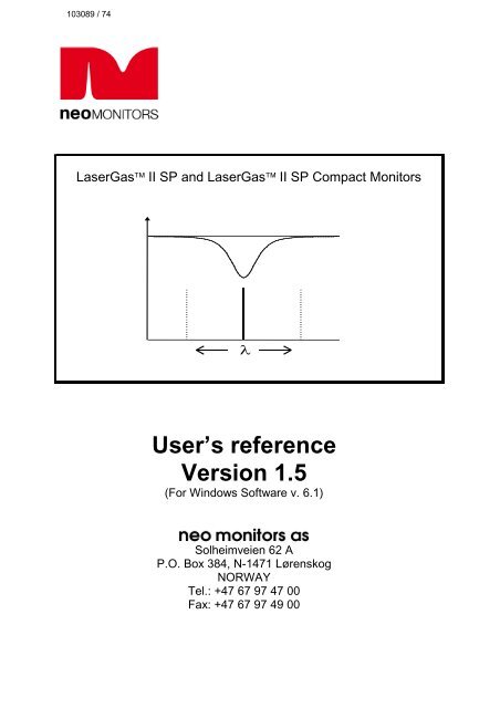
<strong>Laser<strong>Gas</strong></strong> <strong>II</strong> <strong>SP</strong> and <strong>Laser<strong>Gas</strong></strong> <strong>II</strong> <strong>SP</strong> <strong>Compact</strong> Monitors<br />
λ<br />
User’s reference<br />
Version 1.5<br />
(For Windows Software v. 6.1)<br />
Solheimveien 62 A<br />
P.O. Box 384, N-1471 Lørenskog<br />
NORWAY<br />
Tel.: +47 67 97 47 00<br />
Fax: +47 67 97 49 00
<strong>Laser<strong>Gas</strong></strong> <strong>II</strong> <strong>SP</strong>/<strong>SP</strong> <strong>Compact</strong> Monitor,<br />
User’s Reference v.1.5<br />
PRODUCT DATA<br />
Manufacturer<br />
Country of origin<br />
Model<br />
NEO Monitors AS<br />
Norway<br />
<strong>Laser<strong>Gas</strong></strong> <strong>II</strong><br />
Environmental conditions<br />
Operating temperature<br />
Storage temperature<br />
Protection classification<br />
Ratings<br />
Input power supply unit<br />
Output power supply unit<br />
Input transmitter unit<br />
-20 o C to +55 o C<br />
-20 o C to +55 o C<br />
IP66<br />
100 – 240 VAC, 50/60 Hz, 0.36 – 0.26 A<br />
24 VDC, 900 – 1000 mA<br />
18 – 36 VDC, max. 20 W<br />
4 - 20 mA output 500 Ohm max. isolated<br />
Relay output<br />
1 A at 30 V DC<br />
Laser Class Class 1 acc. to IEC 60825-1<br />
I
<strong>Laser<strong>Gas</strong></strong> <strong>II</strong> <strong>SP</strong>/<strong>SP</strong> <strong>Compact</strong> Monitor, User’s<br />
Reference v.1.5<br />
QUICK REFERENCE LIST, INSTALLATION OF LASERGAS <strong>II</strong> MONITORS<br />
Ref<br />
no.<br />
Description<br />
Users manual ref.<br />
1 Mount transmitter purging unit to flange 3.1.1, Figure 3-1<br />
2 Mount receiver purging unit to flange 3.1.1, Figure 3-1<br />
3 Use laser alignment jig and align transmitter purging unit 3.4.1<br />
4 Use laser alignment jig and align receiver purging unit 3.4.2<br />
5 Install purging gas (pressurised air/nitrogen) on both purging units 3.1.2<br />
6 Mount the window adapter ring to the purging unit (both sides) 3.1.1, Figure 3-1<br />
7 Open purging 3.1.2<br />
8 Mount transmitter unit to purging unit (Remember O-ring) 3.1.1<br />
9 Mount receiver unit to purging unit (Remember O-ring) 3.1.1<br />
10 Connect transmitter and receiver units with the correct cable. 3.1.1<br />
6.2<br />
11 Connect optional output signals (4-20mA, warning relays, etc.) to<br />
the “Auxiliary” plug.<br />
3.1.1<br />
6.4<br />
12 Connect Ethernet cable to the “Network” connector (optional). 6.1, Figure 6-1<br />
13 If external 4-20 mA temperature and/or pressure sensors are<br />
used, connect the input signals to the power supply unit or the<br />
main power connector.<br />
6.3<br />
6.6<br />
14 Connect the power supply unit to the transmitter 3.1.1, 6.3<br />
15 Switch the monitor on by applying 220/110VAC to the power 3.1.1<br />
supply (alternatively apply 24 V DC directly to the transmitter unit)<br />
16 Observe start up sequence on display on transmitter unit 3.2.1<br />
17 Connect a voltmeter using the supplied cable with miniature power<br />
plug to the alignment jack on the transmitter unit and measure DC<br />
signal<br />
3.5<br />
18 Fine adjust alignment of transmitter purging unit for maximum 3.5<br />
transmission (max signal)<br />
19 Fine adjust alignment of receiver purging unit for maximum 3.5<br />
transmission (max signal)<br />
20 Observe transmission on display. For a low dust process gas the<br />
transmission should be between 90 to 100 %<br />
21 Set-up communication with a PC 4.1<br />
22 Run the service program in user mode 4.1<br />
23 Read the measurements menu 4.2<br />
24 Set correct pressure and temperature 4.3.5<br />
25 Set gas concentration units 4.3.6<br />
26 Set gas level for current loop output 4.3.6<br />
27 Set instrument alarm level 4.3.6<br />
28 Set instrument averaging time 4.3.5<br />
29 Set instrument time 4.3.5<br />
30 Set optical path variables 4.3.5, 4.3.6<br />
31 Set logging (optional) 4.3.3<br />
32 Exit service program<br />
<strong>II</strong>
<strong>Laser<strong>Gas</strong></strong> <strong>II</strong> <strong>SP</strong>/<strong>SP</strong> <strong>Compact</strong> Monitor,<br />
User’s Reference v.1.5<br />
TABLE OF CONTENTS<br />
1. INTRODUCTION ........................................................................................................................6<br />
1.1 GENERAL .................................................................................................................................6<br />
1.2 MEASURING PRINCIPLE .............................................................................................................6<br />
1.3 DIFFERENCE BETWEEN LASERGAS <strong>II</strong> <strong>SP</strong> AND LASERGAS <strong>II</strong> <strong>SP</strong> COMPACT ..................................7<br />
1.4 INSTRUMENT DESCRIPTION ........................................................................................................8<br />
1.5 SOFTWARE .............................................................................................................................10<br />
1.6 LASER CLASSIFICATION ..........................................................................................................10<br />
2. PREPARATIONS ......................................................................................................................11<br />
2.1 TOOLS AND OTHER EQUIPMENT ...............................................................................................11<br />
2.2 FLOW CONDITIONS AT MEASURING POINT .................................................................................11<br />
2.3 MONITOR PLACEMENT ............................................................................................................11<br />
2.4 FLANGES AND STACK HOLE REQUIREMENTS .............................................................................12<br />
2.5 CABLES AND ELECTRICAL CONNECTIONS ..................................................................................13<br />
3. INSTALLATION ........................................................................................................................15<br />
3.1 INSTALLATION AND ADJUSTMENTS ...........................................................................................15<br />
3.1.1 <strong>Laser<strong>Gas</strong></strong> installation .....................................................................................................15<br />
3.1.2 Air purging of flanges .......................................................................................................17<br />
3.1.3 Purging of transmitter and receiver units .........................................................................17<br />
3.2 START-UP ..............................................................................................................................18<br />
3.2.1 Start-up of electronics ......................................................................................................18<br />
3.3 ALIGNMENT OF TRANSMITTER/RECEIVER USING IR CARD ..........................................................19<br />
3.3.1 Alignment of transmitter unit.............................................................................................19<br />
3.3.2 Alignment of receiver unit .................................................................................................20<br />
3.4 ALIGNMENT OF TRANSMITTER/RECEIVER USING RED LASER ALIGNMENT JIG ...............................21<br />
3.4.1 Alignment of transmitter unit.............................................................................................21<br />
3.4.2 Alignment of receiver unit .................................................................................................22<br />
3.5 TUNING FOR MAXIMUM TRANSMISSION .....................................................................................22<br />
3.6 CONNECTING A PC .................................................................................................................24<br />
3.7 CONNECTING A MODEM ...........................................................................................................24<br />
4. THE SERVICE PROGRAM ......................................................................................................25<br />
4.1 SOFTWARE START-UP .............................................................................................................25<br />
4.2 THE MEASUREMENT MENU .......................................................................................................27<br />
4.3 THE PROGRAM MENUS ............................................................................................................30<br />
4.3.1 Plot readings ....................................................................................................................30<br />
4.3.2 Second harmonic signal ...................................................................................................30<br />
4.3.3 Log readings ....................................................................................................................31<br />
4.3.4 View error log ...................................................................................................................32<br />
4.3.5 Measurement configuration ..............................................................................................33<br />
4.3.6 <strong>Gas</strong> specific parameters ..................................................................................................39<br />
4.3.7 Calibrate instrument .........................................................................................................42<br />
4.3.8 TCP/IP and modem configuration ....................................................................................44<br />
4.3.9 File download / upload .....................................................................................................45<br />
4.3.10 Manual instrument control ............................................................................................46<br />
5. OPERATION, MAINTENANCE AND CALIBRATION ..............................................................47<br />
5.1 OPERATING MODES ................................................................................................................47<br />
5.2 MAINTENANCE ........................................................................................................................49<br />
5.2.1 Routine maintenance .......................................................................................................49<br />
5.2.2 Cleaning of optical windows .............................................................................................50<br />
5.2.3 Alignment of the instrument..............................................................................................50<br />
<strong>II</strong>I
<strong>Laser<strong>Gas</strong></strong> <strong>II</strong> <strong>SP</strong>/<strong>SP</strong> <strong>Compact</strong> Monitor, User’s<br />
Reference v.1.5<br />
5.3 OPTIMISING THE FLANGE PURGE FLOW ................................................................................... 50<br />
5.4 CALIBRATION OF THE INSTRUMENT ......................................................................................... 51<br />
5.4.1 PROPORTIONAL versus GLOBAL calibration ............................................................... 54<br />
5.5 TROUBLESHOOTING THE INSTRUMENT..................................................................................... 55<br />
6. ELECTRICAL CONNECTIONS ............................................................................................... 59<br />
6.1 TRANSMITTER UNIT INTERFACE ............................................................................................... 59<br />
6.2 RECEIVER CABLE CONNECTIONS ............................................................................................. 60<br />
SERVO – CONTROL OF SERVOMOTOR MOVING SEALED CELL .................................................................. 61<br />
6.3 POWER CABLE CONNECTIONS................................................................................................. 62<br />
6.4 AUXILIARY CONNECTOR .......................................................................................................... 62<br />
6.4.1 Selection of zero, span and maintenance mode ............................................................. 64<br />
6.5 RS-232 AND ETHERNET CONNECTORS ................................................................................... 64<br />
6.6 CURRENT LOOP (4-20MA) INPUT CONNECTIONS (PLC) ............................................................ 65<br />
6.7 MAINS POWER CABLE CONNECTION ........................................................................................ 66<br />
6.8 TRANSMITTER BOARD - FUSES AND LED’S .............................................................................. 67<br />
6.9 RELAY INDICATIONS ............................................................................................................... 68<br />
6.10 CONFIGURING RELAY 3 OUTPUT .............................................................................................. 69<br />
6.10.1 Normal configuration of relay-3, «<strong>Gas</strong> Alarm» ............................................................ 69<br />
6.10.2 Inverted configuration of relay-3, «<strong>Gas</strong> alarm» ........................................................... 70<br />
6.10.3 Maintenance configuration of relay-3 .......................................................................... 70<br />
6.10.4 Inverting relay-3 output by hardware switch ............................................................... 70<br />
7. <strong>SP</strong>AN AND ZERO CHECK OPTIONS .................................................................................... 71<br />
7.1 <strong>SP</strong>AN CHECK WITH FLOW THROUGH CELL ................................................................................ 71<br />
7.2 <strong>SP</strong>AN AND ZERO CHECK WITH INTERNAL SEALED CELL ............................................................. 72<br />
FIGURES<br />
FIGURE 1-1: MEASURING PRINCIPLE LASERGAS MONITOR .............................................................................. 7<br />
FIGURE 1-2: GENERAL VIEW OF LASERGAS MONITOR (STANDARD <strong>SP</strong> DI<strong>SP</strong>LAYED) ......................................... 8<br />
FIGURE 1-3: BLOCK DIAGRAM OF LASERGAS MONITOR ................................................................................ 10<br />
FIGURE 2-1: TRANSMITTER AND RECEIVER INSTALLATION TOLERANCES .......................................................... 11<br />
FIGURE 2-2: FLANGES WITH AND WITHOUT VALVE ............................................................................................ 12<br />
FIGURE 2-3: FLANGE ANGLE ALIGNMENT TOLERANCES ..................................................................................... 12<br />
FIGURE 2-4: FLANGE LINE-UP TOLERANCES ...................................................................................................... 13<br />
FIGURE 3-1: LASERGAS MONITOR UNITS AND THEIR MAIN COMPONENTS ...................................................... 15<br />
FIGURE 3-2: PURGING OF THE TRANSMITTER AND RECEIVER UNITS ................................................................... 18<br />
FIGURE 3-3: PURGING OF THE TRANSMITTER AND RECEIVER UNITS ................................................................... 18<br />
FIGURE 3-4: ALIGNMENT MECHANISM DETAILS ................................................................................................. 20<br />
FIGURE 3-5: IR-CARD FOR CENTRING OF LASER BEAM ...................................................................................... 20<br />
FIGURE 3-6: RED LASER ALIGNMENT JIG ........................................................................................................... 21<br />
FIGURE 3-7: MEASUREMENT OF ALIGNMENT VOLTAGE ....................................................................................... 23<br />
FIGURE 4-1: OPTICAL LENGTHS NEEDED FOR SETTING INITIAL PARAMETERS. .................................................... 36<br />
FIGURE 5-1: CALIBRATION CELL WITH MONITOR CONNECTED ........................................................................... 54<br />
FIGURE 6-1:TRANSMITTER UNIT ELECTRONIC INTERFACE (STANDARD <strong>SP</strong> DI<strong>SP</strong>LAYED) ..................................... 60<br />
FIGURE 6-2: CURRENT LOOP INPUT, ACTIVE PROBE ........................................................................................... 66<br />
FIGURE 6-3: CURRENT LOOP INPUT, PASSIVE PROBE .......................................................................................... 66<br />
FIGURE 6-4: POWER ELECTRONICS CARD FUSES AND LED’S LAYOUT ............................................................... 67<br />
TABLES<br />
IV
<strong>Laser<strong>Gas</strong></strong> <strong>II</strong> <strong>SP</strong>/<strong>SP</strong> <strong>Compact</strong> Monitor,<br />
User’s Reference v.1.5<br />
TABLE 5-1 RECOMMENDED GAS CONCENTRATIONS FOR CALIBRATION. ............................................................ 53<br />
TABLE 5-2: INSTRUMENT LCD ERROR MESSAGES ............................................................................................. 58<br />
TABLE 6-1: STANDARD RECEIVER CABLE CONNECTIONS (PHOENIX CONNECTORS) ........................................... 60<br />
TABLE 6-2: RECEIVER CABLE CONNECTIONS (PHOENIX CONNECTORS)WITH P/N 14205 ................................... 61<br />
TABLE 6-3: RECEIVER UNIT – RECEIVER CABLE CONNECTIONS (FOR CABLE GLAND ONLY !) ............................. 61<br />
TABLE 6-4: POWER CABLE CONNECTIONS (PHOENIX CONNECTORS).................................................................. 62<br />
TABLE 6-5: TRANSMITTER UNIT – AUXILIARY PHOENIX CONNECTOR ............................................................... 63<br />
TABLE 6-6: SELECTION OF ZERO, <strong>SP</strong>AN AND MAINTENANCE MODE .................................................................... 64<br />
TABLE 6-7: TRANSMITTER UNIT – RS 232 PHOENIX CONNECTOR ...................................................................... 64<br />
TABLE 6-8: TRANSMITTER UNIT – ETHERNET RJ-45 CONNECTOR ......................................................................... 65<br />
TABLE 6-9: RELAY INDICATIONS AND OUTPUTS ................................................................................................. 68<br />
V
<strong>Laser<strong>Gas</strong></strong> <strong>II</strong> <strong>SP</strong>/<strong>SP</strong> <strong>Compact</strong> Monitor, User’s<br />
Reference v.1.5<br />
1. INTRODUCTION<br />
1.1 General<br />
This manual contains information of installation, operation and maintenance of the<br />
<strong>Laser<strong>Gas</strong></strong> Monitor. A description of the <strong>Laser<strong>Gas</strong></strong> Monitor and its basic<br />
features is also included.<br />
Please read sections 3 and 4 carefully before using the <strong>Laser<strong>Gas</strong></strong> Monitor.<br />
It is a sophisticated instrument utilising state-of-the-art electronic and laser<br />
technology. Installation and maintenance of the instrument require care and<br />
preparation. Failure to do so may damage the instrument and void the<br />
warranty.<br />
NEO Monitors AS (NEOM) a subsidiary of Norsk Elektro Optikk (NEO) is pleased<br />
to supply you with a quality instrument and guaranties competent service and<br />
assistance in the use of this instrument.<br />
1.2 Measuring principle<br />
The NEOM <strong>Laser<strong>Gas</strong></strong> Monitor is an optical instrument for continuous in-situ gas<br />
monitoring in stack, pipes, process chambers or similar and is based on tuneable<br />
diode laser absorption spectroscopy (TDLAS). The <strong>Laser<strong>Gas</strong></strong> Monitor utilizes a<br />
transmitter/receiver configuration (mounted diametrically opposite each other) to<br />
measure the average gas concentration along the line-of-sight path.<br />
The measuring principle is infrared single-line absorption spectroscopy, which is<br />
based on the fact that each gas has distinct absorption lines at specific<br />
wavelengths. The measuring principle is illustrated in Figure 1-1. The laser<br />
wavelength is scanned across a chosen absorption line of the gas to be<br />
measured. The absorption line is carefully selected to avoid cross interference<br />
from other (background) gases. The detected light intensity varies as a function of<br />
the laser wavelength due to absorption of the targeted gas molecules in the optical<br />
path between transmitter and receiver. In order to increase sensitivity the<br />
wavelength modulation technique is employed: the laser wavelength is slightly<br />
modulated while scanning the absorption line. The detector signal is spectrally<br />
decomposed into frequency components at harmonics of the laser modulation<br />
frequency. The second harmonics of the signal is used to measure the<br />
concentration of the absorbing gas. The line amplitude and line width are both<br />
extracted from the second harmonics line shape, which makes the measured<br />
concentration insensitive to line shape variations (line broadening effect) caused<br />
by background gases.<br />
6 CHAPTER 1
<strong>Laser<strong>Gas</strong></strong> <strong>II</strong> <strong>SP</strong>/<strong>SP</strong> <strong>Compact</strong> Monitor,<br />
User’s Reference v.1.5<br />
NOTE: The <strong>Laser<strong>Gas</strong></strong> Monitor measures the concentration of only the<br />
FREE molecules of the specific gas, thus not being sensitive to the<br />
molecules bound with some other molecules into complexes and to the<br />
molecules attached to or dissolved in particles and droplets. Care should be<br />
taken when comparing the measurements with the results from other<br />
measurement techniques.<br />
Transmitter<br />
Path<br />
Receiver<br />
T ransm ission<br />
A bsorption line<br />
<strong>Gas</strong><br />
24 V<br />
λ<br />
Figure 1-1: Measuring Principle <strong>Laser<strong>Gas</strong></strong> Monitor<br />
1.3 Difference between <strong>Laser<strong>Gas</strong></strong> <strong>II</strong> <strong>SP</strong> and <strong>Laser<strong>Gas</strong></strong> <strong>II</strong> <strong>SP</strong> <strong>Compact</strong><br />
Both analysers rely on the same electronics and the same principal design. The<br />
<strong>Laser<strong>Gas</strong></strong> <strong>II</strong> <strong>SP</strong> <strong>Compact</strong> was specifically designed for<br />
a) Measurement across pipes (diameter typically 10 – 20 cm) in dirty or dusty<br />
gases where purge is required. To be able to control the effective path length it is<br />
only possible to purge with a small flow through thin nozzles (< 1 cm).<br />
b) Trace measurement of atmospheric gases (specifically H2O and O2).<br />
To match these applications the <strong>SP</strong> <strong>Compact</strong> features a laser module with a<br />
focused beam that can shine through thin nozzles. The instrument volume is<br />
reduced to a minimum so that it can be dried out easily for measurement of trace<br />
H2O or O2 levels. The <strong>SP</strong> <strong>Compact</strong> does not have windows. The collimating lens<br />
(transmitter) and focusing lens (receiver) are the interface to the process. The<br />
compact analyser is designed for installation on thin pipes or measurement cells.<br />
INTRODUCTION 7
<strong>Laser<strong>Gas</strong></strong> <strong>II</strong> <strong>SP</strong>/<strong>SP</strong> <strong>Compact</strong> Monitor, User’s<br />
Reference v.1.5<br />
Due to the focused laser beam alignment is more critical so the analyser is<br />
designed for path length of typically 10 – 100 cm.<br />
This analyser is not the best solution for measurement on hot processes, because<br />
the electronics are closer to the process and will be exposed to more heat.<br />
Note also that the <strong>Laser<strong>Gas</strong></strong> <strong>II</strong> <strong>SP</strong> compact is not compatible with span check<br />
options P/N 13872 (there is no window and therefore no volume between lens and<br />
window on the receiver side) and P/N 14205 (no space inside the receiver for a<br />
sealed cell).<br />
1.4 Instrument description<br />
The <strong>Laser<strong>Gas</strong></strong> Monitor consists of 3 separate units (see Figure 1-2):<br />
• Transmitter unit with purging<br />
• Receiver unit with purging<br />
• Power supply unit<br />
Transmitter unit<br />
Receiver unit<br />
Power supply unit<br />
Figure 1-2: General view of <strong>Laser<strong>Gas</strong></strong> Monitor (standard <strong>SP</strong> displayed)<br />
The transmitter unit contains the laser module with a temperature stabilised diode<br />
laser, collimating optics, and the main electronics in a coated Aluminium box.<br />
8 CHAPTER 1
<strong>Laser<strong>Gas</strong></strong> <strong>II</strong> <strong>SP</strong>/<strong>SP</strong> <strong>Compact</strong> Monitor,<br />
User’s Reference v.1.5<br />
The receiver unit contains a focusing lens, the photo detector and the receiver<br />
electronics in a coated Aluminium box.<br />
Both transmitter and receiver units have environmental protection IP66, and the<br />
standard optical windows withstand pressures up to 5 bar (absolute pressure).<br />
The monitor is installed by assembling the transmitter and receiver units with the<br />
supplied purging & alignment units, which in turn are mounted onto the DN50<br />
process flanges (see Figure 3-1). The optical alignment is easy and reliable, and<br />
the purging prevents dust and other contamination from settling on the optical<br />
windows.<br />
A block diagram of <strong>Laser<strong>Gas</strong></strong> Monitor is shown in Figure 1-3.<br />
The power supply unit transforms 100-240V AC to 24 V DC (if 24 VDC is available<br />
it can be supplied directly to the transmitter unit). The power supply box is<br />
connected to the transmitter box with a cable. The 4-20 mA input signals from<br />
external gas temperature/pressure sensors can be connected to the screw<br />
terminals inside the power box or directly to the cable connector on the transmitter<br />
unit.<br />
The receiver electronics is connected with the transmitter electronics with a cable.<br />
The detected absorption signal from the photodetector is amplified and transferred<br />
to the transmitter unit through this cable. The same cable transfers the required<br />
power from the transmitter unit to the receiver unit.<br />
The transmitter Al box contains the major part of the electronics. The CPU board<br />
performs all instrument control and calculation of the gas concentration. The main<br />
board incorporates all electronics required for instrument operation such as diode<br />
laser current and temperature control and analogue-to-digital signal conversion. A<br />
display (LCD) continuously displays the gas concentration, laser beam<br />
transmission and instrument status. The RS-232 port can be used for direct serial<br />
communication with a PC. The optional Ethernet board provides TCP/IP<br />
communication via LAN (local area network), which can be used instead of serial<br />
communication. The auxiliary board provides output options such as 4-20 mA<br />
current outputs for gas concentration and laser beam transmission (the latter<br />
optional), relays for control of the instrument status (warning / error) as well as a<br />
gas-alarm relay. The measured gas concentration, laser beam transmission and<br />
other parameters can also be output via an optional optical fibre connector.<br />
All cable connectors are Phoenix VARIOSUB type and waterproof.<br />
INTRODUCTION 9
<strong>Laser<strong>Gas</strong></strong> <strong>II</strong> <strong>SP</strong>/<strong>SP</strong> <strong>Compact</strong> Monitor, User’s<br />
Reference v.1.5<br />
Optic fiber out<br />
Transmitter electronics box<br />
Relay out<br />
Auxiliary board<br />
4 – 20 mA out<br />
Ethernet<br />
RS-232<br />
LCD display<br />
Ethernet board (optional)<br />
Main board<br />
CPU board<br />
4 – 20 mA in<br />
Power<br />
supply<br />
box<br />
Receiver<br />
electronics<br />
box<br />
Figure 1-3: Block diagram of <strong>Laser<strong>Gas</strong></strong> Monitor<br />
1.5 Software<br />
Software for the <strong>Laser<strong>Gas</strong></strong> Monitor consists of 2 programs:<br />
1. A program hidden to the user and integrated in the CPU electronics, running<br />
the micro controller on the CPU card. The program performs all necessary<br />
calculations and self-monitoring tasks.<br />
2. A Window’s based program running on a standard PC connected through<br />
the RS-232 connection. The program enables communication with the<br />
instrument during installation, service and calibration.<br />
The operator will need to use the PC based program only during installation and<br />
calibration and not during normal operation of the instrument. See Chapter 4 for<br />
more details.<br />
1.6 Laser Classification<br />
The diode lasers used in the <strong>Laser<strong>Gas</strong></strong> Monitors operate in the near infrared<br />
(NIR) range between 700 and 2400 nm depending on the gas to be measured.<br />
The lasers have an output power, which according to IEC 60825-1 latest edition<br />
classifies the <strong>Laser<strong>Gas</strong></strong> Monitors as Laser Class 1 products.<br />
NOTE: The lasers emit invisible light!<br />
10 CHAPTER 1
<strong>Laser<strong>Gas</strong></strong> <strong>II</strong> <strong>SP</strong>/<strong>SP</strong> <strong>Compact</strong> Monitor,<br />
User’s Reference v.1.5<br />
2. PREPARATIONS<br />
2.1 Tools and other equipment<br />
The following equipment is necessary to install and calibrate the equipment:<br />
• 2 pcs open-end spanners for M16 bolts<br />
• 1 pcs Allen key 5 mm for the locking screws on flanges<br />
• 1 pcs PC (386 or higher). Used during installation and calibration<br />
• 1 pcs flat screwdriver 2.5 mm for electrical connections<br />
2.2 Flow conditions at measuring point<br />
When deciding the placement of the <strong>Laser<strong>Gas</strong></strong> Monitor in the process, we<br />
recommend a minimum of 5 stack diameters of straight duct before and 2 stack<br />
diameters of straight duct after the point of measure.<br />
2.3 Monitor Placement<br />
Both the transmitter and receiver units should be easily accessible. A person<br />
should be able to stand in front of either the transmitter unit or the receiver unit<br />
and adjust the M16 fixing bolts using two standard spanners. For the receiver unit<br />
there should be at least 1 m free space measured from the flange fixed to the<br />
stack and outwards as shown in Figure 2-1.<br />
Min 1000 mm<br />
App. 500 mm<br />
Min 500 mm<br />
min 500 mm<br />
Figure 2-1: Transmitter and receiver installation tolerances<br />
PREPARATIONS 11
<strong>Laser<strong>Gas</strong></strong> <strong>II</strong> <strong>SP</strong>/<strong>SP</strong> <strong>Compact</strong> Monitor, User’s<br />
Reference v.1.5<br />
2.4 Flanges and stack hole requirements<br />
The monitor requires two holes diametrically opposite to each other, at least 50<br />
mm in diameter. Standard flanges used for connection are DN50/PN10 with an<br />
inner diameter of 50 mm and an outer diameter of 165 mm. The flanges can either<br />
be welded directly to the process, optionally be part of a valve connected to the<br />
process for safety purposes. The two alternatives are illustrated in Figure 2-2.<br />
Figure 2-2: Flanges with and without valve<br />
The NEOM <strong>Laser<strong>Gas</strong></strong> Monitor is designed with an adjustment mechanism that<br />
can tilt the flanges. The flanges welded to the stack should, however, initially fulfil<br />
the specifications given in Figure 2-3 and Figure 2-4.<br />
90°±1.5°<br />
90°±1.5°<br />
Centre of<br />
flange<br />
Centre of<br />
flange<br />
Figure 2-3: Flange angle alignment tolerances<br />
The flange line-up should initially be better than 1.5° as specified in Figure 2-3.<br />
12 CHAPTER 2
<strong>Laser<strong>Gas</strong></strong> <strong>II</strong> <strong>SP</strong>/<strong>SP</strong> <strong>Compact</strong> Monitor,<br />
User’s Reference v.1.5<br />
The distance between the thought parallel lines AB and CD (Figure 2-4) should<br />
fulfil the specifications in the table to ensure that the tubes do not shield the laser<br />
beam.<br />
A<br />
B<br />
δ<br />
δ<br />
C<br />
D<br />
Type of<br />
flanges<br />
DN 50<br />
DN 80<br />
δ min<br />
40 mm<br />
55 mm<br />
Figure 2-4: Flange line-up tolerances<br />
After correct adjustment and line-up of the instrument the maximum allowed drift<br />
in angle between laser beam and receiver unit centre axis due to temperature<br />
effects or vibration, is ±0.3° without having effect on the measurements.<br />
2.5 Cables and electrical connections<br />
The transmitter and receiver units are connected with the supplied receiver cable.<br />
This cable should not be exchanged without NEOM’s permission nor should the<br />
cable length be modified with more than 20 m as this may influence calibration or<br />
the instrument’s accuracy.<br />
There are no constraints on the length of the optional optical fibre, but the user<br />
should verify that the cable length for the 4-20 mA analogue current output from<br />
the transmitter unit does not influence the measurements (due to inductance etc.).<br />
The Service PC cable is 3 metres long, but it can be extended to app. 10 metres.<br />
The max. length of the power cable (power supply to transmitter unit) is 100 m.<br />
The max. length of the loop cable (transmitter to receiver unit) is 150 m.<br />
PREPARATIONS 13
<strong>Laser<strong>Gas</strong></strong> <strong>II</strong> <strong>SP</strong>/<strong>SP</strong> <strong>Compact</strong> Monitor, User’s<br />
Reference v.1.5<br />
The max. length of the (optional) Ethernet cable is 100 m or more (depending on<br />
configuration of local network).<br />
If electrical connections have to be made at installation, refer Chapter 6 for details.<br />
14 CHAPTER 2
<strong>Laser<strong>Gas</strong></strong> <strong>II</strong> <strong>SP</strong>/<strong>SP</strong> <strong>Compact</strong> Monitor,<br />
User’s Reference v.1.5<br />
3. INSTALLATION<br />
3.1 Installation and adjustments<br />
The installation procedure described in this section refers to Figure 3-1.<br />
Transmitter<br />
Receiver<br />
11<br />
1<br />
2 3<br />
4<br />
5<br />
8<br />
9<br />
10<br />
6<br />
7<br />
AC/DC<br />
supply<br />
The drawing is not to scale.<br />
Figure 3-1: <strong>Laser<strong>Gas</strong></strong> Monitor units and their main components<br />
1. Transmitter electronics and housing<br />
2. Mounting nut<br />
3. Optical window<br />
4. Adapter ring (not for <strong>SP</strong> <strong>Compact</strong>)<br />
5. Alignment and purging unit (std. DN50 flange)<br />
6. Purging gas inlet<br />
7. Span cell inlet (non-corrosive gases, see also section 7) (not for <strong>SP</strong> <strong>Compact</strong>)<br />
8. Receiver electronics and housing<br />
9. DC power cable<br />
10. Receiver cable<br />
11. LCD display<br />
3.1.1 <strong>Laser<strong>Gas</strong></strong> installation<br />
Read thoroughly all instructions prior to installation.<br />
INSTALLATION 15
<strong>Laser<strong>Gas</strong></strong> <strong>II</strong> <strong>SP</strong>/<strong>SP</strong> <strong>Compact</strong> Monitor, User’s<br />
Reference v.1.5<br />
All external parts are made of stainless steel or aluminium. All threads should be<br />
lubricated using suitable grease before installation. Both receiver and transmitter<br />
units have optical windows installed by the factory. They should not be taken off<br />
and their angular positions should not be changed. This is important for<br />
successful alignment. Make also sure that power is disconnected or switched off<br />
before connecting any cable. Please note that the power plug is the disconnecting<br />
device (no separate mains switch on instrument) and should be placed easily<br />
accessible for the operator.<br />
To install the instrument on the process follow the steps below.<br />
1. Install transmitter alignment and purging unit (5) onto the stack flange with 4<br />
pcs. M16x60 bolts (ref. Figure 3-4). All 4 bolts on either side must be tightened<br />
firmly to compress the large o-ring. Adjust the 4 locking screws prior to<br />
mounting the unit, to assure good alignment of the unit and a uniform<br />
compression of the o-ring.<br />
2. Install pressurised instrument purging as described in Section 3.1.2.<br />
3. Open the purging. Refer to Section 3.1.2 for details.<br />
4. Only applicable for standard <strong>SP</strong>: Put the window adapter ring (4) on the<br />
alignment unit. Make sure that the o-ring on the alignment unit is tight and<br />
greased. The <strong>SP</strong> <strong>Compact</strong> is mounted directly onto the alignment unit using<br />
the casing nut.<br />
5. Affix an o-ring (not greased) to the adapter ring and connect the transmitter<br />
unit to the alignment unit. The guiding pin on the adapter ring must fit the hole<br />
in the transmitter window. Tighten the transmitter-mounting nut.<br />
6. Repeat steps 1-5 for the receiver unit.<br />
7. Connect the transmitter and receiver units with the corresponding cable (refer<br />
to Figure 6-1 for location of receiver connection on transmitter unit). All<br />
connectors are coded with small red pins on the inside.<br />
8. Assemble the supplied Phoenix contact for the Auxiliary connector (ref.<br />
Section 6.4) (optional). Follow the instructions supplied with the connector.<br />
Output signals are connected to this connector (ref Section 6.4 and Figure<br />
6-1).<br />
9. Connect external 4-20 mA temperature and pressure probes (ref. Section 6.3<br />
and 6.6). This is optional as some instruments operate without probes. Input<br />
signals are connected to the terminals in the power supply unit or directly to<br />
the terminals in the main power connector at the transmitter unit. If connected<br />
to the power connector the factory-mounted wires should be removed from the<br />
terminals in question.<br />
10. Connect the transmitter and power supply units with the corresponding cable.<br />
16 CHAPTER 3
<strong>Laser<strong>Gas</strong></strong> <strong>II</strong> <strong>SP</strong>/<strong>SP</strong> <strong>Compact</strong> Monitor,<br />
User’s Reference v.1.5<br />
The <strong>Laser<strong>Gas</strong></strong> Monitor can now be switched on. This procedure is described in<br />
Section 3.2.<br />
3.1.2 Air purging of flanges<br />
The instrument windows are kept clean by setting up a positive flow of air through<br />
the flanges and into the stack. This purging will prevent particles from settling on the<br />
optical windows and contaminating them. The purge gas must be dried and cleaned.<br />
We recommend using instrument air for purging. If instrument air is not available a<br />
separate blower is needed. A purge flow of approximately 20 – 50 l/min (process<br />
dependent) is sufficient for most installations. Alternatively, the initial velocity of the<br />
purge flow in the flanges is set to 1/10 of the gas velocity in the duct. After<br />
completion of the installation the purge flow is optimised as described in Section 5.3.<br />
The air quality should conform to standard set by ISO 8573.1, Class 2-3. This means<br />
particles down to 1 micron should be removed, including coalesced liquid water and<br />
oil, and a maximum allowed remaining oil aerosol content of 0.5 mg/m3 at 21°C<br />
(instrument air).<br />
Note that some instruments require nitrogen purging, e.g. O 2 instruments for high<br />
temperature or pressure applications, some H 2 O instruments etc.<br />
3.1.3 Purging of transmitter and receiver units<br />
For applications where purging of transmitter and receiver units is required the<br />
direction of flow is illustrated in Figure 3-2. Since there are optical surfaces inside<br />
these units, the cleanness of the gas should be ensured and additional filtering may<br />
be necessary. Note that so called “instrument air” may contain some oil and water. If<br />
receiver and transmitter are purged with such air they can be permanently damaged<br />
after a short time. It is highly recommended to use nitrogen as a purge gas. The<br />
purge flow must not be high to avoid pressure build-up inside the units. We<br />
recommend reducing the flow to less than 0.5 l/min. If the flow is blocked the units<br />
can hold the gas to better than 99.5% during one hour.<br />
INSTALLATION 17
<strong>Laser<strong>Gas</strong></strong> <strong>II</strong> <strong>SP</strong>/<strong>SP</strong> <strong>Compact</strong> Monitor, User’s<br />
Reference v.1.5<br />
Transmitter<br />
Flow<br />
Receiver<br />
Output<br />
Input<br />
Flow<br />
Figure 3-2: Purging of the transmitter and receiver units<br />
Transmitter<br />
Receiver<br />
Input 2-3<br />
barg<br />
Flow<br />
Figure 3-3: Purging of the transmitter and receiver units<br />
3.2 Start-up<br />
Having completed the installation of the transmitter and receiver according to the<br />
previous sections the <strong>Laser<strong>Gas</strong></strong> monitor is ready for start-up. The start up of the<br />
system consist of 3 main activities:<br />
• Start-up of electronics<br />
• Alignment of transmitter<br />
• Alignment of receiver<br />
3.2.1 Start-up of electronics<br />
Switch on the electronics. The LCD in the transmitter unit will enter start-up mode<br />
showing:<br />
18 CHAPTER 3
<strong>Laser<strong>Gas</strong></strong> <strong>II</strong> <strong>SP</strong>/<strong>SP</strong> <strong>Compact</strong> Monitor,<br />
User’s Reference v.1.5<br />
NEO MONITOR 6.1a1<br />
- power -<br />
Self-test<br />
OK<br />
Start-up 0.998<br />
The start-up sequence will make sure the laser is tuned to the correct temperature<br />
before it is switched on, and the instrument performs a self-test on all systems. Allow<br />
about 5 minutes for the instrument to start the laser.<br />
The LCD will probably show «Laser line-up error» and «Low transmission» when the<br />
laser has started up. This is normal and indicates misalignment of the receiver and<br />
transmitter units, i.e. the laser beam does not hit the detector inside the receiver unit.<br />
If you use an IR card for alignment of the transmitter/receiver refer to Section 3.3.<br />
If you use a red laser alignment jig for alignment of the transmitter/receiver refer to<br />
Section 3.4.<br />
3.3 Alignment of transmitter/receiver using IR card<br />
3.3.1 Alignment of transmitter unit<br />
Necessary tools and other equipment for the adjustment procedure:<br />
• 1 pcs IR-card<br />
• 2 pcs spanners to adjust the flanges with (M16)<br />
• 1 pcs 5mm Allen key for the locking screws<br />
1. Leave the instrument switched ON, and disconnect the receiver from the<br />
alignment unit by loosening the mounting nut (the window adapter ring will be<br />
left on the purging unit). The laser beam from the transmitter is not visible.<br />
Avoid looking directly into the transmitter!<br />
2. Use an IR-card to locate the laser beam on the receiver side. The laser beam<br />
can be hard to detect in daylight. (Using a black plastic bag for cover will help.)<br />
If the laser beam cannot be detected, loosen the adjustment screws shown in<br />
Figure 3-4 on the transmitter unit and move it carefully from side to side and<br />
up and down to locate the laser beam using the IR card. (You will need two<br />
persons!)<br />
INSTALLATION 19
<strong>Laser<strong>Gas</strong></strong> <strong>II</strong> <strong>SP</strong>/<strong>SP</strong> <strong>Compact</strong> Monitor, User’s<br />
Reference v.1.5<br />
Cross-sectional view<br />
DN50 flange<br />
M16<br />
STACK<br />
WALL<br />
Locking<br />
screws<br />
Front view<br />
Adjustment<br />
screws (M16)<br />
M16<br />
Figure 3-4: Alignment mechanism details<br />
Laser beam<br />
Figure 3-5: IR-card for centring of laser beam<br />
3. Having found the laser beam, adjust the beam to the centre of the hole by<br />
carefully adjusting the adjustment screws on the transmitter side. Lock the<br />
alignment by tightening the locking screws on the transmitter side and check<br />
that the alignment has not changed.<br />
4. The laser beam is now centred, but not necessarily parallel with the optical<br />
axis of the receiver unit. The following section describes the procedure for<br />
aligning the receiver unit to maximise the signal of the <strong>Laser<strong>Gas</strong></strong> Monitor.<br />
3.3.2 Alignment of receiver unit<br />
20 CHAPTER 3
<strong>Laser<strong>Gas</strong></strong> <strong>II</strong> <strong>SP</strong>/<strong>SP</strong> <strong>Compact</strong> Monitor,<br />
User’s Reference v.1.5<br />
Mount the receiver unit to the alignment unit on the receiver side. Check the<br />
transmission reading on the transmitter unit LCD. Proceed to Section 3.5, where<br />
tuning for maximum transmission using a voltmeter is described.<br />
3.4 Alignment of transmitter/receiver using red laser alignment jig<br />
3.4.1 Alignment of transmitter unit<br />
Necessary tools and other equipment for the adjustment procedure:<br />
• 1 pcs red laser alignment jig<br />
• 2 pcs spanners to adjust the flanges with (M16)<br />
• 1 pcs 5mm Allen key for the locking screws<br />
Red laser alignment jig<br />
Cross-sectional view<br />
DN50 flange<br />
M16<br />
STACK<br />
WALL<br />
M16<br />
Figure 3-6: Red laser alignment jig<br />
1. Leave the instrument switched ON, and disconnect both the transmitter and<br />
receiver units from their alignment units by loosening the corresponding<br />
mounting nuts. The laser beam from the transmitter is not visible. Avoid<br />
looking directly into the transmitter!<br />
2. Remove the adapter ring (no.4 in Figure 3-1) from the transmitter alignment &<br />
purging unit.<br />
3. Mount the red laser alignment jig on the transmitter side using the supplied<br />
mounting nut and locate the laser beam on the receiver side using the target.<br />
Loosen the adjustment screws shown in Figure 3-4 on the transmitter unit<br />
purging flange and move it carefully from side to side and up and down to<br />
locate the laser beam in the receiver hole. (You may need two persons)<br />
4. Having found the laser beam, move the beam to the centre of the hole by<br />
carefully adjusting the adjustment screws on the transmitter side. Lock the<br />
INSTALLATION 21
<strong>Laser<strong>Gas</strong></strong> <strong>II</strong> <strong>SP</strong>/<strong>SP</strong> <strong>Compact</strong> Monitor, User’s<br />
Reference v.1.5<br />
alignment by tightening the locking screws on the transmitter side and check<br />
that the alignment has not changed.<br />
5. The laser beam is now centred, but not necessarily parallel with the optical<br />
axis of the receiver unit. The following section describes the procedure for<br />
aligning the receiver unit to maximise the signal of the <strong>Laser<strong>Gas</strong></strong> Monitor.<br />
3.4.2 Alignment of receiver unit<br />
1. Remove the adapter ring (no.4 in Figure 3-1) from the receiver alignment &<br />
purging unit.<br />
2. Disconnect the red laser alignment jig from the transmitter side and mount it<br />
on the receiver side. Locate the laser beam on the transmitter side. Loosen<br />
the adjustment screws shown in Figure 3-4 on the receiver unit purging flange<br />
and move it carefully from side to side and up and down to locate the laser<br />
beam in the transmitter hole. (You may need two persons)<br />
3. Having found the laser beam, move the beam to the centre of the hole by<br />
carefully adjusting the adjustment screws on the receiver side. Lock the<br />
alignment by tightening the locking screws on the receiver side and check that<br />
the alignment has not changed.<br />
Having completed the previously described operations successfully, the transmitter<br />
and receiver should be re-mounted. Check the transmission reading on the<br />
transmitter unit LCD. Proceed to Section 3.5, where tuning for maximum<br />
transmission using a voltmeter is described.<br />
3.5 Tuning for maximum transmission<br />
Fine alignment of the transmitter and receiver unit to ensure maximum signal is<br />
accomplished by measuring the alignment voltage with a voltmeter and the supplied<br />
cable with miniature power plug. The alignment voltage varies from 0V at 0%<br />
transmission to –3V (typically) at 100% transmission. The alignment voltage is<br />
measured by connecting a voltmeter to the alignment jack on the transmitter unit.<br />
This jack is located on Phoenix connector of the transmitter-to-receiver cable as<br />
shown in Figure 3-7.<br />
A similar alignment jack is found on the receiver unit (see Figure 3-7).<br />
22 CHAPTER 3
<strong>Laser<strong>Gas</strong></strong> <strong>II</strong> <strong>SP</strong>/<strong>SP</strong> <strong>Compact</strong> Monitor,<br />
User’s Reference v.1.5<br />
Multimeter<br />
Multimeter<br />
Figure 3-7: Measurement of alignment voltage<br />
The fine-tuning procedure is as follows:<br />
1. Connect a voltmeter with floating inputs (battery powered) and measure the<br />
alignment voltage from the receiver unit.<br />
2. Maximise the voltmeter reading by carefully adjusting the adjustment screws<br />
on the receiver side.<br />
3. Connect a voltmeter with floating inputs (battery powered) and measure the<br />
alignment voltage from the transmitter unit.<br />
4. Maximise the voltmeter reading by carefully adjusting the adjustment screws<br />
on the transmitter side.<br />
5. Repeat steps 1-2 and 3-4 until no further improvements in voltmeter readings.<br />
6. Tighten the locking screws and check that the alignment has not changed.<br />
7. Disconnect the voltmeter<br />
Having completed the previously described operations successfully, the installation<br />
and process parameters need to be set correctly using a PC and the <strong>Laser<strong>Gas</strong></strong><br />
Monitor software to enable correct measurements. Setting of these parameters is<br />
explained in Chapter 4.<br />
INSTALLATION 23
<strong>Laser<strong>Gas</strong></strong> <strong>II</strong> <strong>SP</strong>/<strong>SP</strong> <strong>Compact</strong> Monitor, User’s<br />
Reference v.1.5<br />
3.6 Connecting a PC<br />
The software for service communication with the <strong>Laser<strong>Gas</strong></strong> Monitor is supplied with<br />
the instrument and will run under Windows98/2000/XP. The service program<br />
requires no installation.<br />
1. Copy the software supplied with floppy disk or CD onto the hard disk into a<br />
specified directory, which may be called for example “Lasergas”.<br />
2. Connect a PC serial port to the RS-232 connection on the transmitter unit<br />
(Figure 6-1) using the supplied serial cable and gender changer. As option a<br />
waterproof Phoenix connector cable can be used instead. The service program<br />
uses the serial port configured as 9600 baud, no parity, 8 bits and 1 stop bit.<br />
If network communication is used, connect the network cable to the Base-T<br />
connector on the transmitter unit (Figure 6-1). Note that in this case the serial<br />
cable must be disconnected from the instrument.<br />
3. Thoroughly check the following parameters against the installation details and<br />
set them using the software (see Chapter 4 for detailed description):<br />
- Process gas pressure and temperature (Chapter 4.3.5)<br />
- Instrument gas alarm level (Chapter 4.3.6)<br />
- <strong>Gas</strong> concentration corresponding to 4 and 20mA (Chapter 4.3.5)<br />
- Concentration averaging (Chapter 4.3.5)<br />
- Instrument time (Chapter 4.3.5)<br />
- <strong>Gas</strong> concentration unit (Chapter 4.3.6)<br />
- Optical path parameters (Chapter 4.3.5)<br />
Having completed the setting of all necessary parameters, the instrument is in<br />
normal operation mode and should indicate this by updating the gas concentration<br />
on the LCD periodically. Operation, maintenance and calibration of the instrument<br />
are explained in Chapter 5.<br />
3.7 Connecting a modem<br />
A standard 56k analogue modem is connected to the instrument via the service<br />
connector (ref. Figure 6-1). Use a null modem cable or an adapter together with the<br />
RS-232 cable between modem and instrument. NB: A gender changer may be<br />
required between the cables.<br />
In addition to the modem connected to the instrument, a standard 56k analogue<br />
modem capable of 9600 baud has to be connected to one of the PC’s serial ports. At<br />
start-up of the instrument the modem is initialised, and at start-up of the service<br />
program the PC-modem is initialised. No additional configuration of the modems is<br />
necessary.<br />
Reset the instrument!<br />
24 CHAPTER 3
<strong>Laser<strong>Gas</strong></strong> <strong>II</strong> <strong>SP</strong>/<strong>SP</strong> <strong>Compact</strong> Monitor,<br />
User’s Reference v.1.5<br />
4. THE SERVICE PROGRAM<br />
The instrument calculates the gas concentration from the measured signal, which<br />
depends on several process parameters. The instrument must therefore be<br />
configured for the specific installation. With the service program the user<br />
communicates with the instrument and changes installation or process relevant<br />
settings. With a PC connected to the instrument via a standard serial<br />
communication port the operator can perform the following major tasks:<br />
1. Monitor the measured concentration and the laser beam transmission;<br />
2. Plot the measured concentration as a function of time;<br />
3. Log the concentration and other control parameters to a file;<br />
4. Display the measured signal;<br />
5. Save the measured signal and other control parameters to a file;<br />
6. Observe and erase the instrument error logging;<br />
7. Configure the 4-20 mA process temperature and pressure inputs;<br />
8. Configure the 4-20 mA measurement output;<br />
9. Change the measurement averaging time;<br />
10. Set the gas alarm level;<br />
11. Set the optical path parameters;<br />
12. Change the concentration unit;<br />
13. Change the format of the displayed concentration;<br />
14. Change the instrument clock time;<br />
15. Calibrate the instrument;<br />
16. Save all instrument parameters to a file;<br />
17. Restore the instrument parameters from a file.<br />
18. Configure the (optional) Ethernet connection<br />
Through different menus the necessary installation parameters may be set. After<br />
setting the necessary parameters the PC is no longer needed. The <strong>Laser<strong>Gas</strong></strong><br />
Monitor has all the parameters stored in the internal memory. The PC can<br />
therefore be disconnected and the <strong>Laser<strong>Gas</strong></strong> Monitor can be turned off and on<br />
without resetting the parameters.<br />
4.1 Software start-up<br />
After starting the program a welcome screen will display a selection of instrument<br />
to PC connections:<br />
SERVICE PROGRAM 25
<strong>Laser<strong>Gas</strong></strong> <strong>II</strong> <strong>SP</strong>/<strong>SP</strong> <strong>Compact</strong> Monitor, User’s<br />
Reference v.1.5<br />
The version of the service program is printed in the right bottom corner (in the<br />
example above V1.2.1.3).<br />
For direct serial or modem connection, select the PC serial port from the<br />
dropdown list of available ports and press the corresponding button. When using a<br />
modem, you will be asked for a telephone number to dial. If the first digit in this<br />
phone number is zero, the software will pause after dialling the zero before dialling<br />
the rest of the digits. If additional pausing is needed, apply "," between the digits.<br />
If communication via LAN is used, you will be asked for IP address and port<br />
number: The IP address and port number are typically set to default values<br />
192.168.1.237 and 5001, respectively. If the IP address and port number need to<br />
be changed, run the program with direct serial connection and configure TCP/IP<br />
parameters as described in Section 4.3.8.<br />
After the connection with the instrument has been established you are prompted<br />
to start the program in User or Advanced mode.<br />
Press to start the program. This program mode provides a simplified<br />
interface with limited access to the instrument setting parameters and should be<br />
used during installation and normal operation of the instrument. A password is<br />
only required for Advanced mode that enables full access to the entire instrument<br />
setting parameters. This program mode should be used during service adjustment<br />
26 CHAPTER 4
<strong>Laser<strong>Gas</strong></strong> <strong>II</strong> <strong>SP</strong>/<strong>SP</strong> <strong>Compact</strong> Monitor,<br />
User’s Reference v.1.5<br />
of the instrument. Your local distributor or NEOM can provide the password on<br />
request.<br />
Note that if the connection is moved to another instrument the program must be<br />
shut down and run again. It is possible to run several program windows<br />
simultaneously to communicate with different instruments using one PC.<br />
The service program can also be started without a connection to an instrument by<br />
pressing . This is for demonstration purposes of the service<br />
program. Two extra files are needed for this mode to work: *.dmp or *.rea and<br />
*.set or *.stt. These files can be created using the service program when a PC is<br />
connected to an instrument. The files are created by downloading the instrument<br />
readings to *.rea and settings to *..set (ref. Section 4.3.9). Alternatively, one can<br />
use the files supplied with the service program on the floppy disk or CD. These<br />
files were downloaded from the instrument at the factory prior to shipment.<br />
4.2 The measurement menu<br />
After pressing the button the program opens the Measurements<br />
menu. The example below is for an instrument measuring oxygen.<br />
SERVICE PROGRAM 27
<strong>Laser<strong>Gas</strong></strong> <strong>II</strong> <strong>SP</strong>/<strong>SP</strong> <strong>Compact</strong> Monitor, User’s<br />
Reference v.1.5<br />
The serial number of the instrument is shown in the title line of the menu. The<br />
bottom right of the screen shows different menus which can be accessed either by<br />
pressing the buttons or by pressing the underlined shortcut letters (e.g. for<br />
Second harmonic signal). By pressing one can always go back to the<br />
previous menu. The description of each menu will follow.<br />
The rest of the screen is used to display different readings parameters. By default<br />
only the main readings parameters are displayed. By pressing all parameters are displayed. (NB: is activated<br />
in the example above).<br />
The instrument readings update period is set by pressing ,<br />
which is 5 seconds by default. This time should not be shorter than the time<br />
required to calculate the concentration (the update time of the LCD).<br />
The parameters are explained in detail below:<br />
Status: The instrument status which may be SLEEPMODE / STARTUP / OK<br />
/ WARNING / ERROR. See Section 5.<br />
Serial Nr:<br />
Serial number of the <strong>Laser<strong>Gas</strong></strong> Monitor.<br />
Mode: The measuring mode of the instrument. By clicking on the mode<br />
button 4 different measuring modes may be selected. See Section 5.1 for details.<br />
Concentration Instant: Displays the last value calculated by the <strong>Laser<strong>Gas</strong></strong><br />
Monitor with no averaging. This is in the following called a primary measurement.<br />
Concentration Average: Displays the running average calculated by the<br />
<strong>Laser<strong>Gas</strong></strong> Monitor (not by the service program) from the last N values, where N<br />
is the averaging count specified in menu . A<br />
description of the averaging method will be given in that subsection.<br />
Concentration Standard: Gives an estimate of the running standard deviation<br />
also calculated by the <strong>Laser<strong>Gas</strong></strong> Monitor. This number indicates how much the<br />
calculated gas concentration fluctuates from its average value. If the gas<br />
concentration is truly constant it will provide a measure of the instrument<br />
precision.<br />
Line width: Relative measure of the width of the absorption line. In combination<br />
with the line amplitude it determines the integrated absorption, which in turn is<br />
used to calculate the gas concentration. The reference line width parameter is<br />
equal to 1.000 at T = 23 o C and P= 1.013 bar (1 atm.) and when the gas<br />
composition is equal to those used when calibrating the instrument. The line width<br />
increases with gas pressure and decreases with gas temperature. It also depends<br />
28 CHAPTER 4
<strong>Laser<strong>Gas</strong></strong> <strong>II</strong> <strong>SP</strong>/<strong>SP</strong> <strong>Compact</strong> Monitor,<br />
User’s Reference v.1.5<br />
on the gas composition, for example water vapour broadens the absorption lines<br />
significantly.<br />
Line position: The position of the line peak (maximum absorption) in<br />
samples of the AD converter [0..63]. The value should be close to the reference<br />
line position, which is given in the menu for the<br />
corresponding line. The instrument automatically tracks the line, i.e. if it deviates<br />
more from the reference position than a given value, the instrument adjusts the<br />
laser temperature and thereby the wavelength.<br />
Line amplitude: Relative measure of the peak of the absorption line of the<br />
second harmonic signal. If this value approaches 0.5-1.0 the absorption is strong<br />
and saturation of the AD converter may be very close (actual saturation initiates<br />
the ERROR). In the region 0.01-0.1 the signal is good. Below 0.01 the signal is<br />
approaching the low level below which line width cannot be measured and line<br />
tracking is off.<br />
Transmission (%): Indicates how much light the receiver detects in % of the<br />
maximum value. If the optical windows are covered with dust and the transmission<br />
drops below a pre-set level, a warning will appear on the display of the <strong>Laser<strong>Gas</strong></strong><br />
transmitter unit. The optical windows of the instrument should then be cleaned.<br />
The warning will also appear for improper alignment of the transmitter and<br />
receiver.<br />
<strong>Gas</strong> temperature (C): The temperature in degrees Celsius currently used to<br />
calculate the gas concentration. It may be a fixed value set by the user, the value<br />
measured by a 4-20 mA current T-probe or the value measured by the instrument<br />
itself optically or electrically. Optically measured temperature is called Spectral<br />
temperature. Electrically measured temperature is the temperature measured by<br />
the embedded temperature sensors (only used when the gas temperature is equal<br />
to ambient temperature) offset-corrected to be equal the ambient air temperature.<br />
In the example above the gas temperature is set equal to the Spectral<br />
temperature. These settings can be configured in the menu.<br />
<strong>Gas</strong> Pressure (Bar abs.): The pressure in Bar absolute currently used to<br />
calculate the gas concentration. It may be a fixed value set by the user, the value<br />
measured by a 4-20 mA current P-probe or the value measured by the instrument<br />
itself using the embedded pressure sensor (mainly for O 2 instruments and only<br />
used when the gas pressure is equal to the ambient air pressure). This is<br />
configured in the menu.<br />
Dry conversion factor: Factor currently used to multiply the gas concentration<br />
if dry basis conversion is selected (see Section 4.3.5). The initial (wet)<br />
concentration reading may be converted to dry reading if the H2O concentration is<br />
known. If dry basis conversion is not activated the factor is always 1.0.<br />
SERVICE PROGRAM 29
<strong>Laser<strong>Gas</strong></strong> <strong>II</strong> <strong>SP</strong>/<strong>SP</strong> <strong>Compact</strong> Monitor, User’s<br />
Reference v.1.5<br />
Max. Direct: Maximum value of the direct signal in the levels of AD converter [0 -<br />
4096]. This value together with Dark Direct determines the value of the light<br />
transmission.<br />
Dark Direct: Optical zero of the direct signal measured when the laser is switched<br />
off for a short period. The unit is the same as for Max. Direct.<br />
Laser temp. (V): The voltage across the thermistor located in the vicinity of the<br />
diode laser. Higher voltages indicate lower laser temperature. Changing laser<br />
temperature changes the laser wavelength.<br />
Laser temp. error: The amplified difference in Volts between the measured Laser<br />
Temp and the reference value. Should be around 0.000. It indicates the quality of<br />
the laser temperature regulation and thus the quality of the wavelength<br />
stabilization.<br />
Peltier pump (A):<br />
The current drawn by the Peltier element.<br />
Modulation ampl. (V):<br />
the laser.<br />
Amplitude of the high frequency modulation voltage to<br />
TU/RU temp.: The temperatures measured by the embedded thermistors<br />
located inside the transmitter and receiver unit.<br />
Extra current input (mA): Current measured on extra current input (Flow 4-20 mA<br />
input).<br />
Air pressure (Bar): The ambient pressure measured by the embedded pressure<br />
sensor located inside the transmitter unit.<br />
4.3 The program menus<br />
4.3.1 Plot readings<br />
Plot readings plots the measured average and instant concentration of gases,<br />
transmission and spectral temperature (if measured). Two different plots can be<br />
shown simultaneously. Clicking on the axis labels modifies the scale of the plot.<br />
4.3.2 Second harmonic signal<br />
Second harmonic signal displays signals recorded by the instrument for<br />
calculation of the gas concentration. This signal is also useful for inspection and<br />
analysis of the absorption spectra, verification of proper laser function, and fault<br />
diagnostics. In total three curves are displayed: the normalised second harmonic<br />
signal as detected (pink curve) and the same signal after filtering with two different<br />
30 CHAPTER 4
<strong>Laser<strong>Gas</strong></strong> <strong>II</strong> <strong>SP</strong>/<strong>SP</strong> <strong>Compact</strong> Monitor,<br />
User’s Reference v.1.5<br />
filters (yellow and blue curves). For some instruments only one filter is applied to<br />
the signal.<br />
The example given below displays the signal from an oxygen absorption line. The<br />
peak of the yellow curve is marked with a red cross. The instantaneous gas<br />
concentration as measured from this line; the sample number and position of the<br />
peak are printed in the upper right corner in parenthesis. The latter are referred to<br />
as Line position and Line amplitude described in previous Section 4.2. The line<br />
position must be within the acceptance window marked by the two vertical red<br />
lines. For some instruments such as dual gas instruments more than one<br />
absorption line is plotted.<br />
With the button the second harmonics signal is updated. The data can<br />
be saved to file () for later analysis. This is equivalent to in the File download/upload menu (Section 4.3.9). The scale of the<br />
axes is modified by clicking on the axes labels.<br />
It is possible to open a previously saved signal and scale it to compare with<br />
existing signal. There will be shown two curves for each signal.<br />
2nd harmonic<br />
filtered (yellow)<br />
2nd harmonic as<br />
detected (pink)<br />
4.3.3 Log readings<br />
With all data displayed in the Measurements menu can be<br />
logged to an ASC<strong>II</strong> file at specified regular intervals. The sampling period (logging<br />
SERVICE PROGRAM 31
<strong>Laser<strong>Gas</strong></strong> <strong>II</strong> <strong>SP</strong>/<strong>SP</strong> <strong>Compact</strong> Monitor, User’s<br />
Reference v.1.5<br />
interval), file directory, and the filename are user defined (default filename is<br />
“gmYYMMDD.log”). If is selected the program will create a<br />
new logging file at every midnight with the default filename reflecting the new date.<br />
Before logging should be pressed and the parameters of<br />
interest should be marked. The selected parameters are automatically arranged in<br />
columns in the logging file. The first column is always seconds after the last<br />
midnight (PC time) and the last two columns are always the instrument status (-4<br />
(sleepmode)/ -1 (startup)/ 0 (ok)/ 1 (warning)/ 2 (error)) and the measurement<br />
mode (0 (ok)/ 1 (zero)/ 2 (span)). Parameters can be added to or deleted from the<br />
logging file without interrupting the logging process. The configuration of the<br />
logging file may be modified (e.g. specify text qualifier, data separator, add<br />
comment on top etc.).<br />
The second possibility to log data is NEO-Graph logging. In this case the data are<br />
logged into an ASC<strong>II</strong> file, which is compatible with NEO’s data presentation<br />
programs. The output format cannot be selected, the filename cannot be changed<br />
and is always selected.<br />
4.3.4 View error log<br />
After pressing the program downloads the log of the instrument’s<br />
errors and warnings (see Section 5.5 for description of the errors) including the<br />
32 CHAPTER 4
<strong>Laser<strong>Gas</strong></strong> <strong>II</strong> <strong>SP</strong>/<strong>SP</strong> <strong>Compact</strong> Monitor,<br />
User’s Reference v.1.5<br />
date and time of their last activation and deactivation. The currently active errors<br />
and warnings are marked with a cross (x), while the inactive errors are marked<br />
with a dash (-). saves the current list of errors to a text file.<br />
clears all the errors and warnings from the instrument’s internal<br />
memory.<br />
The instrument also stores the log (System log) of internal status and self-test<br />
information. This information is useful for advanced diagnostics and faultfinding<br />
and downloaded to a text file by pressing . Older system<br />
information may be downloaded by pressing and<br />
subsequently .<br />
In case of instrument failure it is always useful to download the error log and the<br />
system log and send both files to NEOM for diagnostics.<br />
4.3.5 Measurement configuration<br />
In this menu the most important parameters can be set:<br />
<strong>Gas</strong> pressure (page 1)<br />
<strong>Gas</strong> temperature (page 1)<br />
Pressure / temperature input method (page 1)<br />
Pressure / temperature PLC input range (page 1)<br />
Concentration averaging (page 2)<br />
Optical path variables (page 2)<br />
Instrument time (page 2)<br />
Note that the parameters are modified in the program but the instrument is not<br />
updated with the new values until the button is pressed.<br />
SERVICE PROGRAM 33
<strong>Laser<strong>Gas</strong></strong> <strong>II</strong> <strong>SP</strong>/<strong>SP</strong> <strong>Compact</strong> Monitor, User’s<br />
Reference v.1.5<br />
<strong>Gas</strong> pressure and temperature<br />
The strength of the absorption line and line width are pressure and temperature<br />
dependent. This is compensated for by calculating a correction factor based on<br />
deviation of pressure and temperature from the standard atmosphere (P=1.013<br />
bar, T=23 C). For relative concentration units (ppm, %, mg/Nm 3 , g/Nm 3 ) the gas<br />
pressure and temperature are in addition directly involved in calculation of the<br />
concentration through the ideal gas law. Therefore, correct setting of gas pressure<br />
and temperature is important for the accuracy of the measurement. Current<br />
pressure and Current temperature are the values used for calculation at present.<br />
These values are only downloaded from the instrument after an update of<br />
parameters or explicitly after pressing .<br />
Note that the gas pressure is always specified in bar absolute. To convert<br />
pressure from bar gauge to bar absolute use the following relation:<br />
P(bara) = 1.013 + P(barg)<br />
To convert pressure from Psig to bar absolute use the following relation:<br />
P(bara) = 1.013 + P(psig)/14.5<br />
Note that the gas temperature is always specified in Celsius. To convert<br />
temperature from Fahrenheit to Celsius the following relation can be used:<br />
T(C) = (T(F) – 32)/1.8<br />
To convert temperature from Kelvin to Celsius the following approximate relation<br />
can be used:<br />
T(C) = T(K) - 273<br />
34 CHAPTER 4
<strong>Laser<strong>Gas</strong></strong> <strong>II</strong> <strong>SP</strong>/<strong>SP</strong> <strong>Compact</strong> Monitor,<br />
User’s Reference v.1.5<br />
Pressure and temperature input method<br />
defines if the values are fixed or read with<br />
one of the following methods: Current loop, Internal, Spectral, and Serial.<br />
If method “Current loop” is activated the values are input from the corresponding<br />
4-20 mA current input. In this case the PLC 4 mA and PLC 20 mA values must be<br />
specified.<br />
Method “Internal” sets the gas pressure equal to the ambient pressure measured<br />
by the internal pressure sensor (Air pressure in Measurements menu). The gas<br />
temperature is set equal to the average of the measured temperatures inside the<br />
RU and TU (TU and RU Temp in Measurements menu), which are offset<br />
corrected to be approximately equal to the ambient temperature.<br />
Method “Spectral” (only for temperature) sets the gas temperature equal to the<br />
temperature measured spectroscopically. This method is only applicable for<br />
instruments measuring gas temperature like the O 2 +Temperature monitor.<br />
Method “Serial”: Pressure and temperature input through RS-232 or Ethernet<br />
connector (requires special data packet, contact NEOM for details).<br />
Optical path through gas (m)<br />
The length (in meters) of the optical path through the gas to be measured (Lg in<br />
Figure 4-1). It is normally equal to the stack diameter or the free space between<br />
insertion tubes. In case of installations with a measurement cell it is equal to the<br />
length of the cell.<br />
SERVICE PROGRAM 35
<strong>Laser<strong>Gas</strong></strong> <strong>II</strong> <strong>SP</strong>/<strong>SP</strong> <strong>Compact</strong> Monitor, User’s<br />
Reference v.1.5<br />
Optical path through flanges (m)<br />
The combined length of the flanges (Lf1+Lf2 in Figure 4-1). This parameter is<br />
important only if the measured gas is present in the flange region and the<br />
instrument must compensate for this extra gas absorption. This is usually the case<br />
for O 2 , H 2 O, CO 2 , CH 4 monitors, i.e. monitors measuring atmospheric gases. Note<br />
that for this compensation to work, the gas concentration in the flanges must be<br />
specified in <strong>Gas</strong> specific parameters menu (Section 4.3.6).<br />
Optical path through RU & TU (m)<br />
The optical path through the transmitter and receiver units (TU & RU). This is the<br />
internal optical path of the instrument. The value is set by the factory. If this<br />
parameter is changed, the original value should be noted down in order to be able<br />
to restore the original setting when required. This parameter is only important if<br />
the measured gas is present in the internal instrument volume so that the<br />
additional gas absorption must be compensated for (see above). Note that for this<br />
compensation to work, the gas concentration in RU & TU must be specified in<br />
<strong>Gas</strong> specific parameters menu (Section 4.3.6).<br />
Lf1<br />
Lg<br />
Lf2<br />
Transmitter<br />
Unit<br />
Receiver Unit<br />
Figure 4-1: Optical lengths needed for setting initial parameters.<br />
<strong>Gas</strong> temperature in flanges (C)<br />
The average temperature of the gas in the flanges in degrees Celsius. If the<br />
measured gas is not present in the flanges, the flange temperature is irrelevant.<br />
Note: Proper setting of the optical path parameters is important for correct<br />
measurements.<br />
Concentration averaging<br />
The amount of primary measurements used to calculate the averaged<br />
concentration (Concentration Avg in Measurements menu). The instrument<br />
measures and calculates the gas concentration at regular intervals. A primary<br />
36 CHAPTER 4
<strong>Laser<strong>Gas</strong></strong> <strong>II</strong> <strong>SP</strong>/<strong>SP</strong> <strong>Compact</strong> Monitor,<br />
User’s Reference v.1.5<br />
measurement (Concentration Instant in Measurements menu) takes<br />
approximately 1-4 seconds depending on the gas type. The instrument calculates<br />
a “running” average of the primary measurements, which is then output in the<br />
following three ways: 1) printed on the display in the electronics unit, 2) driven<br />
through the 4-20 mA analogue output, and 3) transmitted as a digital signal in the<br />
optical fibre output (optional). All these output channels use the averaged gas<br />
concentration. The display and the current loop are updated after every primary<br />
measurement, while new data is transmitted through the fibre optic output after<br />
the defined averaging time. The amount of averaging is specified by the averaging<br />
count (T av = N x T prim ).<br />
Line width averaging:<br />
Specifies the number of line width averaging.<br />
Line width adaptive averaging:<br />
Switched OFF = the rolling average (as for concentration) applies.<br />
Switched ON = the number of averaging depends on the signal strength i.e. weak<br />
signals are averaged longer. NB: This will only be effective if line width averaging<br />
is specified > 10.<br />
Spectral temperature averaging:<br />
Specifies the number of spectral temperature averaging.<br />
Instrument time<br />
The instrument has a built-in clock, which also runs when power is off. Using this<br />
menu the instrument time should be set equal to the local time. The current<br />
instrument time is only downloaded from the instrument after an update of<br />
parameters or explicitly after pressing .<br />
SERVICE PROGRAM 37
<strong>Laser<strong>Gas</strong></strong> <strong>II</strong> <strong>SP</strong>/<strong>SP</strong> <strong>Compact</strong> Monitor, User’s<br />
Reference v.1.5<br />
Extra (flow) current input select<br />
Configures the extra (denoted as “Flow”) current input to the instrument. It can be<br />
set to “None”, “<strong>Gas</strong> - % vol”, “<strong>Gas</strong> - g/Nm3”, “<strong>Gas</strong> – g/m3”, and “Flow”. Input<br />
“None” simply deactivates the extra current input. For all other inputs the 4 mA<br />
and 20 mA values must be specified. The current input can be used to connect an<br />
external gas sensor (typically an H2O sensor for dry basis conversion) to the<br />
instrument. In this case “<strong>Gas</strong>” input with the corresponding concentration unit<br />
should be selected. The measured input current can be monitored in the<br />
Measurements menu.<br />
Input “Flow” is currently not implemented.<br />
Dry basis conversion<br />
The primary measurements of the gas concentration are always on wet basis. The<br />
instrument can also present the results on dry basis if the H2O concentration is<br />
known. If is selected the instrument converts the<br />
measured concentrations according to the following simple equation:<br />
N(dry) = N*100 / (100- H2O(%))<br />
where N is the originally measured gas concentration on wet basis and H2O(%) is<br />
the input H2O concentration in % vol. The factor that multiplies N is Dry<br />
conversion factor which can be monitored in the Measurements menu.<br />
H2O input method<br />
The following input methods for the H2O concentration can be selected: Fixed,<br />
Current loop, Measured, Calculated.<br />
Method “Fixed” sets the H2O concentration equal to the manually specified value.<br />
38 CHAPTER 4
<strong>Laser<strong>Gas</strong></strong> <strong>II</strong> <strong>SP</strong>/<strong>SP</strong> <strong>Compact</strong> Monitor,<br />
User’s Reference v.1.5<br />
With method “Current loop” the H2O concentration is input from an external H2O<br />
sensor via the Extra (Flow) current input. In this case Extra (flow) current input<br />
select must be set to “<strong>Gas</strong>-unit”, where “unit” corresponds to the output<br />
concentration unit of the external H2O sensor. The 4 and 20 mA values must be<br />
specified. Method “Measured” can be used when the <strong>Laser<strong>Gas</strong></strong> Monitor is<br />
configured to measure several gases and one of them is H2O. The maximum<br />
H2O concentration used for dry basis conversion with this method is limited to<br />
50% vol. If the measured concentration exceeds this value the value used for dry<br />
basis conversion will still be 50% vol. When method “Calculated” is selected, the<br />
instrument calculates saturated water vapour concentration based on the gas<br />
temperature and pressure input values. The calculated H2O concentration is then<br />
used for dry basis conversion. The maximum gas temperature for this method is<br />
about 90 deg. C and the maximum calculated H2O concentration is limited to 70<br />
% vol. The same H2O limit is used also for “Fixed” and “Current loop” methods.<br />
4.3.6 <strong>Gas</strong> specific parameters<br />
If the instrument monitors more than one absorption line a selection menu with the<br />
relevant gases appears first.<br />
Upon selection of one gas the following menu is displayed (see next page):<br />
Measured gas<br />
Displays the gas type. Cannot be modified if the program runs in User mode.<br />
Unit<br />
Select the appropriate unit for output of the gas concentration from the dropdown<br />
list.<br />
The units may be grouped in two different categories, the absolute units: g/m 3 ,<br />
mg/m 3 and ug/m 3 (ug refers to micrograms) and the relative units: %, ppm, ppb,<br />
g/Nm 3 , mg/Nm 3 and ug/Nm 3 .<br />
Some more specific units are also available such as %*m, ppm*m and ppb*m.<br />
These units are often used for open path <strong>Laser<strong>Gas</strong></strong> monitors and represent the<br />
concentration recalculated to 1 meter optical path length. Note that the actual path<br />
length in Measurement configuration menu should nevertheless be set to the<br />
correct value.<br />
The primary unit used by the instrument to calculate the gas concentration from<br />
the absorption line is the absolute unit g/m 3 . All other units are derived from this<br />
primary unit assuming the ideal gas law is applicable.<br />
SERVICE PROGRAM 39
<strong>Laser<strong>Gas</strong></strong> <strong>II</strong> <strong>SP</strong>/<strong>SP</strong> <strong>Compact</strong> Monitor, User’s<br />
Reference v.1.5<br />
The relative units g/Nm 3 , mg/Nm 3 and ug/Nm 3 are the values obtained from the<br />
conversion of the absolute units (g/m 3 , mg/m 3 and ug/m 3 ) to standard pressure<br />
and temperature assuming the ideal gas low. According to the European standard<br />
which applies for the <strong>Laser<strong>Gas</strong></strong> monitor these values are P = 1.013 Bar and T =<br />
0 o C. Please note that the US standard for the relative units g/Nm 3 and mg/Nm 3<br />
deviates with regard to standard temperature and refers to 25 o C.<br />
Note that the gas concentration is always measured on “wet basis”, i.e. no<br />
correction is done for water vapour present in the process gas.<br />
Output format<br />
The numerical format of the gas concentration on the LCD display and in most<br />
parts of the service program.<br />
The format is presented according to the programming language C (%6.2f means<br />
that the floating number will be presented with 2 decimals and 6 digits including<br />
the decimal point, e.g. 123.45).<br />
40 CHAPTER 4
<strong>Laser<strong>Gas</strong></strong> <strong>II</strong> <strong>SP</strong>/<strong>SP</strong> <strong>Compact</strong> Monitor,<br />
User’s Reference v.1.5<br />
<strong>Gas</strong> conc. alarm level<br />
The gas concentration level for which the alarm relay is activated. The gas alarm<br />
level is specified in the currently active unit for gas concentration. If a different unit<br />
is later selected, the gas alarm level will not automatically be converted to the new<br />
unit but must be set manually. The alarm level is selected individually for different<br />
gases, although the alarm relay is common. Thus, if the concentration of any of<br />
the measured gas is above it’s alarm level, the alarm relay is activated. To<br />
exclude one or several gases from activating the alarm the corresponding alarm<br />
levels are set to deliberately unreachable values. See also Section 6.10 for<br />
different configurations of the gas alarm relay.<br />
<strong>Gas</strong> concentration in flanges, RU and TU<br />
The gas concentrations in the flanges and in the RU & TU. The unit can be<br />
chosen between g/Nm 3 , % or ppm from the dropdown list. If the measured gas is<br />
not present inside RU and TU and/or in the flanges the corresponding gas<br />
concentration must be set to zero.<br />
Note that the corresponding optical path lengths are specified in the<br />
Measurement configuration menu.<br />
Min/Max line position [0-63]<br />
These values define the acceptance window (in samples) for the line position in<br />
the second harmonic signal (see Section 4.3.2). The values cannot be modified if<br />
the program runs in User mode.<br />
Reference line position<br />
Specifies the position of the absorption line (in samples) in the second harmonic<br />
signal. The value cannot be modified if the program runs in User mode.<br />
Max line position deviation<br />
Specifies the maximum deviation of the line position (in samples) from the<br />
reference line position. In case the deviation is larger than the specified value the<br />
instrument will adjust the laser temperature to bring the line back to the reference<br />
position. The value cannot be modified if the program runs in User mode.<br />
Calibration constant<br />
The constant used in calculation of the gas concentration. The calibration constant<br />
is modified after calibration (see Section 4.3.7). The value cannot be modified<br />
manually in this menu if the program runs in User mode.<br />
Line width constant<br />
The constant used to calculate the line width, which in turn is used to calculate the<br />
gas concentration. The line width constant can be modified together with the<br />
calibration constant after calibration (see Section 4.3.7). The value cannot be<br />
modified manually in this menu if the program runs in User mode.<br />
SERVICE PROGRAM 41
<strong>Laser<strong>Gas</strong></strong> <strong>II</strong> <strong>SP</strong>/<strong>SP</strong> <strong>Compact</strong> Monitor, User’s<br />
Reference v.1.5<br />
Line width measurement<br />
This parameter switches the line width measurement function ON and OFF. If<br />
switched OFF the theoretical line width for the given gas pressure and<br />
temperature is used. If switched ON the line width is measured from the shape of<br />
the second harmonic absorption line. The value cannot be modified manually in<br />
this menu if the program runs in User mode.<br />
4.3.7 Calibrate instrument<br />
Calibration of all gases and the spectral temperature (if applicable) is carried out in<br />
this menu. The example below is for an instrument measuring two gases.<br />
There are two available calibration modes: "PROPORTIONAL" and "GLOBAL",<br />
which can be toggled. The default calibration mode is PROPORTIONAL. In this<br />
mode the instrument performs proportional adjustment of the calibration constant<br />
based on the measured and supplied concentrations. There are no special<br />
requirements to the gas parameters and signal quality. The PROPORTIONAL<br />
calibration may be done whenever it appears necessary to the user that the<br />
instrument measurements should be adjusted, for example during measurement<br />
of process gas. Please note the following:<br />
42 CHAPTER 4
<strong>Laser<strong>Gas</strong></strong> <strong>II</strong> <strong>SP</strong>/<strong>SP</strong> <strong>Compact</strong> Monitor,<br />
User’s Reference v.1.5<br />
• All gases can be calibrated individually. The true gas value is specified and<br />
“Calibration” is set to “Yes” from the corresponding dropdown list.<br />
• For gases that are not to be calibrated, “Calibration” is set to “No” from the<br />
corresponding dropdown list.<br />
It is also possible to auto-calibrate gases. <strong>Gas</strong> A is calibrated by filling in the true<br />
value and selecting “yes”. <strong>Gas</strong> B is auto-calibrated by setting the correct value to<br />
zero and select “adjust”. In this case the calibration constants for line amplitude<br />
and line width for gas B are adjusted according to the calibration of gas A. This is<br />
useful if only one calibration gas is available or if the relative ratio of the measured<br />
concentrations after the calibration shall be preserved.<br />
In the example above, NH 3 gas is calibrated to 25 ppm. The calibration constants<br />
for H 2 O will be adjusted accordingly.<br />
Enter your initials for identification of calibration.<br />
Press to update the instrument with a new calibration. The<br />
instrument will use the currently measured average concentration to perform all<br />
necessary calculations. The new calibration will be stored permanently. The<br />
calibration time will be updated automatically.<br />
NEOM calibrates all instruments under controlled conditions using certified gas.<br />
This calibration is then verified for the specified range of temperature and<br />
pressure. There is no need to calibrate the instrument upon reception. However, if<br />
the measured concentration does not match an expected value or wet chemical<br />
control measurements, the user may wish to recalibrate the instrument directly on<br />
the process. Please note that after such a calibration the factory is relieved of<br />
responsibility for correct instrument calibration in the specified range of gas<br />
temperature and pressure. An O 2 <strong>Laser<strong>Gas</strong></strong> Monitor can measure incorrect<br />
zero level after such a calibration. This can happen if the new calibration constant<br />
does not correspond to the background oxygen absorption in the receiver and<br />
transmitter units and/or in the flanges.<br />
In the GLOBAL calibration mode the instrument performs reference<br />
measurements of the absorption line width in addition to the line amplitude. The<br />
calibration constant and reference line width are then adjusted based on these<br />
measurements. This calibration procedure requires stable and controlled<br />
conditions of the reference gas. It should be performed using a test cell and a<br />
certified mixture of measured gas with nitrogen and only if it was verified that the<br />
current calibration is not valid. The procedure requires technical skills and some<br />
experience in handling gas mixtures. As a rule only qualified personnel should<br />
perform GLOBAL calibration after major services. General recommendations<br />
concerning this calibration option are given in Section 5.4. To calibrate the<br />
instrument proceed in the same way as described above for PROPORTIONAL<br />
calibration mode. The only difference is that the program will ask for a password,<br />
which is available from the local distributor or the factory. The GLOBAL<br />
SERVICE PROGRAM 43
<strong>Laser<strong>Gas</strong></strong> <strong>II</strong> <strong>SP</strong>/<strong>SP</strong> <strong>Compact</strong> Monitor, User’s<br />
Reference v.1.5<br />
calibration, if performed correctly (ref. Section 5.4), guaranties the validity of the<br />
calibration parameters in the specified pressure and temperature range.<br />
Calibration mode PROPORTIONAL/GLOBAL is common for all gases.<br />
Nevertheless, it is possible to calibrate one gas in global mode and another in<br />
proportional mode. In this case the mode is set to GLOBAL and the line width<br />
measurements for the gas, which should be calibrated proportionally, must be<br />
switched OFF in <strong>Gas</strong> specific parameters menu (only for the program running in<br />
Advanced mode). It can be switched back ON after the calibration. Calibration<br />
mode is not applicable to the spectral temperature.<br />
4.3.8 TCP/IP and modem configuration<br />
TCP/IP parameters of the embedded Ethernet board (optional) and the initialising<br />
string of a modem can be configured using this menu.<br />
Modem init string<br />
This string is used to initialise the modem connected to the transmitter unit via a<br />
null modem cable (see Section 3.7). The string is sent to the modem during startup<br />
of the instrument. If the string has been modified, the instrument should be<br />
restarted in order to re-initialise the connected modem. Normally the string should<br />
be the same as in the example above : “AT &F0 S0=1 &W0 &Y0 O0”. If it is not,<br />
modify it and update the instrument.<br />
IP address<br />
The address assigned to the Ethernet board of the instrument. Default IP address<br />
is typically set to 192.168.1.237 for LAN communication. The user can assign any<br />
free local IP address or a valid global IP address for direct Internet connection.<br />
44 CHAPTER 4
<strong>Laser<strong>Gas</strong></strong> <strong>II</strong> <strong>SP</strong>/<strong>SP</strong> <strong>Compact</strong> Monitor,<br />
User’s Reference v.1.5<br />
IP netmask<br />
Defines the subnet mask for LAN connection. Default netmask is 255.255.255.0.<br />
Port number<br />
Specifies the port number for TCP/IP communication. Default port number is<br />
5001, but the user can assign any free port number.<br />
Gateway IP address<br />
The address of a server used to route TCP/IP traffic to/from the Ethernet board to<br />
another network. This is normally not needed for local communication, but may be<br />
needed when the Ethernet board is set up for Internet connection.<br />
4.3.9 File download / upload<br />
The menu allows to save/restore instrument data to/from file.<br />
Two different types of data can be downloaded from the instrument to a PC and<br />
saved into ASC<strong>II</strong> text files: the instrument readings and the instrument settings.<br />
The readings file contains the measured data shown in the Measurements menu.<br />
The settings file contains all static parameters of the instrument including those in<br />
the different menus described above.<br />
SERVICE PROGRAM 45
<strong>Laser<strong>Gas</strong></strong> <strong>II</strong> <strong>SP</strong>/<strong>SP</strong> <strong>Compact</strong> Monitor, User’s<br />
Reference v.1.5<br />
The filenames can be edited. We recommend using the file extension .rea or .dmp<br />
for the instrument readings and the extension .set or .stt for the instrument<br />
settings. If an existing file name is chosen the new data are appended to this file.<br />
After pressing the readings data are downloaded and<br />
written to a file with the specified name. The data can be viewed and analysed.<br />
Alternatively, the instrument readings can be downloaded from the Second<br />
harmonic signal menu.<br />
After pressing the instrument setting parameters are<br />
downloaded and written to a file with the specified name. The setting file is useful<br />
as backup of the instrument settings. It is advisable to save instrument settings<br />
before modifying the instrument parameters, and before and after each<br />
calibration.<br />
It is possible to upload instrument settings from a PC, thus updating the<br />
instrument with new settings or restoring a previously saved instrument<br />
configuration. It is important to ensure that the settings file is correct and actually<br />
belongs to this <strong>Laser<strong>Gas</strong></strong> monitor. The settings file can be edited with any text<br />
editor and parameters, which should not be uploaded, can be removed.<br />
Note that updating the instrument with wrong settings such as laser current<br />
and laser temperature may damage the laser.<br />
4.3.10 Manual instrument control<br />
Enter Sleepmode<br />
The instrument will be forced into Sleepmode<br />
Reset Microcontroller<br />
Microcontroller is reset<br />
Collect AD statistics<br />
For service purpose only<br />
Current loops and digital i/o<br />
This menu is for testing the relays and 4-20 mA inputs or outputs mainly during<br />
installation of the analyser. Note that the instrument will be set into sleep mode for<br />
these tests.<br />
Save system log<br />
See section 4.3.4.<br />
Rewind system log 100 lines<br />
See section 4.3.4.<br />
46 CHAPTER 4
<strong>Laser<strong>Gas</strong></strong> <strong>II</strong> <strong>SP</strong>/<strong>SP</strong> <strong>Compact</strong> Monitor,<br />
User’s Reference v.1.5<br />
5. OPERATION, MAINTENANCE AND CALIBRATION<br />
5.1 Operating modes<br />
After having set all necessary instrument parameters as described in chapter 4,<br />
the instrument is ready for operation. During continuous operation, the <strong>Laser<strong>Gas</strong></strong><br />
Monitor may be in any of these three modes:<br />
1. Start-up mode<br />
2. Measuring mode (or normal mode)<br />
3. Fault mode (or Error mode / Sleep mode)<br />
1. Start-up mode: After turning on the power the instrument runs through<br />
initialising, self-test and start-up before starting measurements. This is indicated<br />
by appropriate texts in the instrument display (LCD). The instrument stays in startup<br />
mode until the laser temperature stabilises within acceptable limits. The LCD<br />
typically shows the following:<br />
NEO MONITOR 6.1a1<br />
- power -<br />
Self-test<br />
OK<br />
Start-up 0.356<br />
In the upper right corner of the LCD the firmware version used by the instrument is<br />
printed. In this case the version is 6.1a1.<br />
The next row shows the cause for the instrument being in start-up mode. Normally<br />
it will show -power- indicating that the power has recently been switched on. In<br />
case of a restart due to unexpected software or hardware conditions the word -<br />
watchdog- would be printed instead.<br />
If the self-test has passed successfully, a number appears in the lower right corner<br />
of the LCD. This number decreases as the laser temperature stabilises. When the<br />
number is below 0.3, the instrument slowly powers up the laser. The start-up<br />
mode normally lasts less than 3 minutes.<br />
2. While the operating mode is «measuring», the instrument can be in 4<br />
measuring modes:<br />
a) «Normal»: Normal measurement,<br />
b) «Zero»: Measurement of zero point.<br />
c) «Span»: Measurement of span (with span cell).<br />
d) «Maintenance»: Measurements as normal but with relay 3 indicating<br />
maintenance (if configured for maintenance, see Section 6.10).<br />
OPERATION 47
<strong>Laser<strong>Gas</strong></strong> <strong>II</strong> <strong>SP</strong>/<strong>SP</strong> <strong>Compact</strong> Monitor, User’s<br />
Reference v.1.5<br />
The measuring mode is defined by input through two channels, either<br />
• through digital communication (e.g. with service program see Section 4.2),<br />
• or electrical signals through the AUX connector (see Section 6.4.1 and<br />
Table 6-6).<br />
If measuring mode is «Normal», both channels can initiate another measuring<br />
mode, but this locks the input channel. While in «Zero», «Span», or<br />
«Maintenance» mode, the same channel must be used to set the measuring<br />
mode back to «Normal», while the other channel is ignored.<br />
a) In normal mode the measured gas concentration is periodically 1) printed on<br />
the LCD, 2) output to the 4-20 mA current loop (PLC), and 3) output to the optical<br />
fibre cable (optional). Measurements can also be polled through serial cable (RS-<br />
232) with the service program, or through an Ethernet cable (optional). The<br />
measured gas concentration is updated every 1 – 5 seconds depending on factory<br />
settings which are optimised for the application. If the instrument can measure two<br />
gases the LCD might look as follows:<br />
Tr 100 % NEO 6.1a1<br />
CO 21.32 %<br />
CO2 32.64 %<br />
The LCD shows the measured average gas concentration(s) in the chosen unit<br />
and the laser beam transmission, which indicates how much light hits the detector<br />
relative to the maximum value (calibrated by the factory).<br />
In case of a warning, the instrument continues to measure the gas concentration<br />
while displaying the message in the bottom line. In case of an error, the LCD<br />
shows instead of the concentration, and displays the message in<br />
the bottom line. With the auxiliary board installed a warning causes the WARNING<br />
relay to deactivate (i.e. open), but it does not affect the PLC output. An error<br />
condition causes both the WARNING and ERROR relays to deactivate, and the<br />
PLC output is optionally set to 2 mA (ref. Section 6.9). An explanation of LCD<br />
messages is given in Section 5.5.<br />
b) and c)<br />
Zero and span check functionality are optional features of the analyser. Please<br />
refer to Section 7 for are more detailed description of these options.<br />
d) In maintenance mode the instrument will continue to measure as normal but<br />
relay 3 will indicate a maintenance situation (assuming that relay 3 is configured<br />
48 CHAPTER 5
<strong>Laser<strong>Gas</strong></strong> <strong>II</strong> <strong>SP</strong>/<strong>SP</strong> <strong>Compact</strong> Monitor,<br />
User’s Reference v.1.5<br />
for maintenance, see Sections 6.9 and 6.10 for details). This mode is mainly<br />
required for emission monitoring applications regulated by authorities.<br />
3. Fault mode is entered when the instrument has detected a severe failure<br />
during the self-test or normal operation, which might permanently damage the<br />
instrument. In this case the instrument stops measuring the gas concentration and<br />
most instrument functions are turned off. The WARNING and ERROR relays are<br />
deactivated (opened), the GAS ALARM relay is activated and the PLC output is<br />
optionally set to 2 mA (ref. Section 6.9). This operating mode is indicated on the<br />
LCD with , no gas concentration is displayed, and the bottom line<br />
of the display indicate the nature of the fault (See Section 5.5). The instrument<br />
automatically attempts a restart after one hour.<br />
5.2 Maintenance<br />
The <strong>Laser<strong>Gas</strong></strong> Monitor is designed to reduce maintenance to a minimum.<br />
Experience has shown that maintenance interval of more than three months are<br />
acceptable for most applications. The maintenance operations described in this<br />
section will secure a continuous and safe operation of the monitor.<br />
5.2.1 Routine maintenance<br />
NEOM gas monitors have no moving parts and require no consumables. For best<br />
performance, however, we recommend to routinely carry out the follows steps:<br />
• Check optical transmission regularly (daily). This can be done automatically by<br />
use of instrument output (if ordered) or WARNING relay or similar.<br />
• Clean windows and adjust alignment when necessary (see below).<br />
• For applications where the concentration of measured gas is normally zero<br />
(“zero”-gas application): Check instrument response by applying some gas at<br />
least once every three months. Apply sufficiently high gas concentrations to<br />
obtain a strong instrument response for at least 10 minutes (at least 70<br />
minutes after power on). No warnings or errors should be displayed during the<br />
test. For certain instruments this procedure is not necessary as the laser is<br />
tracking on another absorption line than the “zero gas” line (e.g. H 2 O line for an<br />
HF instrument). Contact NEOM if you are in doubt about your instrument.<br />
• Check calibration every 3 - 12 months (depending on the required accuracy).<br />
Recalibrate if necessary. (See below.)<br />
OPERATION 49
<strong>Laser<strong>Gas</strong></strong> <strong>II</strong> <strong>SP</strong>/<strong>SP</strong> <strong>Compact</strong> Monitor, User’s<br />
Reference v.1.5<br />
• After each calibration check, save instrument settings and measurement data<br />
recorded with some gas (refer to Section 4.3.9). This is for tracking purposes in<br />
case of future service issues.<br />
5.2.2 Cleaning of optical windows<br />
Dust or other contamination on the optical windows will reduce the signal level.<br />
The instrument is designed to allow a considerable reduction of transmission<br />
(down to 10-30%) without influencing the quality of the measurements. However, if<br />
the transmission drops below the level of reliable measurements, the LCD shows<br />
«Low transmission», and the windows should then be cleaned. To reduce<br />
accumulation of dust on the optical windows, each instrument is normally<br />
equipped with a purging unit. A check of the optical windows should also be done<br />
in connection with purging failures.<br />
The optical windows can be cleaned with nonabrasive detergents or solvents. If<br />
there are cracks or damages the window should be replaced. Since the windows<br />
are wedged, the orientation of the new window must be the same in order to<br />
preserve the system alignment.<br />
5.2.3 Alignment of the instrument<br />
The alignment of the receiver and transmitter units may change due to outer<br />
strains. The transmission can, therefore, decrease with time. The LCD will show<br />
«Laser line-up error» alternating with «Low transmission». To realign the<br />
transmitter and receiver follow the installation procedure explained in Sections 3.3<br />
to 3.5.<br />
5.3 Optimising the flange purge flow<br />
It is difficult to advise in general terms how much purge gas to use for given<br />
applications, because this will depend on the gas velocity in the duct, the length<br />
and diameter of flanges etc. As a rule of thumb one can start with a velocity of the<br />
purge flow in the flanges equal to 1/10 of the gas velocity in the duct.<br />
If the gas concentration to be measured is fairly constant (and non-zero) over a<br />
few minutes one can try one of the following procedures to measure the required<br />
purge flow:<br />
Alternative 1:<br />
50 CHAPTER 5
<strong>Laser<strong>Gas</strong></strong> <strong>II</strong> <strong>SP</strong>/<strong>SP</strong> <strong>Compact</strong> Monitor,<br />
User’s Reference v.1.5<br />
1. Connect the service PC and start with Concentration Instant<br />
selected and 2 second sampling period (ref. Section 4.3.3). Alternatively, you<br />
can write down the instant concentration manually while watching<br />
Measurements menu.<br />
2. Quickly turn off the purge flow for 30-60 seconds and then back on. The<br />
flanges will be filled with duct gas a few seconds after the purge gas is turned<br />
off.<br />
3. Repeat step 2) a few times to be sure to have good reproducibility of the<br />
change in the measured gas concentration, as opposed to true fluctuations in<br />
the process.<br />
4. From the data in the log file calculate the ratio of measured gas concentration<br />
without and with flange purge air. Compare this with the ratio of the length RUto-TU-window<br />
to the length flange-tip-to-flange-tip. From this one can estimate<br />
the "fill-fraction" of purge air in the flanges. If the ratios are equal the flanges<br />
are completely filled with purge air. If the gas-ratio is less than the length-ratio<br />
the flanges are only partly filled with purge air.<br />
5. Adjust the amount of purge gas and repeat the test until the flanges are filled<br />
with purge air.<br />
Alternative 2:<br />
1. Set the measurement length (Optical path through gas, ref. Section 4.3.5) of<br />
the instrument equal to the distance from the RU window to TU window.<br />
2. Turn off the purge flow for sufficiently long to fill the flanges with gas, and<br />
measure the concentration.<br />
3. Reset the measurement length equal to the distance from flange tip to flange<br />
tip.<br />
4. Increase the purge flow until it measures the same as in step 2.<br />
If the windows have become dirty during the tests, remember to clean them. If the<br />
required amount of purge gas is difficult to obtain, alternatively Optical path<br />
through gas can be adjusted according to the test results.<br />
5.4 Calibration of the instrument<br />
The <strong>Laser<strong>Gas</strong></strong> monitor is factory calibrated using certified gas mixture and a<br />
calibration certificate is supplied together with the instrument. There is therefore<br />
no need for the user to calibrate the instrument upon reception.<br />
After some period of operation the instrument parameters may change due to<br />
ageing of the diode laser. In this case a new calibration might be necessary. We<br />
OPERATION 51
<strong>Laser<strong>Gas</strong></strong> <strong>II</strong> <strong>SP</strong>/<strong>SP</strong> <strong>Compact</strong> Monitor, User’s<br />
Reference v.1.5<br />
recommend verifying calibration of the instrument once a year using a certified<br />
test gas and the supplied gas cell. The certified test gas should in most cases be<br />
a mixture of nitrogen with the measured gas. O 2 <strong>Laser<strong>Gas</strong></strong> Monitors can be<br />
tested and calibrated using dry air. Percent level H 2 O <strong>Laser<strong>Gas</strong></strong> Monitors are<br />
normally calibrated using calibration gas generators (e.g. type HovaCAL) to<br />
generate defined moisture concentrations. For alternative methods please contact<br />
NEOM or your local distributor.<br />
Since the calibration of the instrument affects all subsequent measurements, the<br />
user should verify the need for a new calibration. We do not recommend<br />
performing a calibration if the instrument readings deviate less than 2 – 3 % from<br />
the nominal value within the recommended concentration levels indicated below.<br />
This is the typical absolute accuracy for calibration gas mixtures. One should also<br />
account for the precision of the <strong>Laser<strong>Gas</strong></strong> monitors, which is about 1% of the<br />
measured value if pressure and temperature are correctly set in the instrument.<br />
The second harmonic technique used in the <strong>Laser<strong>Gas</strong></strong> monitors is intrinsically a<br />
baseline-free technique. Therefore, a calibration of the zero level is never done. If<br />
one attempts to calibrate the zero level, the service program will display an error<br />
message. The monitor can only be calibrated if it detects an absorption signal<br />
amplitude above a predefined level. This level is factory set and is typically 20<br />
times the detection limit for an optical path length of 1 m.<br />
To obtain the optimal signal-to-noise ratio when using our calibration cell<br />
(accessory available from NEOM), the gas concentrations of Table 5-1 should be<br />
used for our standard monitors (contact your local distributor for non standard<br />
monitors). Note that the optical pathlength for the standard <strong>SP</strong> and <strong>SP</strong> <strong>Compact</strong><br />
monitor is 0.712 m and 0.717 m, respectively when mounted onto the calibration<br />
cell. Please note that HF is calibrated with a special 0.1 – 0.15 m. Teflon cell with<br />
sapphire windows. This cell can be supplied by NEOM.<br />
If only a gas mixture with higher gas concentration is available, dilute the gas<br />
mixture with nitrogen using a calibrated gas mixing system to the specified values<br />
below. Significantly lower concentrations should not be used because the<br />
measurements might be influenced by noise as well as by adsorption and desorption<br />
processes in the cell and the tubes.<br />
Measured gas<br />
HF<br />
HCl<br />
NH3<br />
Recommended concentration range<br />
50 – 500 ppm (Teflon cell)<br />
15 – 200 ppm<br />
30 – 400 ppm<br />
52 CHAPTER 5
<strong>Laser<strong>Gas</strong></strong> <strong>II</strong> <strong>SP</strong>/<strong>SP</strong> <strong>Compact</strong> Monitor,<br />
User’s Reference v.1.5<br />
H2O (low conc.), HCN, CH4<br />
H2S<br />
CO, CO2<br />
CO, CO2 (low conc.)<br />
NO<br />
50 – 500 ppm<br />
300 – 2000 ppm<br />
0.5 – 5 % vol.<br />
50 – 500 ppm<br />
500 – 5000 ppm<br />
Table 5-1 Recommended gas concentrations for calibration.<br />
Follow the steps described below to perform verification and calibration.<br />
1. Let the instrument operate for at least 1 hour before performing the<br />
verification and/or calibration.<br />
2. Connect the transmitter and receiver units to the test cell as shown in Figure<br />
5-1. Run the service program (ref. Chapter 4.1 for start-up).<br />
3. Make sure the measurement configuration parameters are properly set, as<br />
described in Section 4.3.5. The flange length or concentration should be set<br />
to zero. Check that the manually set temperature and pressure are correct,<br />
or that the PLC inputs for the gas temperature and pressure are correct.<br />
4. Introduce the calibration gas into the cell. Wait until the system reaches<br />
stable levels.<br />
5. Check if the reading is in agreement with the concentration of the certified<br />
gas. If required, perform calibration (PROPORTIONAL or GLOBAL) as<br />
described in Section 4.3.7.<br />
6. Save the instrument settings to a file as described in Section 4.3.9.<br />
7. Re-set the optical path parameters, pressure and temperature back to the<br />
installation values (ref. Section 4.3.5).<br />
8. The instrument can now be mounted back in its measuring position.<br />
Note that when gas is flushed through the cell, the cell pressure is higher than the<br />
ambient pressure. The pressure difference depends on the flow rate and the<br />
diameter and length of the outlet tubes. It is therefore highly recommended to<br />
measure the gas pressure close to the cell, using an absolute pressure sensor in<br />
order to provide the instrument with correct gas pressure during the verification<br />
and calibration procedure. If only the ambient pressure is known or the pressure<br />
sensor is located far away from the cell, one can switch off the gas flow before<br />
calibration, wait 1 minute for the measurement readings to stabilise and<br />
subsequently perform calibration. In this case the gas pressure is equal to the<br />
ambient pressure.<br />
OPERATION 53
<strong>Laser<strong>Gas</strong></strong> <strong>II</strong> <strong>SP</strong>/<strong>SP</strong> <strong>Compact</strong> Monitor, User’s<br />
Reference v.1.5<br />
g a s o u t le t<br />
T - s e n s o r<br />
g a s in le t<br />
R e c e i v e r<br />
P -sensor<br />
T r a n s m<br />
i t t e r<br />
G<br />
a s c e l l<br />
Figure 5-1: Calibration cell with monitor connected<br />
Special care should be taken for reactive and “sticky” gases such as HF, NH 3 ,<br />
H 2 O, HCl and H 2 S. Because of the nature of these gases, it is difficult to obtain<br />
the required concentration in the calibration cell due to adsorption and de-sorption<br />
in the connection tubes and within the cell itself. The following recommendations<br />
should then be followed:<br />
• Use stainless steel cells (Teflon for HF !)<br />
• Use Teflon connection tubes.<br />
• Use the shortest possible length of the tubes.<br />
• When flushing calibration gas through the cell, use large flow rates<br />
such as 5-7 l/min.<br />
• Wait until the concentration in the cell has stabilised.<br />
• Switch off the flow and observe how fast the concentration degrades. If<br />
it degrades rapidly, the cell needs to be passivated.<br />
• Check that the measured concentration remains the same with an<br />
increasing flow. If it does, the concentration in the cell most likely has<br />
reached the expected value.<br />
5.4.1 PROPORTIONAL versus GLOBAL calibration<br />
Line broadening compensation requires a large number of parameters to be<br />
measured. These parameters are critical for accuracy, but only when linebroadening<br />
compensation is used. Most of the parameters seldom or never need<br />
to be adjusted.<br />
PROPORTIONAL calibration:<br />
54 CHAPTER 5
<strong>Laser<strong>Gas</strong></strong> <strong>II</strong> <strong>SP</strong>/<strong>SP</strong> <strong>Compact</strong> Monitor,<br />
User’s Reference v.1.5<br />
This calibrates the span of the gas concentration by adjusting the proportionality<br />
between the peak amplitude of the absorption line and the gas concentration.<br />
Only the proportional calibration constant is affected by PROPORTIONAL<br />
calibration.<br />
GLOBAL calibration:<br />
Calibrates both the gas concentration span and line width parameters. It is<br />
important to follow the calibration procedure carefully and specify to the<br />
instrument the exact pressure and temperature of the calibration cell. The P, and<br />
T values can be set fixed with the service program, or use 4-20mA inputs if such<br />
probes are connected to the calibration cell. One can also use the readings of the<br />
internal sensors if these are close to the values for the calibration cell. It is also<br />
important to use dry gas mixed with nitrogen. For O2, dry air can be used.<br />
USE GLOBAL calibration:<br />
• If spectral properties of the laser seem to have drifted. This can be evaluated<br />
by qualified service personnel from readings files recorded with the instrument<br />
when it was measuring on a calibration gas.<br />
• After major instrument services such as replacement of laser module, main<br />
board or receiver board. (Qualified service personnel only!)<br />
• After adjustment of laser parameters (laser temperature, modulation amplitude<br />
or phase, or other laser currents). (Qualified service personnel only!)<br />
DO NOT use GLOBAL calibration when:<br />
• the instrument is measuring on the process (with process gas).<br />
• the concentration of the calibration is low or the path length of calibration cell<br />
is short such that the signal-to-noise ratio is not good.<br />
• the conditions for GLOBAL calibration described above are not satisfied. If<br />
recalibration is required in such cases, use PROPORTIONAL calibration in<br />
stead.<br />
5.5 Troubleshooting the instrument<br />
During operation essential status information about the instrument is displayed on<br />
the LCD mounted in the transmitter / main unit. The instrument messages and<br />
their possible explanations and actions to be taken are given in the table below. If<br />
there is no output to the display, please refer section 6.8.<br />
OPERATION 55
<strong>Laser<strong>Gas</strong></strong> <strong>II</strong> <strong>SP</strong>/<strong>SP</strong> <strong>Compact</strong> Monitor, User’s<br />
Reference v.1.5<br />
Fault message<br />
Explanations and actions<br />
« Low transmission » WARNING<br />
The optical transmission has dropped below the<br />
limit for reliable measurements. This might indicate<br />
misalignment of the optical units or contamination<br />
of the optical windows. Clean windows and check<br />
alignment.<br />
« Laser line-up error » ERROR<br />
The laser beam does not reach the detector. Clean<br />
the optical windows, check the optical path for<br />
obstructions, and check the alignment.<br />
« PLC T-read error » ERROR<br />
Failure reading temperature through 4-20 mA PLC<br />
input. Input current from temperature sensor is<br />
either above 23.7 mA or below 0.3 mA. Check<br />
connections to temperature sensor or use fixed<br />
temperature setting in the <strong>Laser<strong>Gas</strong></strong> Monitor.<br />
« PLC P-read error » ERROR<br />
Failure reading pressure through 4-20 mA PLC<br />
input. Input current from pressure sensor is either<br />
above 23.7 mA or below 0.3 mA. Check<br />
connections to pressure sensor or use fixed<br />
pressure setting in the <strong>Laser<strong>Gas</strong></strong> Monitor.<br />
« T-read out of range » WARNING<br />
Input current from temperature sensor is either<br />
above 22 mA or below 3.2 mA. The measured gas<br />
temperature may be wrong. Check temperature<br />
sensor or use fixed temperature setting in the<br />
<strong>Laser<strong>Gas</strong></strong> Monitor.<br />
« P-read out of range » WARNING<br />
Input current from pressure sensor is either above<br />
22 mA or below 3.2 mA. The measured gas<br />
pressure may be wrong. Check pressure sensor or<br />
use fixed pressure setting in the <strong>Laser<strong>Gas</strong></strong><br />
Monitor.<br />
« P/T out of range » WARNING<br />
Pressure and temperature compensation or dry<br />
value conversion (if applicable) is outside<br />
acceptable range. The accuracy of the measured<br />
gas concentration may be reduced. If supplied<br />
values are correct, the instrument is operating<br />
outside specifications.<br />
56 CHAPTER 5
<strong>Laser<strong>Gas</strong></strong> <strong>II</strong> <strong>SP</strong>/<strong>SP</strong> <strong>Compact</strong> Monitor,<br />
User’s Reference v.1.5<br />
Fault message<br />
Explanations and actions<br />
« Ex-read out of range » WARNING<br />
Input current from external gas sensor is either<br />
above 22 mA or below 3.2 mA. Check Extra (Flow)<br />
current input.<br />
« Voltage supply fail » The power supply voltage input to the instrument<br />
(transmitter unit) is exceeding acceptable range<br />
(for standard instrument; 18-36V). Check and<br />
correct voltage. If the error remains, contact<br />
service personnel.<br />
« Low laser temp. » ERROR<br />
« High laser temp. » The laser temperature regulation has failed and<br />
the laser is too cold/warm. The instrument has<br />
entered FAULT mode and attempts automatic<br />
restart after one hour. If the transmitter unit is<br />
overheated, cool it down by thermal shielding<br />
and/or improved ventilation. If transmitter is not<br />
overheated, the error might indicate a bad<br />
electrical contact or other hardware failure. Contact<br />
service personnel if repeated.<br />
« Low box temp. »<br />
« High box temp. »<br />
ERROR<br />
Internal temperature of transmitter or receiver is<br />
exceeding the operating limit. The instrument has<br />
entered FAULT mode and attempts automatic<br />
restart after one hour. Check ambient temperature<br />
for receiver and transmitter, and correct by thermal<br />
shielding and/or ventilation if temperature is<br />
exceeding instrument specifications. Otherwise<br />
contact service personnel.<br />
« EEPROM error » ERROR<br />
Failure of the internal memory of the instrument.<br />
Upload a backup settings file (with the original<br />
settings) to the instrument. Contact service<br />
personnel if repeated.<br />
« Self-test fail » ERROR<br />
The instrument has detected a self-test error<br />
during start-up. Try to restart the instrument. If the<br />
failure remains, write down all messages as they<br />
appear on the LCD, download Error log and<br />
System log, and contact service personnel.<br />
OPERATION 57
<strong>Laser<strong>Gas</strong></strong> <strong>II</strong> <strong>SP</strong>/<strong>SP</strong> <strong>Compact</strong> Monitor, User’s<br />
Reference v.1.5<br />
Fault message<br />
Explanations and actions<br />
« Low line position » ERROR<br />
« High line position » The instrument has detected a spectroscopic fault.<br />
« No absorption line » This can have several causes:<br />
1) Unknown interference gas in process,<br />
2) Incorrect laser temperature (wavelength).<br />
3) Transmitter unit is operating outside acceptable<br />
temperature range, or<br />
4) Laser malfunction.<br />
Check the instrument on calibration cell with a gas<br />
concentration suitable for calibration, and allow it<br />
to run continuously for > 70 minutes. If error does<br />
not disappear or calibration is significantly wrong<br />
contact service personnel.<br />
« Saturation of direct » ERROR<br />
The photodetector is saturating or transmission is<br />
> 130%. If the error remains when the receiver<br />
window is obscured, this is an electronic fault.<br />
Otherwise the error may occur after replacement of<br />
laser module or receiver electronics. Reduce<br />
receiver amplification (contact service personnel<br />
for details) or transmission. If the problem cannot<br />
be solved contact service personnel.<br />
« Saturation of harm. » ERROR<br />
A second harmonic signal is saturating. This may<br />
be for one of the following reasons:<br />
1) The gas concentration is too high or the length<br />
of the optical path for measurement is too long.<br />
Reduce the amplification for the second<br />
harmonic signal in the receiver (contact service<br />
personnel for details), or use a shorter<br />
measurement length for high gas<br />
concentrations.<br />
2) If the error remains when the receiver window<br />
is obscured, this is an electronic fault. Contact<br />
service personnel.<br />
All other error<br />
messages<br />
Table 5-2: Instrument LCD error messages<br />
Write down all the LCD messages and contact<br />
service personnel.<br />
58 CHAPTER 5
<strong>Laser<strong>Gas</strong></strong> <strong>II</strong> <strong>SP</strong>/<strong>SP</strong> <strong>Compact</strong> Monitor,<br />
User’s Reference v.1.5<br />
6. ELECTRICAL CONNECTIONS<br />
Note that in the table columns labelled “DESCRIPTION”, the indicated polarities of<br />
the items are for naming only and does not necessarily reflect the polarity of real<br />
voltages. All potentials are floating and none of them should be grounded to box.<br />
This applies to all connection tables.<br />
6.1 Transmitter unit interface<br />
The electronic interface for the transmitter unit is depicted in Figure 6-1.<br />
ELECTRICAL CONNECTIONS 59
<strong>Laser<strong>Gas</strong></strong> <strong>II</strong> <strong>SP</strong>/<strong>SP</strong> <strong>Compact</strong> Monitor, User’s<br />
Reference v.1.5<br />
Figure 6-1:Transmitter unit electronic interface (standard <strong>SP</strong> displayed)<br />
The receiver cable is connected to the Receiver connector. The power cable is<br />
connected to the Power connector (with optional wiring for temperature and<br />
pressure probe inputs). A custom Auxiliary cable (e.g. 4 – 20 mA output) is<br />
connected to the Auxiliary connector (using the supplied Phoenix connector kit).<br />
6.2 Receiver cable connections<br />
Table 6-1 shows wiring of the receiver cable connector (standard configuration).<br />
Table 6-2 shows wiring of the receiver cable connector for instruments equipped<br />
with option P/N 14205 “Span check with internal sealed cell”. Note that P/N 14205<br />
is not available for the <strong>SP</strong> <strong>Compact</strong>.<br />
This wiring applies to both ends of the cable (both transmitter and receiver side).<br />
Terminal: Pair no: Color code: Description:<br />
1 Red (*) Lineup+<br />
2 3 Pink RU Temp-<br />
3 3 Grey RU Temp+<br />
4 4 Red MODSQ-<br />
5 4 Blue MODSQ+<br />
6 5 Black RU PWR +<br />
7 5 Violet RU GND +<br />
8 NC<br />
9 6 Grey/Pink RU GND -<br />
10 6 Blue/Red RU PWR -<br />
11 1 Brown Direct -<br />
12 1 White Direct+<br />
13 2 Yellow 2. Harmonic -<br />
14 2 Green 2. Harmonic +<br />
15 Black (*) Lineup-<br />
Table 6-1: Standard receiver cable connections (Phoenix connectors)<br />
60 CHAPTER 6
<strong>Laser<strong>Gas</strong></strong> <strong>II</strong> <strong>SP</strong>/<strong>SP</strong> <strong>Compact</strong> Monitor,<br />
User’s Reference v.1.5<br />
Terminal: Pair no: Color code: Description:<br />
1 Red (*) Lineup+<br />
2 3 Pink RU Temp-<br />
3 3 Grey RU Temp+<br />
4 4 Red MODSQ-<br />
5 4 Blue MODSQ+<br />
6 5 Black RU PWR +<br />
7 5 Violet RU GND +<br />
8 7 Green/White Servo Sig<br />
9 6 Grey/Pink + Black (*) RU GND - / Lineup-<br />
10 6 Blue/Red RU PWR -<br />
11 1 Brown Direct -<br />
12 1 White Direct+<br />
13 2 Yellow 2. Harmonic -<br />
14 2 Green 2. Harmonic +<br />
15 7 Green/Brown Servo +5V<br />
Table 6-2: Receiver cable connections (Phoenix connectors)with P/N 14205<br />
(*) – internally connected to the alignment jack.<br />
Lineup – alignment voltage<br />
RU Temp – signal from embedded Receiver temperature sensor<br />
MODSQ – modulation signal from Transmitter to Receiver (used for detection of<br />
second harmonic)<br />
RU PWR – power supply to Receiver unit<br />
Direct – direct laser transmission signal from Receiver detector<br />
2. Harmonic – detected second harmonic signal from Receiver detector<br />
Servo – control of servomotor moving sealed cell<br />
Note: For some instruments the Receiver unit is supplied without detachable<br />
Phoenix contact but with cable gland. In this case refer to Table 6-3 for wiring.<br />
Te rm inal: Pair no: Color code: Description:<br />
1 7 White/ Green Optional 1 / NC<br />
2 7 Brown/ Green Optional 2 / NC<br />
3 8 White/ Yellow Optional 3 / NC<br />
4 8 Yellow/ Brown Optional 4 / NC<br />
5 3 Grey RU Temp+<br />
6 3 Pink RU Temp-<br />
7 4 Blue MODSQ+<br />
8 4 Re d MODSQ-<br />
9 5 Blac k RU PWR +<br />
10 5 Violet RU GND +<br />
11 6 Grey/ Pink RU GND -<br />
12 6 Blue/ Red RU PWR -<br />
13 1 White Direct +<br />
14 1 Brow n Direct -<br />
15 2 Green 2. Harmonic +<br />
16 2 Yellow 2. Harmonic -<br />
Table 6-3: Receiver unit – receiver cable connections (for cable gland only !)<br />
ELECTRICAL CONNECTIONS 61
<strong>Laser<strong>Gas</strong></strong> <strong>II</strong> <strong>SP</strong>/<strong>SP</strong> <strong>Compact</strong> Monitor, User’s<br />
Reference v.1.5<br />
6.3 Power cable connections<br />
Table 6-4 shows wiring of the power cable connector. This wiring applies to both<br />
ends of the cable (Transmitter unit and Power supply unit side).<br />
PWR – power supply from Power to Transmitter unit. All 3 power pairs should be<br />
wired to ensure even current flow through the connector.<br />
External temperature and pressure probes can be connected to the connector at<br />
the transmitter end of the cable or inside the power box (ref. Section 6.6).<br />
(*) Wires may be replaced at the transmitter end of the cable (see Section 6.6).<br />
Terminal: Pair no: Color code: Description:<br />
1 Blue (*) Temperature Probe -<br />
2 Red (*) Temperature Probe +<br />
3 Black (*) Pressure Probe -<br />
4 Violet (*) Pressure Probe +<br />
5 White/Green (*) Flow Probe -<br />
6 Brown/Green (*) Flow Probe +<br />
7 Grey/Pink (*) Probes +24V<br />
8 Blue/Red (*) Probes AGND<br />
9 White/Yellow (*) Probes +24V<br />
10 White PWR+ (+18-36V)<br />
11 Green PWR+ (+18-36V)<br />
12 Grey PWR+ (+18-36V)<br />
13 Brown PWR- (0V)<br />
14 Yellow PWR- (0V)<br />
15 Pink PWR- (0V)<br />
Table 6-4: Power cable connections (Phoenix connectors)<br />
6.4 Auxiliary connector<br />
Follow the installation instructions enclosed with the Phoenix connector kit and<br />
connect 4-20 mA outputs and relays contacts according to Table 6-5.<br />
Note that conductors with area 0.14-0.5 mm 2 (AWG 26-20) must be used (NEOM<br />
recommends 0.25mm 2 ). The cable outer diameter (1 pr nipple) must be 3 – 9 mm.<br />
62 CHAPTER 6
<strong>Laser<strong>Gas</strong></strong> <strong>II</strong> <strong>SP</strong>/<strong>SP</strong> <strong>Compact</strong> Monitor,<br />
User’s Reference v.1.5<br />
Terminal: Pair no: Color code: Description:<br />
1 Span<br />
2 4-20mA PLC1 Output<br />
3 4-20mA PLC1 GND<br />
4 4-20mA PLC2 Output<br />
5 4-20mA PLC2 GND<br />
6 4-20mA PLC3 Output<br />
7 4-20mA PLC3 GND<br />
8 Span/Zero Com.<br />
9 Relay 1 - A (Error)<br />
10 Relay 1 - B<br />
11 Relay 2 - A (Warning)<br />
12 Relay 2 - B<br />
13 Relay 3 - A (<strong>Gas</strong> Alarm)<br />
14 Relay 3 - B<br />
15 Zero<br />
Table 6-5: Transmitter unit – Auxiliary Phoenix connector<br />
Relay x – A & B in Table 6-5 refers to the 2 connections on Relay x.<br />
The instrument relays (Error, Warning and <strong>Gas</strong> Alarm) can be integrated to<br />
external circuits (ref. Section 6.9 for relay combinations). They may be connected<br />
to 30 V DC/AC and can withstand currents up to 1.0 A. Per default the relays are<br />
set “NC”, normally closed. This may be changed to “NO”, normally open with dip<br />
switches marked “Rel x NC/NO” on the AUX board.<br />
Note that external relays connected to the instrument may induce current or<br />
voltage that exceed the above ratings. If in doubt external protection diodes must<br />
be implemented to protect the internal instrument relays.<br />
The PLC (Programmable Logic Controller) 4-20 mA outputs are of ACTIVE type<br />
and isolated electrically from the electronics unit’s electronics. Maximum load is<br />
500Ω.<br />
There are up to 3 different 4-20 mA outputs available. Per default only the outputs<br />
for gas concentration are implemented.<br />
For single gas instrument the outputs are configured as follows:<br />
PLC1 – output for gas concentration,<br />
PLC2 – optional output for transmission (4mA=0%, 20mA=100% transmission),<br />
PLC3 – not used.<br />
For dual gas instrument the outputs are configured as follows:<br />
PLC1 – output for gas-1 concentration,<br />
PLC2 – output for gas-2 concentration,<br />
PLC3 – optional output for transmission (4mA=0%, 20mA=100% transmission).<br />
For instrument measuring gas and temperature the outputs are configured as<br />
follows:<br />
PLC1 – output for gas concentration,<br />
ELECTRICAL CONNECTIONS 63
<strong>Laser<strong>Gas</strong></strong> <strong>II</strong> <strong>SP</strong>/<strong>SP</strong> <strong>Compact</strong> Monitor, User’s<br />
Reference v.1.5<br />
PLC2 – output for spectral temperature,<br />
PLC3 – optional output for transmission (4mA=0%, 20mA=100% transmission).<br />
6.4.1 Selection of zero, span and maintenance mode<br />
The electrical input signals for «Zero», «Span», and «Maintenance» are by<br />
potential free switches/relays through AUX-board connector terminal 1 to terminal<br />
8 (GND) and terminal 15 to terminal 8 (GND). The combinations are shown in<br />
Table 6-6. The switch voltage/current = 5V/10mA. Mode is controlled through AUX<br />
board connector (J1) screw terminals 1 and/or 15 connected to 8 (GND).<br />
HZ=terminal unconnected (high impedance), 0V=terminal connected to AUX<br />
board ground (screw terminal J1-8).<br />
Mode<br />
Electrical inputs<br />
AUX board screw terminals<br />
J1-1 J1-15<br />
Normal HZ HZ<br />
Zero HZ 0V<br />
Span 0V HZ<br />
Maintenance 0V 0V<br />
Table 6-6: Selection of zero, span and maintenance mode<br />
6.5 RS-232 and Ethernet connectors<br />
Terminal: Color code: Description: Comments:<br />
1 Data Carrier Detect Connected to 4.<br />
2 Transmit Data<br />
3 Receive Data<br />
4 Data Terminal Ready<br />
5 Ground<br />
6 Data Set Ready Connected to 4.<br />
7 Request To Send Connected with 8.<br />
8 Clear To send Connected with 7.<br />
9 Ring Indicator Not Connected.<br />
Table 6-7: Transmitter unit – RS 232 Phoenix connector<br />
64 CHAPTER 6
Terminal: Color code: Description: Comments:<br />
1 White/Orange TX+<br />
2 Orange TX-<br />
3 White/Green RX+<br />
4 Blue<br />
5 White/Blue<br />
6 Green RX-<br />
7 White/Brown<br />
8 Brown<br />
Table 6-8: Transmitter unit – Ethernet RJ-45 connector<br />
<strong>Laser<strong>Gas</strong></strong> <strong>II</strong> <strong>SP</strong>/<strong>SP</strong> <strong>Compact</strong> Monitor,<br />
User’s Reference v.1.5<br />
6.6 Current loop (4-20mA) input connections (PLC)<br />
There are several possible ways to connect external pressure and temperature<br />
probes to the instrument. They can be wired inside the power unit. For this<br />
purpose the power box should be opened and the probe outputs connected to the<br />
screw terminals marked with Probe+ and Probe- (or +24V for passive probe)<br />
(Probe is referred to either Temperature, Pressure or Extra (Flow)). They can also<br />
be wired inside the power cable connector on the transmitter unit side. For this<br />
purpose the corresponding Phoenix cable connector should be disassembled and<br />
the probe outputs connected to the screw terminals according to Table 6-4. Note<br />
that if the connection is made on the transmitter side, the factory-mounted cable<br />
wires may be disconnected from the screw terminals in question.<br />
Note that conductors with area 0.14-0.5 mm 2 (AWG 26-20) must be used (NEOM<br />
recommends 0.25mm 2 ). The cable outer diameter (1 pr nipple) must be 3 – 9 mm.<br />
Figure 6-2 and Figure 6-3 show how active and passive 4-20mA current loop input<br />
probes (referred to as PLC) are connected to the instrument. The Probe+ and<br />
Probe- constitute a differential input, which are tolerant to common mode voltages<br />
up to ±200V. Probe+ and Probe- are connected internally in the instrument by a<br />
100Ω resistor, which give a voltage drop of 2V at 20mA. Several instruments can<br />
therefore be chain connected to the same probe by connecting Probe- of the first<br />
instrument to Probe+ of the next instrument, etc.<br />
External power<br />
Probes +24V<br />
+24V DC, 80mA<br />
Instrument Main unit (Transmitt<br />
4-20mA probe.<br />
Signal in<br />
NC<br />
Probe+<br />
100Ω<br />
Signal return<br />
NC<br />
Probe-<br />
Probes AGND<br />
AGND<br />
ELECTRICAL CONNECTIONS 65
<strong>Laser<strong>Gas</strong></strong> <strong>II</strong> <strong>SP</strong>/<strong>SP</strong> <strong>Compact</strong> Monitor, User’s<br />
Reference v.1.5<br />
Figure 6-2: Current loop input, active probe<br />
4-20mA probe (passive).<br />
Probes +24V<br />
+24V DC, 80mA<br />
Instrument Main unit (Transmitter)<br />
Signal in<br />
Probe+<br />
100Ω<br />
Jumper<br />
Probe-<br />
Probes AGND<br />
AGND<br />
Figure 6-3: Current loop input, passive probe<br />
6.7 Mains power cable connection<br />
The mains power cable connects to the power supply unit (PSU). The clamping<br />
range of the cable gland on the PSU is 5 – 10 mm diameter. The 220 VAC power<br />
terminals inside the PSU can accommodate conductors with area < 2.5 mm 2<br />
(NEOM uses 1 mm 2 ).<br />
66 CHAPTER 6
<strong>Laser<strong>Gas</strong></strong> <strong>II</strong> <strong>SP</strong>/<strong>SP</strong> <strong>Compact</strong> Monitor,<br />
User’s Reference v.1.5<br />
6.8 Transmitter board - fuses and LED’s<br />
The transmitter board has one main fuse and some LED's to indicate status of<br />
different supply voltages. Figure 6-4 shows the main / transmitter board layout.<br />
If the LED close to the main fuse (“18-36V Input OK”) is lit but the other LED’s are<br />
not, check the main fuse. If all LED’s are dark, check the 24 V supply to the<br />
instrument. If some LED’s are lit and others are not, please note which are lit and<br />
which are not lit, and contact your local distributor, as the board might have to be<br />
serviced.<br />
Figure 6-4: Power electronics card fuses and LED’s layout<br />
ELECTRICAL CONNECTIONS 67
<strong>Laser<strong>Gas</strong></strong> <strong>II</strong> <strong>SP</strong>/<strong>SP</strong> <strong>Compact</strong> Monitor, User’s<br />
Reference v.1.5<br />
6.9 Relay indications<br />
The following table shows the different relay indications:<br />
Operating<br />
mode<br />
Status<br />
and<br />
measuring<br />
mode<br />
Relay 1<br />
Error<br />
Relay 2<br />
Warn.<br />
Relay 3<br />
<strong>Gas</strong> alarm<br />
(Standard)<br />
(Note 1)<br />
Relay 3<br />
Maintenan<br />
ce<br />
Output<br />
4-20mA<br />
1 Power Off O O O O 0mA N.A.<br />
2 Start up O X X O 0mA 0<br />
Output<br />
Digital<br />
3 Measuring, OK X X X O <strong>Gas</strong> conc. <strong>Gas</strong> conc.<br />
4 Normal Warning X O X O <strong>Gas</strong> conc. <strong>Gas</strong> conc.<br />
5 Error O O X O 2mA / Last (2) Last (2)<br />
6 <strong>Gas</strong> Alarm X X/O O O <strong>Gas</strong> conc. <strong>Gas</strong> conc.<br />
7 Measuring, Zero X/O (3) X/O (3) X (4) X Zero conc. Zero conc.<br />
8 Maintenance Span X/O (3) X/O (3) X (4) X Span conc. Span conc.<br />
9 Maintenance X/O (3) X/O (3) X/O (4) X <strong>Gas</strong> conc. <strong>Gas</strong> conc.<br />
10 Sleep (Fault) Normal O O X O (5) 2mA Last (2)<br />
11 Zero O O X X (5) 2mA Last (2)<br />
12 Span O O X X (5) 2mA Last (2)<br />
13 Maintenance O O X X (5) 2mA Last (2)<br />
Table 6-9: Relay indications and outputs<br />
Relay indications:<br />
X = Activated (conducting)<br />
O = Deactivated (not conducting)<br />
Notes:<br />
1 «Relay 3: <strong>Gas</strong> alarm» is the only function of relay 3 in all software versions<br />
prior to 6.1c1 (check with your distributor or NEO Monitors if in doubt about the<br />
SW version of your instrument)<br />
2 «Last» means the last valid measurement concentration before an error<br />
occurred.<br />
3 Relays 1 (Error), 2 (Warning) are set as for rows 3-6 independent of the input<br />
switch of Normal/Maintenance/Zero/Span.<br />
4 If relay 3 is configured for «<strong>Gas</strong> Alarm» this relay is set as for rows 3-6<br />
independent of the input switch of Normal/Maintenance/Zero/Span, otherwise<br />
maintenance mode is indicated.<br />
5 When entering sleep (fault) mode, relay 3 is set according to measuring mode<br />
immediately before. The state of relay 3 does not change even if attempting to<br />
change measuring mode while in sleep mode.<br />
68 CHAPTER 6
<strong>Laser<strong>Gas</strong></strong> <strong>II</strong> <strong>SP</strong>/<strong>SP</strong> <strong>Compact</strong> Monitor,<br />
User’s Reference v.1.5<br />
The WARNING relay deactivates when the <strong>Laser<strong>Gas</strong></strong> Monitor detects a possible<br />
problem in the measurements, and the instrument measurements may be not<br />
correct or accuracy of the measurements reduced. Examples of such cases are<br />
low laser beam transmission due to dust on the optical windows or misalignment,<br />
or incorrect values of the 4-20mA PLC inputs for pressure and temperature. A<br />
corresponding warning message will be displayed on the bottom line of the LCD.<br />
The ERROR relay deactivates immediately after the instrument has detected a<br />
failure. Deactivation of the ERROR relay tells that the instrument is not able to<br />
measure the gas concentration. The error message will be displayed on the LCD.<br />
There are two options for the behaviour of the 4-20mA PLC output in case of<br />
deactivating of the ERROR relay (contact your local distributor if you want to<br />
change this option)<br />
Option 1:<br />
Immediately after the ERROR relay has been deactivated the PLC holds the last<br />
measured value for a time interval that is proportional to the instrument averaging<br />
time. In the current software version the time interval is τ = 3⋅T<br />
. After that the<br />
PLC sets the output to 2 mA as an error notification in addition to the ERROR<br />
relay.<br />
Option 2:<br />
The 4-20 mA PLC holds the last measured value for the gas concentration until<br />
the ERROR relay is activated again. The PLC output is, thus, independent of the<br />
errors, and the only error notification is the ERROR relay.<br />
6.10 Configuring relay 3 output<br />
Relay-3 can be configured in three ways by software as<br />
1) Normal gas alarm<br />
2) Inverted gas alarm<br />
3) Maintenance<br />
These three configurations are mutually exclusive. In addition the relay-3 function<br />
can be inverted by hardware.<br />
The different functions of relay-3 are selected by setting the parameter “<strong>Gas</strong> conc<br />
alarm level” (see Section 4.3.6).<br />
6.10.1 Normal configuration of relay-3, «<strong>Gas</strong> Alarm»<br />
Alarm is signified when the measured gas concentration > abs(<strong>Gas</strong> conc alarm<br />
level) for one or more of the measured gases. Normal configuration:<br />
Alarm OFF = Relay-3 conducting (X)<br />
Alarm ON = Relay-3 isolating (O).<br />
ELECTRICAL CONNECTIONS 69
<strong>Laser<strong>Gas</strong></strong> <strong>II</strong> <strong>SP</strong>/<strong>SP</strong> <strong>Compact</strong> Monitor, User’s<br />
Reference v.1.5<br />
6.10.2 Inverted configuration of relay-3, «<strong>Gas</strong> alarm»<br />
This is defined by setting the parameter “<strong>Gas</strong> conc alarm level” < 0 (negative<br />
value) for gas-1. Inverted relay-3 function then also applies to gas-2 and gas-3<br />
alarm levels (if applicable) irrespective of their sign. Alarm is signified when the<br />
measured gas concentration > abs(<strong>Gas</strong> conc alarm level) for one or more of the<br />
measured gases. Inverted configuration:<br />
Alarm ON = Relay-3 conducting (X)<br />
Alarm OFF = Relay-3 isolating (O).<br />
6.10.3 Maintenance configuration of relay-3<br />
Maintenance indication is done by relay no. 3 by setting the parameter “<strong>Gas</strong> conc<br />
alarm level” = -10 20 (= -1E20) for all gaslines, N, of the instrument (see Section<br />
4.3.6). This ensures that «<strong>Gas</strong> Alarm» is disabled for all realistic gas<br />
concentrations and does not interfere with the maintenance function.<br />
“Normal” measuring mode: Relay-3 isolating (O)<br />
“Zero”, “Span”, or “Maintenance” mode: Relay-3 conducting (X).<br />
6.10.4 Inverting relay-3 output by hardware switch<br />
The AUX-board switch SW1-3/C is by default set to position 3 (REL3_NC). This<br />
gives the relay outputs as described in the sections above. When the AUX-board<br />
switch SW1-3/C is set to position C (REL3_NO), the relay function is<br />
interchanged. This also applies to operating mode “Power off” (see also Section<br />
6.4).<br />
70 CHAPTER 6
<strong>Laser<strong>Gas</strong></strong> <strong>II</strong> <strong>SP</strong>/<strong>SP</strong> <strong>Compact</strong> Monitor,<br />
User’s Reference v.1.5<br />
7. <strong>SP</strong>AN AND ZERO CHECK OPTIONS<br />
The <strong>Laser<strong>Gas</strong></strong> <strong>II</strong> <strong>SP</strong> monitor may be fitted with different options to carry out span<br />
and zero checks for validation on the process. The following are available:<br />
a) Span check for non-corrosive gases (e.g. O2, NO, CO, CO2) with<br />
internal flow through cell inside receiver unit<br />
b) Span check for corrosive gases (e.g. HCl, NH3, H2S) with additional<br />
span flow through cell mounted between receiver unit and process<br />
c) Span and zero check with internal sealed span cell<br />
Note that the <strong>Laser<strong>Gas</strong></strong> <strong>II</strong> <strong>SP</strong> <strong>Compact</strong> only can be fitted with option b). This<br />
option may also be used for non-corrosive gases.<br />
Contact you local distributor for more information about these options.<br />
7.1 Span check with flow through cell<br />
Span checks to validate analyser performance may be carried out with the<br />
instrument installed on the process. For non-corrosive gases the internal 100 mm<br />
volume between receiver window and receiver lens is used to this end. For<br />
corrosive gases a dedicated span cell (accessory available from NEOM) mounted<br />
between receiver unit and process applies. The span gas is measured in parallel<br />
with the process gas; therefore it is important that during normal operation this<br />
internal or span cell is empty for span gas.<br />
The span mode is initiated by input through two channels, either<br />
• through digital communication (with the service program see Section 4.2),<br />
• or electrical signals through the AUX connector (see Section 6.4.1 and<br />
Table 6-6).<br />
Note that the same channel must be used to set the measuring mode back to<br />
«Normal», while the other channel is ignored.<br />
The instrument calculates and stores the absorption signal for the gas<br />
concentration measured in normal mode just before the span check. This<br />
absorption signal is continuously subtracted from the measured signal during span<br />
check operation. The resulting signal, therefore, corresponds to the signal from<br />
the internal cell (or span cell) providing that the signal from the process remains<br />
stable. Ambient temperature and pressure recorded with the internal temperature<br />
and pressure sensors located inside the receiver unit is used to calculate the<br />
concentration of the span gas. By default the concentration is referred to 1-meter<br />
path length. This means that, if the span gas concentration is for example 1% vol.,<br />
<strong>SP</strong>AN CHECK OPTIONS 71
<strong>Laser<strong>Gas</strong></strong> <strong>II</strong> <strong>SP</strong>/<strong>SP</strong> <strong>Compact</strong> Monitor, User’s<br />
Reference v.1.5<br />
the measured span will be 0.1% vol. (The span can be scaled to another path<br />
length. Contact NEOM for details.)<br />
The span check procedure:<br />
1. Initiate span check through one of the channels described above. The<br />
instrument is forced to span check operation. After few seconds the<br />
message ”<strong>SP</strong>AN” appears on the transmitter LCD. The measured<br />
concentration should come to zero, which indicates that the process<br />
absorption signal is properly subtracted.<br />
2. Start flushing the internal cell with the span gas. Use moderate flow rates<br />
(approximately 1 – 2 l/min) to avoid pressure build-up in the cell.<br />
3. Measure span concentration.<br />
4. Remove any residual span gas from the flow through span cell by flushing<br />
it with Nitrogen or air.<br />
5. Set the instrument back to normal operation (remember to use the same<br />
channel as used for initiating span mode).<br />
7.2 Span and zero check with internal sealed cell<br />
Note that this option also includes zero check functionality.<br />
Span and zero checks may be carried out with the instrument installed on the<br />
process. The receiver unit includes a small sealed gas cell containing the gas to<br />
be measured. This cell is moved into the laser beam path by a compact<br />
servomotor.<br />
The span and zero mode is initiated by input through two channels, either<br />
• through digital communication (with the service program see Section 4.2),<br />
• or electrical signals through the AUX connector (see Section 6.4 and Table<br />
6-6).<br />
Note that the same channel must be used to set the measuring mode back to<br />
«Normal», while the other channel is ignored.<br />
The instrument calculates and stores the absorption signal for the gas<br />
concentration measured in normal mode just before the span check. This<br />
absorption signal is continuously subtracted from the measured signal during span<br />
check operation. The resulting signal, therefore, corresponds to the signal from<br />
the internal cell providing that the signal from the process remains stable during<br />
span procedure (typically 15 seconds). Ambient temperature and pressure<br />
recorded with the internal (integrated inside the receiver unit) temperature and<br />
pressure sensors are used to calculate the concentration of the span gas. By<br />
72 CHAPTER 7
<strong>Laser<strong>Gas</strong></strong> <strong>II</strong> <strong>SP</strong>/<strong>SP</strong> <strong>Compact</strong> Monitor,<br />
User’s Reference v.1.5<br />
default the internal span cell is calibrated to give a 75 – 80% of full-scale reading.<br />
(alternative calibration is possible, contact NEOM or you local distributor).<br />
<strong>SP</strong>AN CHECK OPTIONS 73


