

KilnLoq probe and Extraction device - Webshop, Gas Analysis ...
KilnLoq probe and Extraction device - Webshop, Gas Analysis ...
KilnLoq probe and Extraction device - Webshop, Gas Analysis ...

You also want an ePaper? Increase the reach of your titles
YUMPU automatically turns print PDFs into web optimized ePapers that Google loves.
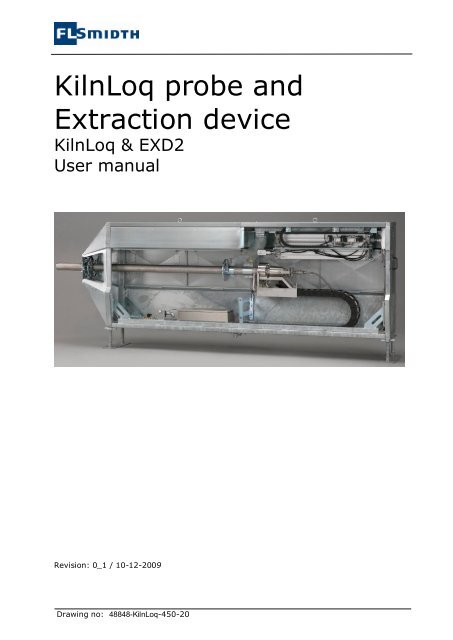
<strong>KilnLoq</strong> <strong>probe</strong> <strong>and</strong><strong>Extraction</strong> <strong>device</strong><strong>KilnLoq</strong> & EXD2User manualRevision: 0_1 / 10-12-2009Drawing no: 48848-<strong>KilnLoq</strong>-450-20
Unit Operation Instruction<strong>KilnLoq</strong> <strong>probe</strong> & EXD8.2.4 INSTALLATION OF PIPE LINES FOR COOLING WATER 168.2.5 INSTALLATION OF HEATED SAMPLE LINE 168.2.6 INSTALLATION OF SIGNAL AND POWER CABLES 168.3 FUNCTION DESCRIPTION EXTRACTION DEVICE 178.3.1 AUTOMATIC INSERTION AND EXTRACTION OF KILNLOQ PROBE 178.3.2 MANUAL INSERTION AND EXTRACTION OF KILNLOQ PROBE 178.3.3 POSITION STOP SYSTEM 178.3.4 FUNCTION 178.3.5 ADJUSTMENT 178.3.6 EXTRACTION OF PROBE DURING POWER FAILURE 188.3.7 FLANGE CLEANING SYSTEM 188.3.8 EXTRACTION DEVICE ACCESSORIES 188.4 COMMISSIONING OF EXTRACTION DEVICE 198.5 CLOSING DOWN OF EXTRACTION DEVICE 198.6 MANUALLY PULL OUT OF KILNLOQ PROBE 198.7 DISMOUNTING OF THE EXTRACTION DEVICE 209 OPTIONS................................................................................................................229.1 MANUAL EXD 229.2 MANUAL PROBE KIT 2210 MAINTENANCE .........................................................................................................2310.1 MAINTENANCE OF KILNLOQ PROBE 2310.1.1 GENERAL 2310.1.2 LEAK TEST 2310.1.3 CLEANING OF HEATED SAMPLE PIPE 2310.1.4 CLEANING OF FILTER 2310.1.5 REPLACEMENT OF FILTER O-RINGS 2310.1.6 REPLACEMENT OF HEATED SAMPLE PIPE 2410.1.7 REPLACEMENT OF COOLING JACKET 2410.2 DISMOUNTING THE KILNLOQ PROBE 2510.3 MAINTENANCE PROGRAM OF THE KILNLOQ PROBE 2510.4 MAINTENANCE OF EXTRACTION DEVICE 2510.4.1 CLEANING OF BOGIE RUNWAY 2510.4.2 REPLACEMENT OF AIR FILTER ELEMENT C4.1 IN FLANGE CLEANING SYSTEM 2510.5 MAINTENANCE PROGRAM OF THE EXTRACTION DEVICE 2611 TROUBLE SHOOTING ..................................................................................................2612 CONTACT INFO.........................................................................................................2613 DOCUMENT REVISION ................................................................................................26Page 2 of 27
Unit Operation Instruction<strong>KilnLoq</strong> <strong>probe</strong> & EXD1.1 APPENDIXAccording to “Document list: Unit Manual” <strong>and</strong> contains(Appendix is found directly after this operating instruction)Drawings according to “Document list: Unit Manual”Circuit diagramPart list1.2 SERIAL NUMBERSThis manual is specifically related to the following unit serial numbersThis manual covers <strong>KilnLoq</strong> serial numbersfromThis manual covers EXD serial numbersfrom48848-01 <strong>and</strong> forward51957-01 <strong>and</strong> forwardThe serial number follows the terms like: 5xxxx-yy where 5xxxx indicates serial lot number.The “yy” is a unique unit number(Documents revision history versus serial numbers is found in section 0)The serial number is tagged on each unit with a stainless steel plate on front of frame orsimilar.Page 3 of 27
Unit Operation Instruction<strong>KilnLoq</strong> <strong>probe</strong> & EXD2 PREFACEThis operating instruction is called a unit manual. The operating instruction covers only thisparticnular unit with respect to technical data, installation, use etc. This specific unit is apart of a complete system. Control <strong>and</strong> interaction in the specific system may varyaccording to system dem<strong>and</strong>s.The <strong>KilnLoq</strong> Probe is to be used with FLSmidth analysis system. The Probe comprises aProbe, piping, Filter, connections among others.Further more this instruction covers the <strong>Extraction</strong> <strong>device</strong> version 2 (EXD2) that is dedicatedto support <strong>and</strong> protect the <strong>KilnLoq</strong> <strong>probe</strong>.The system interaction with the <strong>KilnLoq</strong>-Probe is described in the system manual. Thedocument overview is to be found in section 2.1.The whole analysis system is to be operated <strong>and</strong> maintained as described in the systemmanual. If not, the efficiency <strong>and</strong> lifetime of the system will be reduced. An alarm mustalways be corrected at once. Qualified <strong>and</strong> trained personnel must perform themaintenance.2.1 DOCUMENT MAPThis manual is to be considered as part of the complete system documentation. A completeset of system documentation for an FLSmidth gas analysis system may comprise:User manuals (Binder) (all project specific drawings, list etc.) includingSystem data sheet covers project specific data.System operation instructionsUnit operating instructions (this document among others)Drawings, lists etc.Data sheets (Binder)Sub supplier’s manuals <strong>and</strong> datasheets2.2 DEFINITIONS AND TERMS2.2.1 GENERALSystem (analysis system)The complete analysis system which includes this unit amongothersSystem manualThe manual covering system function <strong>and</strong> interaction with this unitSystem datasheetOverall system data where all technical data <strong>and</strong> units are identifiedUnit manualAn operating instruction for a specific unit (Part of complete system. E.g. for aProbe)GMU <strong>Gas</strong> Monitoring Unit: Cabinet or housing comprising analysis parts, power distribution<strong>and</strong> control.CUBE FLSmidth analysis housing insulated, heated, cooled <strong>and</strong> with GMU installed.Trained/qualified PersonnelIndicates personnel that is not only certified to work on the plantaccording to all local <strong>and</strong> national regulations, but personnel who also has specific trainingfrom FLSmidth in use <strong>and</strong> maintenance of gas analysis systems.2.2.2 UNITS AND CONVERSION FACTORSAll units in FLSmidth <strong>Gas</strong> <strong>Analysis</strong> Technology documentation are SI-units except from:Pressure:BarTemperature:°C (degrees Celsius)Page 4 of 27
Unit Operation Instruction<strong>KilnLoq</strong> <strong>probe</strong> & EXDFor general use the following approximations can be used for conversion:Length: mm to inch factor 0,04Pressure: Bar to PSI (US) factor 14,5Temperature: °C to °F °F = °C × 1.8 + 322.2.3 KILNLOQ PROBE<strong>KilnLoq</strong>EXD2One-pipeProbeBBFilterThe Br<strong>and</strong> for FLSmidths One-pipe Kiln Inlet <strong>probe</strong>EXtraction Device v.2 for <strong>KilnLoq</strong> <strong>probe</strong>.Patent pending one-pipe design from process through filter.Extracts sample gas from a specific point in process.Blow-back cleaning air for filter cleaning.Filters sample gas from dust particles to protect the system.2.3 HOW TO READ THIS MANUALRead the instructions in this manual carefully before installing the system.FLSmidth A/S <strong>Gas</strong> <strong>Analysis</strong> Technology cannot accept any liability for damagesdue to non-observance of this manual.Sign:Before doing anything to the system, read warnings in section 2.4.This manual must be used in conjunction with the appendix. The document map in section2.1 shows an overview of the complete gas analysis system. This document covers theSDSP Probe only. For e.g. electrical wiring, the reader must use the appendix “Circuitdiagram”. All issues related to system performance must be found in the system manual.No part of this manual may be reproduced or transmitted in any form or by any means,electronic or printed, without the prior written permission of FLSmidth A/S. If this manual istranslated, the English version is to be considered as the original one.2.4 WARNINGS2.4.1 WARNING – HAZARDOUS VOLTAGES!Sign:All electrical installations must be in accordance with national <strong>and</strong> local regulations, <strong>and</strong>qualified personnel who are aware of these regulations must perform the electricalinstallation.Voltage must not be applied to the system until all electrical connections have been made<strong>and</strong> checked <strong>and</strong> then only by qualified personnel who are aware of the risks involved.Any disconnection of the earthed conductor inside or outside the <strong>device</strong> or the release of theearthed conductor connection can make the <strong>device</strong> hazardous to life. Deliberatedisconnection is inadmissible/prohibited.All connections must be made in accordance with the drawings in this manual.Page 5 of 27
Unit Operation Instruction<strong>KilnLoq</strong> <strong>probe</strong> & EXD2.4.2 WARNING – TOXIC, EXPLOSIVE GASESSign:Be sure to observe the safety regulations for the respective gases (sample gas <strong>and</strong> testgases/span gases) <strong>and</strong> test gas cylinders! The gas outlet should be led to ambient air toavoid danger to operators.Inflammable or explosive gas mixtures must not be introduced into the analysis systemunless the system is designed for the application.To avoid danger to operators by explosive, toxic or unhealthy gas components, flush thegas lines with ambient air or nitrogen before cleaning or exchange parts of the gas paths.2.4.3 WARNING - ACIDSSign:To avoid danger to operators by acid droplets build up in gas lines, first flush the gas linesbefore cleaning or exchange parts of the gas paths.Always use skin <strong>and</strong> eye protection before cleaning or exchanging parts of the gas pathsincluding condensate trap.2.4.4 WARNING - BURNSSign:To avoid the danger of operators getting burned due to high temperatures of <strong>probe</strong> <strong>and</strong>other components, the dem<strong>and</strong>s of occupational health regulations should be followed.Always plug the hole to the process when the <strong>probe</strong> is removed from the flange. The plugmust be secured with the lock pin.2.4.5 WARNING - PRESSUREESign:To avoid danger to operator the hoses must be without pressure before dismounting of anyconnections or hoses.2.4.6 WARNING – MOVING MACHINERYSign:Do not remove covers from <strong>Extraction</strong> Device with compressed air pressure to <strong>Extraction</strong>Device.Page 6 of 27
Unit Operation Instruction<strong>KilnLoq</strong> <strong>probe</strong> & EXD3 TECHNICAL INFORMATION3.1 TECHNICAL INFORMATION KILNLOQ PROBEDimensions:LengthHeight (filter house cover):Width (filter house cover):Sample end length:Available length for insertion in process:Diameter in process:Sample Filter:MaterialFilter sizeNOTE: Lengths depending on specific sampleend length.2000-4000mm400mm230mm1500/2500/3000/3700 mm1000/2000/2500/3200 mm (from EXD processflange)90 mmAISI 316L20µm ,102xØ50/40Process conditions:Measuring points:Kiln inlet or similarTemperature Max. 1200°CDust load Max. 1000 g/m 3Weight:Weight, dry:150 kgTemperatures:Ambient temperature: -10°C to 55°C 1Storage temperature: -15°C to 60°CEquipment must be protected against heatradiationPower supply:Power supply from GMU:Connections:Sample line connection:380-460 VAC, 2,5 kWPlease see “System Data sheet” for specificproject.6 mm stainless steel Swagelok1 Probe must be protected to prevent condensation <strong>and</strong> freezing.Page 7 of 27
Unit Operation Instruction<strong>KilnLoq</strong> <strong>probe</strong> & EXDBlow Back hoses (Cleaning Air)Cooling water connection:Flange for mounting <strong>probe</strong>10 mm stainless steel SwagelokISO 7/1-Rp-1 Union(1”female pipe tread)See Drawing “<strong>KilnLoq</strong> <strong>probe</strong>” <strong>and</strong> EXD2Mating Flange is NOT supplied by FLSmidth A/S3.2 TECHNICAL INFORMATION KILNLOQ 400 PROBEDimensions:LengthHeight (filter house cover):Width (filter house cover):Sample end length:Available length for insertion in process:Diameter in process:Sample Filter:MaterialFilter sizeNOTE: Lengths depending on specific sampleend length.2000-4000mm400mm230mm1500/2500/3000/3700 mm1000/2000/2500/3200 mm (from EXD processflange)90 mmAISI 316L20µm ,102xØ50/40Process conditions:Measuring points:Kiln inlet or similarTemperature Max. 400°CDust load Max. 1000 g/m 3Weight:Weight, dry:150 kgTemperatures:Ambient temperature: -10°C to 55°C 2Storage temperature: -15°C to 60°CEquipment must be protected against heatradiationPower supply:Power supply from GMU:380-460 VAC, 2,5 kWPlease see “System Data sheet” for specificproject.2 Probe must be protected to prevent condensation <strong>and</strong> freezing.Page 8 of 27
Unit Operation Instruction<strong>KilnLoq</strong> <strong>probe</strong> & EXDConnections:Sample line connection:Blow Back hoses (Cleaning Air)Cooling water connection:Flange for mounting <strong>probe</strong>6 mm stainless steel Swagelok10 mm stainless steel SwagelokNoneSee Drawing “<strong>KilnLoq</strong> <strong>probe</strong>” <strong>and</strong> EXD2Mating Flange is NOT supplied by FLSmidth A/S3.3 PHYSICAL DISTANCE BETWEEN EQUIPMENTThis information is covered by the system manual.4 INSTALLATION OF PROBESee layout drawing “System View”4.1 BEFORE INSTALLATION4.1.1 TRANSPORTAll transport must be carried out according to local regulations. Transport may be doneeither with equipment in transport box or unpacked. When equipment is still in a box, itmay be moved by st<strong>and</strong>ard fork lift.When unpacked, the Probe is easily h<strong>and</strong>led manually.It is highly recommended to unpack equipment as close as possible to installation point toprotect against damage during storage <strong>and</strong> transport.4.1.2 UNPACKINGBefore installation equipment must be unpacked, the wood box must be opened with acrowbar, or e.g. a circular saw (buzz saw) may be used to open the seaworthy box. The sawmust be carefully adjusted to a cutting dept of max. 2 mm though wood panels to avoiddamage of equipment.4.2 INSTALLATION OF KILNLOQ PROBEThe <strong>KilnLoq</strong> <strong>probe</strong> is from the factory installed in the extraction <strong>device</strong>.Page 9 of 27
Unit Operation Instruction<strong>KilnLoq</strong> <strong>probe</strong> & EXD5 SAFETY INSTRUCTIONSafety procedure before work on ProbeIssue:Procedure:Stop systemStop system according to the system manual.Test modeSet system is in test mode, <strong>and</strong> disables all alarms to CCSaccording to the system manual.Shut off power supplyShut off all electrical power sources from system GMUaccording to system manual.Shut off the air supplyClose valve V2.3 on the PCP. This will blow down thepressure in e.g. the extraction cylinders. Install padlockto secure valve.Secure <strong>KilnLoq</strong> <strong>probe</strong>Move lock <strong>device</strong> for <strong>probe</strong> bogie from “Bogie free” to“Bogie locked”. Install padlock to secure lock <strong>device</strong>.Remove coversRemove covers from <strong>Extraction</strong> Device.Perform work on ProbeRemove covers etc. from unit.Safety procedure after work on <strong>KilnLoq</strong> <strong>probe</strong>Issue:Procedure:Install coversInstall covers on <strong>Extraction</strong> Device.Remove <strong>probe</strong> lock <strong>device</strong> Remove padlock. Move lock <strong>device</strong> for <strong>probe</strong> bogie from“Bogie locked” to “Bogie free”.Open air supplyRemove padlock. Open valve V2.3 on the PCP.Test mode offAcknowledge active alarms if any <strong>and</strong> press “Test Off”. Seesection “System Manual” for HMI operation.Start systemPress “Start On” on the HMI. The system starts, <strong>and</strong> the<strong>probe</strong> moves in.See section “System Manual” for HMI operation.Safety procedure before work on <strong>KilnLoq</strong> <strong>probe</strong>Page 10 of 27
Unit Operation Instruction<strong>KilnLoq</strong> <strong>probe</strong> & EXD6 FUNCTION DESCRIPTION OF KILNLOQSee layout drawing “SDSP Probe”6.1 UNIT OVERVIEWEXD2<strong>KilnLoq</strong>Sample end<strong>KilnLoq</strong>ProbeFilterHouseProcessconnectionElectricalterminalsPic 1 <strong>KilnLoq</strong> & EXD26.2 PARTSSamplehose, BBhose <strong>and</strong> waterconnecetionsTag number Type FunctionW1 Probe Probe default tag numberDetailed view with subparts can be seen on drawing “<strong>KilnLoq</strong> Probe”6.3 FUNCTION DESCRIPTION PROBE6.3.1 GENERALThe main function of the <strong>KilnLoq</strong> <strong>probe</strong> is to take the sample gas from the cement process,clean it from dust <strong>and</strong> send it to the gas analyzers with out plugging up with dust <strong>and</strong>condensate. Basically the <strong>KilnLoq</strong> <strong>probe</strong> consists of three main components: coolingjacket, heated sample pipe <strong>and</strong> filter house.6.3.2 COOLING JACKETThe purpose with the cooling jacket is to serves mechanical <strong>and</strong> thermal protection for theheated pipe. The cooling jacket consists of three stainless steel pipes <strong>and</strong> two flanges allassembled to one piece. The cooling jacket has two pipe stubs for cooling water in- <strong>and</strong>outlet. To avoid mechanical tensions each of the three pipes are “fixed” in only one end. Thecooling jacket is not directly in contact with the sample gas, why there are no specialrequirements for the water temperature in this matter. The cooling jacket is mechanicallyprotected by the cooling water why the absolute maximum water temperature is 100 C°(212 F). In the rear flange of the cooling jacket there are installed two o-rings. Betweenthese o-rings there is an 8 mm drain <strong>and</strong> if an internal leakage occurs water will drop outhere. The “cold” inlet water is connected to the “chamber” near the diametric periphery ofPage 11 of 27
Unit Operation Instruction<strong>KilnLoq</strong> <strong>probe</strong> & EXDthe cooling jacket. The hot water returns by the centre “chamber” <strong>and</strong> exits the wateroutlet.6.3.3 HEATED SAMPLE PIPEThe purpose with the heated pipe is to transport the sample gas from the cement process tothe filter house. The heated sample pipe consists of a stainless inner pipe, heating cable,insulation material <strong>and</strong> an outer pipe assembled with two flanges. The power supply for theheating cables enters between the two flanges. To avoid mechanical tensions the inner pipeis “fixed” in only one end. To avoid condensation, the temperature of the gas path throughthe heated pipe is controlled by the <strong>Gas</strong> Monitoring Unit. The temperature set point isadjusted on the temperature controller for heated sample pipe. The controller is located inthe <strong>Gas</strong> Monitoring Unit <strong>and</strong> the default temperature setting is found in data sheets.6.3.4 FILTER HOUSEThe purpose with the filter house is to clean the sample gas from dust before it enters theheated sample hose to the <strong>Gas</strong> Monitoring Unit. The filter house consists of a stainlesshouse, lid <strong>and</strong> filter. The house is bolted directly to the heated sample pipe <strong>and</strong> sealed withan O-ring. The house is heated with four heating elements <strong>and</strong> it contains connectors forblow back air <strong>and</strong> sample hose. The stainless sintered filter is fixed only in the removablelid. This gives easy maintenance <strong>and</strong> allows the filter to extend when the house is heated.To avoid condensation, the temperature of the filter house is controlled by the <strong>Gas</strong>Monitoring Unit. The temperature set point is adjusted on the temperature controller forfilter house. The controller is located in the <strong>Gas</strong> Monitoring Unit <strong>and</strong> the default temperaturesetting is found in data sheets.6.3.5 FUNCTIONIn normal operation the gas flows through the heated pipe to the filter house, through thefilter <strong>and</strong> out to the heated sample hose. The dust is then collected at the inside of thesintered filter. After a pre-adjusted duration the sample stops <strong>and</strong> the filter is cleaned bycompressed air connected to the filter house <strong>and</strong> lid. To avoid condensation, thetemperature of the entire gas path through the <strong>KilnLoq</strong> <strong>probe</strong> is controlled by the <strong>Gas</strong>Monitoring Unit.6.3.6 COOLING JACKET TIP CLEANING SYSTEMIn order to keep the cooling jacket tip clean from build up the system can be equipped witha cooling jacket cleaner.The cooling jacket cleaner consists of valve that controls airflow. Cooling jacket cleaning isperformed during <strong>probe</strong> cleaning sequence. Air is lead between the inner of cooling jacket<strong>and</strong> Heated pipe approximately 1-8 seconds during first part of cleaning sequence.Page 12 of 27
Unit Operation Instruction<strong>KilnLoq</strong> <strong>probe</strong> & EXD7 COMMISSIONING OF KILNLOQ PROBEIn order to make commissioning on the <strong>KilnLoq</strong> <strong>probe</strong> the covers on the <strong>Extraction</strong> Devicemust be removed. Since the moving machinery can be hazardous to the human body,Please read safety procedure in section 4.2 that must be followed every time the <strong>KilnLoq</strong><strong>probe</strong> is to be accessed.7.1 INSERTION LENGTHOnly the insertion length of the <strong>probe</strong> has to be optimized on site. To adjust the insertionlength, undo the 6 bolts on the <strong>probe</strong> holder <strong>and</strong> slide the <strong>probe</strong> to the wanted position. Theoptimal insertion length is the minimum insertion where the gas intake is free to samplepure process gas with no interference from kiln sealing, <strong>probe</strong> flange etc. To find thisposition the <strong>KilnLoq</strong> <strong>probe</strong> can be operated manually in <strong>and</strong> out while the oxygen readingfrom the kiln is recorded. When the insertion is too small the oxygen will increasedramatically. To operate the <strong>probe</strong> manually in <strong>and</strong> out see section “System Manual”7.1.1 PROCEDURE FOR INSERTION ADJUSTMENTOperate <strong>probe</strong> manually to find optimal insertion.Carry out “Safety procedure before work on <strong>KilnLoq</strong> <strong>probe</strong>”Adjust insertion.Carry out “Safety procedure after work on <strong>KilnLoq</strong> <strong>probe</strong>”After adjusting the insertion length the removable flange cover must be positioned <strong>and</strong> fixedon the cooling jacket. In order to do this the cover must be moved down to the matingflange while the <strong>KilnLoq</strong> <strong>probe</strong> is still in the “out” position. The two finger screws on thecover should now be tighten with easy h<strong>and</strong> thus the cover still is free to move but a certainfriction is present to keep the cover from moving by it self. The <strong>KilnLoq</strong> <strong>probe</strong> should nowbe operated in (to the mechanical stop) <strong>and</strong> out thus the cover finds the right position.Tighten the finger screws thus the cover is fixed on the cooling jacket.Procedure for cover adjustment:Carry out “Safety procedure before work on <strong>KilnLoq</strong> <strong>probe</strong>”Move cover to mating flange <strong>and</strong> tight screws easily.Carry out “Safety procedure after work on <strong>KilnLoq</strong> <strong>probe</strong>”Operate <strong>KilnLoq</strong> <strong>probe</strong> in <strong>and</strong> out. See section “System Operating instruction” for HMIoperation.Carry out “Safety procedure before work on <strong>KilnLoq</strong> <strong>probe</strong>”Tighten the finger screws.Carry out “Safety procedure after work on <strong>KilnLoq</strong> <strong>probe</strong>”After work on the <strong>KilnLoq</strong> <strong>probe</strong> the covers must be reinstalled on the <strong>Extraction</strong> Device.7.2 CLOSING DOWN OF KILNLOQ PROBEIf the <strong>KilnLoq</strong> <strong>probe</strong> has to be out of service for a longer period the <strong>probe</strong> must be closeddown as listed.Closing down <strong>KilnLoq</strong> <strong>probe</strong>Issue:Stop systemSecure <strong>KilnLoq</strong> <strong>probe</strong>Shut off the air supplyProcedure:Press “Start Off” on the HMI. The system stops, <strong>and</strong> the <strong>probe</strong>moves out. See section “System Manual” for HMI operation.Move lock <strong>device</strong> for <strong>probe</strong> bogie from “Bogie free” to “Bogielocked”. Install padlock to secure lock <strong>device</strong>.Close valve V2.3 on the PCP. Install padlock to secure valve.Page 13 of 27
Unit Operation Instruction<strong>KilnLoq</strong> <strong>probe</strong> & EXDClosing down <strong>KilnLoq</strong> <strong>probe</strong>Issue:Stop water coolingSwitch off <strong>probe</strong> heatersShut off flange cleanerProcedure:Switch off “Main switch” on the Water Control Panel <strong>and</strong> closevalve V3.2Switch off filter heater E3 <strong>and</strong> pipe heater E4 on respectivebreakers in the GMU. This is done according to circuit diagram.Close valve V4.6 for flange cleaner (on <strong>Extraction</strong> Device)Page 14 of 27
Unit Operation Instruction<strong>KilnLoq</strong> <strong>probe</strong> & EXD8 EXTRACTION DEVICE (EXD)See layout drawing “EXD: <strong>Extraction</strong> <strong>device</strong>”8.1 GENERAL INFORMATION EXTRACTION DEVICEThe purpose of the <strong>Extraction</strong> Device is automatically extraction <strong>and</strong> insertion of the <strong>probe</strong>.The extraction <strong>device</strong> is one unit containing: pneumatic cylinders, <strong>KilnLoq</strong> <strong>probe</strong>, controlvalves <strong>and</strong> a mechanical protecting covers for personal protection. The <strong>Extraction</strong> Device iscontrolled from the <strong>Gas</strong> Monitoring Unit (GMU).8.1.1 TECHNICAL INFORMATION EXTRACTION DEVICEDimensions:Dimensions lx w x hDimensions seaworthy package l x w x hNOTE: Lengths depending on specific Probelength <strong>and</strong> project order.2575-5138 x 472 x 1291 mm.3000-5600 x 700 x 1600 mm.Weight:Weight, dry:Weight seaworthy package gross dryApp. 600 kg.App. 700 kg.Temperatures:Ambient temperature:Storage temperature:Power supply:Power supply from GMU: (control valves) 24 V DC, 25 W.Power supply from GMU: (<strong>KilnLoq</strong> <strong>probe</strong>) 380-460 VAC, 2,5 kWCompressed air:Pressure:Consumption:Quality:Connections:Air connection:Water connection:600 kPa3 Nm 3 /h at 600 kPa3-3-3 according to ISO 8573-1Maximum 5 m (size) 5 mg/m 3 particlesMinimum -20° water dew pointMaximum 1 mg/m 3 oilISO 7/1-Rp ½, Union (½”female pipe tread)ISO 7/1-Rp-1 Union(1”female pipe tread)8.2 INSTALLATION OF EXTRACTION DEVICESee layout drawings “<strong>KilnLoq</strong>: System View” <strong>and</strong> “<strong>KilnLoq</strong>: Mating Flange”8.2.1 INSTALLATION OF MATING FLANGEThe performance of the <strong>KilnLoq</strong> <strong>probe</strong> depends in a very high degree of the location <strong>and</strong>position of the mating flange. The mating flange must be positioned thus the <strong>KilnLoq</strong> <strong>probe</strong>is able to take a pure process gas sample with no interference from kiln sealing <strong>and</strong> themechanical protection is as good as possible. The installation is different from site to sitebut below listed items should be followed.The mating flange should be installed:At 45° to the kiln axis, as close as possible to the kiln seal thus the gas intake protrudespast the kiln seal <strong>and</strong> leakage from the seal does not affect the measurement.Page 15 of 27
Unit Operation Instruction<strong>KilnLoq</strong> <strong>probe</strong> & EXDIn the kiln centre line, away from the affects of the raw material feeders <strong>and</strong> away from theaffects of any air blaster’s etc.At an angle of approx. 0-10° downwards towards the gas intake. See drawing “EXD:<strong>Extraction</strong> <strong>device</strong>”8.2.2 INSTALLATION OF EXTRACTION DEVICEThe <strong>Extraction</strong> Device must be positioned thus the bolt flange fits the mating flange. Thetwo adjustable support feet under the <strong>Extraction</strong> Device must be adjusted thus it is inhorizontal position along <strong>and</strong> across the vessel. The <strong>Extraction</strong> Device must now be boltedto the mating flange <strong>and</strong> fundament.8.2.3 CONNECTION OF AIR HOSES.See layout drawing “KILNLOQ: P&I Diagram”The <strong>Extraction</strong> Device needs compressed air for the pneumatic cylinders, flange cleaningsystem <strong>and</strong> for cleaning the <strong>KilnLoq</strong> <strong>probe</strong>. From the factory all hoses are connected on the<strong>Extraction</strong> Device <strong>and</strong> only have to be connected to the Probe Cleaning Panel. All four hosesare at the end tagged with small metal plates an must be connected according to followingtable<strong>Extraction</strong> Device“BB1” <strong>KilnLoq</strong> <strong>probe</strong> under filter house“BB2” <strong>KilnLoq</strong> <strong>probe</strong> at snap connector“AS2” <strong>Extraction</strong> Device at pneumatic cylinders“AS3” <strong>Extraction</strong> Device at flange cleanerProbe Cleaning Panel10 mm bulkhead labelled “BB1” (instrumentair)10 mm bulkhead labelled “BB2” (instrumentair)10 mm bulkhead labelled “AS2” (instrumentair)½” union labelled “AS3” or plants working air(cheap air)IMPORTANT!The flexible hoses must be mechanical protected <strong>and</strong> installed thus bends are avoided.8.2.4 INSTALLATION OF PIPE LINES FOR COOLING WATERSee layout drawing “KILNLOQ: P&I Diagram”The two 1” unions tagged “WL1” <strong>and</strong> “WL2” must be connected to the unions with sametags on the Water Control Panel. The fixed pipe line must be carried out in 1” galvanizedtube. No insulation is required. Lines must be connected according to following table:<strong>Extraction</strong> DeviceWater Control Panel1” union labelled “WL1” 1” union labelled “WL1”1” union labelled “WL2” 1” union labelled “WL2”8.2.5 INSTALLATION OF HEATED SAMPLE LINESee layout drawing “KILNLOQ: P&I Diagram”The heated sample hose is from the factory installed on the <strong>KilnLoq</strong> <strong>probe</strong>. For furtherinformation see “System manual”8.2.6 INSTALLATION OF SIGNAL AND POWER CABLESIn the bottom of the <strong>Extraction</strong> Device there is a stainless terminal box. The box is equippedwith cable gl<strong>and</strong>s for needed cables. Cables must be connected according to section “Cablelist” in “System manual”.Page 16 of 27
Unit Operation Instruction<strong>KilnLoq</strong> <strong>probe</strong> & EXD8.3 FUNCTION DESCRIPTION EXTRACTION DEVICE8.3.1 AUTOMATIC INSERTION AND EXTRACTION OF KILNLOQ PROBE<strong>Extraction</strong> <strong>and</strong> insertion of <strong>probe</strong> is controlled by the GMU. Pneumatic cylinders M4.1 <strong>and</strong>M4.2 perform the mechanical stroke. The <strong>probe</strong> is inserted when the system is started <strong>and</strong>there is no unit alarm. The <strong>probe</strong> is extracted if a unit alarm occurs. Furthermore the <strong>probe</strong>is extracted once every 6 th cleaning (default setting) of <strong>probe</strong> to remove any materials builtup on <strong>probe</strong>.There are three position switches 1B6 (position IN) <strong>and</strong> 1B8/1B9 (position OUT). They areused to indicate end positions of the cylinders.8.3.2 MANUAL INSERTION AND EXTRACTION OF KILNLOQ PROBEWhen the system is in test mode <strong>and</strong> the <strong>Extraction</strong> Device is switched to manual operation,see “System manual”, it is possible to move the <strong>probe</strong> in <strong>and</strong> out by means of the two pushbuttons located at the back end of the EXD. When the push buttons are active the indicationlamps inside will light up. If a Unit alarm is active it is still possible to insert the <strong>KilnLoq</strong><strong>probe</strong> with the “IN” button but when the button is released the <strong>probe</strong> moves automaticallyout. This gives the opportunity to move the <strong>probe</strong> during Unit alarm but it does not allowthe <strong>probe</strong> to be left in the kiln with out cooling water.8.3.3 POSITION STOP SYSTEMWith the position stop system it is possible to adjust the insertion length of the <strong>KilnLoq</strong><strong>probe</strong>. The purpose with the system is to keep the insertion as short as possible in order toincrease life time <strong>and</strong> performance of the sample end. The system consists ofThe adjustable lid mounted on the sample endA Movable boogie stop with two shock absorbers on I-profil. (4 steps of 0,3m)Sensor bar with step less adjustable sensor plate.Inductive sensor on filter housing.8.3.4 FUNCTIONWhen the <strong>probe</strong> moves in, the wheel boogie hits the shock absorbers <strong>and</strong> thus the boogiestop, when the decided insertion is achieved. The shock absorbers take down the velocity ofthe <strong>KilnLoq</strong> <strong>probe</strong> thus it hits the stop in a smooth way. When <strong>probe</strong> is in place the inductivesensor senses the sensor plate on sensor bar. The inductive sensor gives the position signalto the PLC. The adjustable lid seals to inner flange on EXD <strong>and</strong> thereby seals to process gas.The adjustable lid is fixed on the sample end.8.3.5 ADJUSTMENT8.3.5.1 To find the optimal insertion, the kiln must be running in a stable <strong>and</strong>“well known” condition. The extraction <strong>device</strong> must be switched to manualmode thus it is possible to move the <strong>probe</strong> in <strong>and</strong> out by mean of the pushbuttons on the extraction <strong>device</strong>. The gas sample pump must be runningthus the actual oxygen value from the kiln can be recorded on theanalyzer. To adjust the insertion:Start the <strong>KilnLoq</strong> system, see “System manual”Set system to test mode, see “System manual”Set extraction <strong>device</strong> to manual operation, see “System manual”. The push buttons on theextraction <strong>device</strong> lights up.Wait until the oxygen reading is stableUse the push buttons on the extraction <strong>device</strong> to move the <strong>probe</strong> out, in small steps at 10cm.Page 17 of 27
Unit Operation Instruction<strong>KilnLoq</strong> <strong>probe</strong> & EXDMonitor the oxygen level at each step.Determine at which step the oxygen value suddenly increases dramatically. Make a mark.Move the <strong>probe</strong> out to the end position.Use the push buttons on the extraction <strong>device</strong> to move the <strong>probe</strong> in, in small steps at 10cm.Monitor the oxygen level at each step.Determine at which step the oxygen value suddenly decreases dramatically. Make a mark.Move the <strong>probe</strong> to the mark nearest the kiln <strong>and</strong> then move the <strong>probe</strong> further 40cm into thekiln <strong>and</strong> make a mark. (Optimal insertion point archived!System is now ready to be adjusted!Stop system <strong>and</strong> prepare <strong>probe</strong> as described in section 8.6Remove side covers on the extraction <strong>device</strong>.Move the Moveable boogie stop with shock absorbers to nearest position against wheelboogie.Move boogie to contact boogie stop. (Shock absorbers compressed)Fine tune <strong>probe</strong> position by moving <strong>probe</strong> in <strong>probe</strong> clamp.Adjust sensor plate to activate position sensor 1B6.Move the adjustable lid against the entrance flange <strong>and</strong> fix it.Put on side covers.Set system to analysis mode, see “System manual”.The <strong>probe</strong> is now approximately 40cm inside the edge where it takes false air from thesealing <strong>and</strong> entrance hole. Due to changes in the process <strong>and</strong> wear of the kiln sealing theposition must be fine adjusted from time to time.Caution:Since this test has to be done with the system running <strong>and</strong> the side covers removed it is forsafety reasons recommended to be two persons present.8.3.6 EXTRACTION OF PROBE DURING POWER FAILUREIf a power failure occurs the solenoid valve Y4.1 will open <strong>and</strong> compressed air forces thesolenoid valve Y4.1 to extraction position <strong>and</strong> the <strong>probe</strong> will be extracted from process.8.3.7 FLANGE CLEANING SYSTEMSee layout drawing “KILNLOQ: P&I Diagram”In order to keep the kiln entrance clean from raw materials the <strong>Extraction</strong> Device isequipped with a special cleaning system. The system consists of ball valve, air filter, shut offsolenoid <strong>and</strong> cleaning nozzles located on the entrance flange. Due to safety reasons thesolenoid only opens for cleaning air when the <strong>KilnLoq</strong> <strong>probe</strong> is automatically operated by the<strong>Gas</strong> Monitoring Unit. The cleaning air enters the entrance pipe with high speed <strong>and</strong>transports dust <strong>and</strong> smaller pieces of build-up back into the process. This Allows the <strong>KilnLoq</strong><strong>probe</strong> to operate smooth in <strong>and</strong> out through the entrance pipe.8.3.8 EXTRACTION DEVICE ACCESSORIESThe EXD is supplied with following accessories to easy <strong>and</strong> safe maintenance.8.3.8.1 Cleaning Lance & Safety blow off for quick connectorThe <strong>Extraction</strong> <strong>device</strong> is supplied with a Cleaning Lance. The cleaning lance are located inlover right sidepiece of EXD It is accessed by removing lower back shields. The purpose ofthe cleaning lance is to ensure optimal use of the unique <strong>KilnLoq</strong> one pipe concept. Thecleaning lance comprise of a 8mm stainless steel pipe, valve <strong>and</strong> connections. The cleaninglance is to be used in conjunction with the “Safety blow off for quick connector”.8.3.8.2 Safety blow off for quick connectorIn back end of <strong>Extraction</strong> <strong>device</strong> is a “Safety Blow Off for quick connector” (BO) located.Page 18 of 27
Unit Operation Instruction<strong>KilnLoq</strong> <strong>probe</strong> & EXDThe purpose of the “BO” is to ensure safe use of the cleaning lance. By leading return –back pressure (air <strong>and</strong> dust) away from operator during <strong>probe</strong> pipe cleaning. The “BO” isdesigned to fit directly on the male connector on <strong>KilnLoq</strong> filter house. By releasing thespring return clamps it can easily be put on the male connector <strong>and</strong> secured. Be sure not to“Push” the BO onto the connector, due to risk of scratching the sealing surface on Swagelokconnector.8.3.8.3 Air hoseOn <strong>Extraction</strong> <strong>device</strong> upper back shield is located an Air hose holder. The hose is 6m <strong>and</strong>intended to be used with above accessories. The air supply is found on the PCP.8.3.8.4 Use of Cleaning Lance & Safety blow off for quick connectorIn case of <strong>probe</strong> blockage follow the next few steps to archive easy <strong>probe</strong> cleaning.DANGER: The use of Cleaning Lance <strong>and</strong> Safety blow off is NOT a substitute forpersonal protection for hot <strong>and</strong> dusty work!Put system in testmode <strong>and</strong> sequre <strong>probe</strong> as decribed in section 4.2 <strong>and</strong> “System Manual”Remove the quick connector Kilnloq filterhousing.Mount the “Safety blow off for quick connector” on the male part off quick connector onfilterhouse.Insert lance connect air supply. Gently open valve to let compressed air blow out material in<strong>probe</strong>.Clean Probe until Cleaning lance can be fully inserted <strong>and</strong> moves “free”The lance becomes hot during the cleaning use proper protectionRemove lance <strong>and</strong> Safety blow off.Reconnect the quick connector Kilnloq filter housingPut system out of test mode <strong>and</strong> remove the safety features.Restart system as described in section “System Manual”8.4 COMMISSIONING OF EXTRACTION DEVICECheck following items:Mechanical installation (mating flange, foundation, position etc.)Connection of air supply according to 8.2.3Connection of water supply according to.8.2.4Connection of heated sample hose according to.8.2.5Connection of signal <strong>and</strong> power cables according to 8.2.6Open valve V4.6 for flange cleaning system.8.5 CLOSING DOWN OF EXTRACTION DEVICESee section 7.28.6 MANUALLY PULL OUT OF KILNLOQ PROBEThe <strong>probe</strong> can get locked inside the process due to material built up on the <strong>probe</strong>. If thematerials built up are preventing the extraction <strong>device</strong> to pull out the <strong>probe</strong>, this has to bedone manually according to the following table:Issue:Stop systemTest modeProcedure:Press “Start Off” on the HMI. See “<strong>KilnLoq</strong> system Users Manual”for HMI operation.Press “Test ON” on the HMI See “<strong>KilnLoq</strong> system Users Manual”for HMI operation.Page 19 of 27
Unit Operation Instruction<strong>KilnLoq</strong> <strong>probe</strong> & EXDIssue:Procedure:Manual EXD modePress ”Manual operation ON” on the HMI. See “<strong>KilnLoq</strong> systemUsers Manual” for HMI operation.Shut off the air supplyClose <strong>and</strong> lock valve V2.3 on the PCPEmpty the cylinder for air Press push button “IN”, let all air out of cylinder (no hissingsound)Press push button “OUT”, let all air out of cylinder (no hissingsound)Remove the coversRemover covers from <strong>Extraction</strong> DeviceDisconnect the air supply to Disconnect 8mm air hose on both ends of cylinder M4.1the cylinder Disconnect 8mm air hose on both ends of cylinder M4.2Pull the <strong>probe</strong> end out of Attach pulley-block to eyebolt on bogie <strong>and</strong> on to the end ofprocessEXD2Take care that the <strong>probe</strong> sample end <strong>and</strong> filter is not damagedby the chain/wireGently pull the <strong>probe</strong> out of the processSecure <strong>probe</strong>Move lock <strong>device</strong> for <strong>probe</strong> bogie from “Bogie free” to “Bogielocked”Clean the <strong>probe</strong>Clean the <strong>probe</strong> for any materials built up on the outsideReconnect the air supply to Connect 8mm air hose on both ends of cylinder M4.1the cylinder Connect 8mm air hose on both ends of cylinder M4.2Remount the coversMove lock <strong>device</strong> for <strong>probe</strong> bogie from “Bogie locked” to “Bogiefree”Install covers on the <strong>Extraction</strong> DeviceOpen air supplyOpen valve V2.3 on the PCPManual modeInsert <strong>and</strong> extract the <strong>probe</strong> in manual mode to see if it is OKTest mode offPress “Test Off” on the HMI. See “<strong>KilnLoq</strong> system Users Manual”for HMI operation.Start systemPress “Start ON” on the HMI. See “<strong>KilnLoq</strong> system Users Manual”for HMI operation.8.7 DISMOUNTING OF THE EXTRACTION DEVICETo dismount the extraction <strong>device</strong> follow this procedure.Issue:Stop systemTest modeShut off the air supplySecure the <strong>probe</strong> positionStop water coolingSwitch off <strong>probe</strong> heatersDisconnecting all hosesProcedure:Press “Start Off” on the HMI. See “<strong>KilnLoq</strong> system Users Manual”for HMI operation.Press “Test ON” on the HMI. See “<strong>KilnLoq</strong> system Users Manual”HMI operation.Close valve V2.3 on the PCPMove lock <strong>device</strong> for <strong>probe</strong> bogie from “Bogie free” to “Bogielocked”Remover covers from <strong>Extraction</strong> DeviceSwitch off “Main switch” on the Water Control Panel <strong>and</strong> closevalve V3.2Switch off filter heater E3 <strong>and</strong> pipe heater E4 on respectivebreakers in the GMU. This is done according to the circuitdiagram.Wait for the <strong>probe</strong>, heated hose <strong>and</strong> the cooling water to cooldownDisconnect air hosesDisconnect water hosesDisconnect Heated sample linePage 20 of 27
Unit Operation Instruction<strong>KilnLoq</strong> <strong>probe</strong> & EXDIssue:Dismount the <strong>Extraction</strong><strong>device</strong>Procedure:Dismount the communication cable to the GMU.NOTE: the GMU end must be disconnected first!Dismount the extraction <strong>device</strong> mechanicallyPage 21 of 27
Unit Operation Instruction<strong>KilnLoq</strong> <strong>probe</strong> & EXD9 OPTIONSFollowing options may be included in system on request. See “System Data Sheet” foroverview.9.1 MANUAL EXDFor <strong>KilnLoq</strong> 400 <strong>probe</strong>s it is possible to order an EXD without automatic <strong>probe</strong>extraction/insertion. The Probe is manually operated with a h<strong>and</strong>le on the cylinder boogie.All functions related to <strong>KilnLoq</strong> <strong>probe</strong> cleaning, position etc. are as for Automatic EXD.To move <strong>probe</strong> in <strong>and</strong> out of process open the backcover of EXD. Release h<strong>and</strong>le <strong>and</strong> pullback.9.2 MANUAL PROBE KIT“<strong>KilnLoq</strong>, 400 installation kit” part no. 105137 may be ordered with a <strong>KilnLoq</strong> 400 version.The kit is providing h<strong>and</strong>les <strong>and</strong> flanges for manually h<strong>and</strong>ling of <strong>probe</strong> by h<strong>and</strong>.No EXD is supplied.Page 22 of 27
Unit Operation Instruction<strong>KilnLoq</strong> <strong>probe</strong> & EXD10 MAINTENANCE10.1 MAINTENANCE OF KILNLOQ PROBE10.1.1 GENERALBecause of the simple construction of the <strong>KilnLoq</strong> <strong>probe</strong>, the regular maintenance work iskept to an absolute minimum. Only the filter <strong>and</strong> heated sample pipe have to be checkedfrom time to time.10.1.2 LEAK TESTTo prepare Kilnloq <strong>probe</strong> for Leak test perform following stepsFollow safety instructions for <strong>probe</strong> in section 4.2Disconnect snap connector BB2 at the end of the <strong>KilnLoq</strong> <strong>probe</strong>.Remove the white insulating cover.Use the h<strong>and</strong> wheels to take out the filter lid.Replace sintered steel filter with special leak test tool.Before assembling the O-rings should be verified. If needed, they must be replaced.Connect snap connector BB2.Perform Leak test as described in “System Manual”10.1.3 CLEANING OF HEATED SAMPLE PIPEThe heated sample pipe should only be cleaned if the alarm “P1.1 Low suction pressure” ispresent.To clean the heated sample pipe the <strong>KilnLoq</strong> <strong>probe</strong> must be securedDisconnect snap connector BB2 at the end of the <strong>KilnLoq</strong> <strong>probe</strong>. From the snap connectorthere is free access to the process.Clean the heated pipe with an 8mm rod or similar.When the gas path is clean, put back on the snap connector.IMPORTANT!In order to avoid dust entering the sample hose the filter must always be installed in the<strong>KilnLoq</strong> <strong>probe</strong> while cleaning the heated sample pipe.After work on the <strong>KilnLoq</strong> <strong>probe</strong> the covers must be reinstalled on the <strong>Extraction</strong> Device.10.1.4 CLEANING OF FILTERThe filter should only be cleaned if the alarm “P1.1 Low suction pressure” is present <strong>and</strong> theheated pipe has been cleaned as described above.To clean the filter the <strong>KilnLoq</strong> <strong>probe</strong> must be secured.Disconnect snap connector BB2 at the end of the <strong>KilnLoq</strong> <strong>probe</strong>.Remove the white insulating cover.Use the h<strong>and</strong> wheels to take out the filter lid.Clean the filter with compressed air.Before assembling the O-rings should be verified. If needed, they must be replaced.After work on the <strong>KilnLoq</strong> <strong>probe</strong> the covers must be reinstalled on the <strong>Extraction</strong> Device.10.1.5 REPLACEMENT OF FILTER O-RINGSIn order to maintain the high run factor the O-rings in the filter house should be replacedPage 23 of 27
Unit Operation Instruction<strong>KilnLoq</strong> <strong>probe</strong> & EXDevery 3 month. A complete filter kit with O-rings is available. The filter kit contains two O-rings for the filter, two O-rings for the filter lid <strong>and</strong> one O-ring for the snap connectorTo replace the O-rings the <strong>KilnLoq</strong> <strong>probe</strong> must be secured.Disconnect snap connector BB2 at the end of the <strong>KilnLoq</strong> <strong>probe</strong>.Remove the white insulating cover.Use the h<strong>and</strong> wheels to take out the filter lid.Cool down the filter <strong>and</strong> lid with compressed air.Remove old O-rings with a small screwdriver <strong>and</strong> install the new ones with no use oftools.IMPORTANT!Do not stretch the new O-rings too much. This could damage the O-rings while the filter lidis installed back on the filter house.After work on the <strong>KilnLoq</strong> <strong>probe</strong> the covers must be reinstalled on the <strong>Extraction</strong> Device.10.1.6 REPLACEMENT OF HEATED SAMPLE PIPETo replace the heated sample pipe the <strong>KilnLoq</strong> <strong>probe</strong> must be secured.Switch off power supply to filter heater E3 <strong>and</strong> pipe heater E4 according to circuit diagram.Disconnect heating elements <strong>and</strong> PT100 sensor for pipe heater E4 at terminal box (on<strong>Extraction</strong> Device) according to circuit diagram.Disconnect snap connector BB2 at the end of the <strong>KilnLoq</strong> <strong>probe</strong>.Remove the white insulating cover.Disconnect blow back hose BB1 <strong>and</strong> sample hose E1 under the filter house.Take out the four 16mm bolts <strong>and</strong> move the filter house back.Disconnect the earth wire on the flange of the heated sample pipe.Take out the four 16mm Allen bolts <strong>and</strong> remove the heated sample pipe in one piece. Ifnecessary remove the rear cover on the <strong>Extraction</strong> Device.Install the new heated pipe in opposite order.IMPORTANT!O-ring (between filter house <strong>and</strong> heated sample pipe) <strong>and</strong> gasket (between heated samplepipe <strong>and</strong> cooling jacket) must be replaced.After work on the <strong>KilnLoq</strong> <strong>probe</strong> the covers must be reinstalled on the <strong>Extraction</strong> Device.10.1.7 REPLACEMENT OF COOLING JACKETTo replace the cooling jacket the <strong>KilnLoq</strong> <strong>probe</strong> must be secured.Switch off power supply to filter heater E3 <strong>and</strong> pipe heater E4 according to circuit diagram.Disconnect heating elements <strong>and</strong> PT100 sensor for pipe heater E4 at terminal box (on<strong>Extraction</strong> Device) according to circuit diagram.Disconnect snap connector BB2 at the end of the <strong>KilnLoq</strong> <strong>probe</strong>.Remove the white insulating cover.Disconnect blow back hose BB1 <strong>and</strong> sample hose E1 under the filter house.Take out the four 16mm bolts <strong>and</strong> move the filter house back.Disconnect the earth wire on the flange of the heated sample pipe.Take out the four 16mm Allen bolts <strong>and</strong> remove the heated sample pipe in one piece.Make mechanically support (hanger or chain) for the filter house assembly thus it stays inright position when the cooling jacket is removed.Stop the water pump M3.1 (find breaker in circuit diagram for WCP) <strong>and</strong> close valve V3.2 onthe Water Control Panel.Disconnect the water hoses at the pipe stubs on the cooling jacket.Disconnect the earth wire on the flange of the cooling jacket.Take out the three 16mm bolts holding the filter house assembly on the flange of thePage 24 of 27
Unit Operation Instruction<strong>KilnLoq</strong> <strong>probe</strong> & EXDcooling jacket.Take out the 6 bolts on the <strong>probe</strong> holder <strong>and</strong> remove the cooling jacket.Close valve V4.6 for flange cleaner.Install the blind flange (located in the <strong>Extraction</strong> Device) on the entrance to the kiln.Install the new cooling jacket in opposite order10.2 DISMOUNTING THE KILNLOQ PROBESwitch off power supply to filter heater E3 <strong>and</strong> pipe heater E4 according to circuit diagram.Disconnect heating elements <strong>and</strong> PT100 sensor for filter heater E3 at terminal box (on<strong>Extraction</strong> Device) according to circuit diagram.Disconnect heating elements <strong>and</strong> PT100 sensor for pipe heater E4 at terminal box (on<strong>Extraction</strong> Device) according to circuit diagram.Disconnect snap connector BB2 at the end of the <strong>KilnLoq</strong> <strong>probe</strong>.Remove the white insulating cover.Disconnect blow back hose BB1 <strong>and</strong> sample hose E1 under the filter house.Disconnect all earth wires on the flanges of the <strong>KilnLoq</strong> <strong>probe</strong>.Stop the water pump M3.1 (find breaker in circuit diagram for WCP) <strong>and</strong> close valve V3.2 onthe Water Control Panel.Disconnect the water hoses at the pipe stubs on the cooling jacket.Take out the three 16mm bolts holding the filter house assembly on the flange of thecooling jacket.Take out the 6 bolts on the <strong>probe</strong> holder <strong>and</strong> remove the complete <strong>KilnLoq</strong> <strong>probe</strong>.Close valve V4.6 for flange cleaner.Install the blind flange (located in the <strong>Extraction</strong> Device) on the entrance to the kiln.Install the <strong>KilnLoq</strong> <strong>probe</strong> in opposite order.After work on the <strong>KilnLoq</strong> <strong>probe</strong> the covers must be reinstalled on the <strong>Extraction</strong> Device.10.3 MAINTENANCE PROGRAM OF THE KILNLOQ PROBERefer to section 10.1, to get instructions how to do the maintenance in the following table.Date /Initials Maintenance program D W M YO-ring 102934: replace two o-rings on filter holder.XO-ring kit 102957 for filter house: replace o-rings onfilter, filter holder <strong>and</strong> snap connector.1/4Sintered metal filter:ReplaceX10.4 MAINTENANCE OF EXTRACTION DEVICEAll ways perform work with safety in mind see section: 4.210.4.1 CLEANING OF BOGIE RUNWAYIn order to allow the bogie to move in <strong>and</strong> out the runway has to be kept clean from dust.To clean bogie runway the <strong>KilnLoq</strong> <strong>probe</strong> must be securedClean bogie runway with vacuum cleaner.After work on the <strong>KilnLoq</strong> <strong>probe</strong> the covers must be reinstalled on the <strong>Extraction</strong> Device.10.4.2 REPLACEMENT OF AIR FILTER ELEMENT C4.1 IN FLANGE CLEANING SYSTEMThe filter element has to be replaced every ½ yearTo replace filter element the <strong>KilnLoq</strong> <strong>probe</strong> must be securedPage 25 of 27
Unit Operation Instruction<strong>KilnLoq</strong> <strong>probe</strong> & EXDReplace filter element.After work on the <strong>KilnLoq</strong> <strong>probe</strong> the covers must be reinstalled on the <strong>Extraction</strong> Device.10.5 MAINTENANCE PROGRAM OF THE EXTRACTION DEVICERefer to section 10.4, to get instructions how to do the maintenance in the following table.Date /Initials Maintenance program D W M YBogie runway:XClean for dust with vacuum cleaner.Replace air filter C4.1½11 TROUBLE SHOOTINGAlarms may vary according to implementation in the system.Fault Meaning Probable cause SolutionFilterbloggingLow sample gasflow due toblockage on filterelementCondensation on pipe,filter element or fittingscollects condensate dueto low temperatureCheck all settings <strong>and</strong>verify temperatures.12 CONTACT INFO<strong>Gas</strong> <strong>Analysis</strong> TechnologyFLSmidth A/SKlostermarken 6DK-9550 Mariager · DenmarkTel.: +45 7010 2277 · Fax: +45 7010 2288Main e-mail: gas@flsmidth.comService e-mail: gas-service@flsmidth.comCVR-No. DK 1502 8882www.flsmidth.com/gas13 DOCUMENT REVISIONRev. Date Author Description Serial numberscovered0_1 10-12-2009 RBN Tip clean incl. 48848 <strong>and</strong> forward55291 <strong>and</strong> forward0 28-08-2009 RBN New doc. 48848 <strong>and</strong> forward51957 <strong>and</strong> forwardOldPage 26 of 27
Document List:Unit ManualRevision List: Unit ManualCustomer Drawing No.:EXD: Mating FlangeCustomer Drawing No.:S-GENERI--1-000-50S-GENERI--1-110-11Rev. Date. Ini. Remarks0 31-08-2009 RBNRev. Date. Ini. Remarks0 31-08-2009 RBN<strong>KilnLoq</strong> <strong>probe</strong>Customer Drawing No.:S-GENERI--1-120-10Rev. Date. Ini. Remarks0 31-08-2009 RBNEXD: <strong>Extraction</strong> <strong>device</strong> 2547Customer Drawing No.:EXD: <strong>Extraction</strong> <strong>device</strong> 3047Customer Drawing No.:EXD: <strong>Extraction</strong> <strong>device</strong> 3797Customer Drawing No.:Circuit diagram: EXD-BASICCustomer Drawing No.:S-GENERI--1-180-10S-GENERI--1-180-11S-GENERI--1-180-12S-GENERI--1-230-1Rev. Date. Ini. Remarks0 31-08-2009 RBNRev. Date. Ini. Remarks0 31-08-2009 RBNRev. Date. Ini. Remarks0 31-08-2009 RBNRev. Date. Ini. Remarks0 31-08-2009 RBNFLSmidthKlostermarken 69550 MariagerTlf: +45 70102277FLSmidth Project : Generic documentationProject No. : S-GENERI<strong>Analysis</strong> system : <strong>KilnLoq</strong> ProbeCustomer:End Customer:Rev. Date. Ini. Remarks.0 31-08-2009 RBNDrawing number:S-GENERI--1-000-501 / 2The information transmitted by this document is the proprietary <strong>and</strong> confidential property of FLSmidth, <strong>and</strong> may not be duplicated, disclosed, or utilized without written consent from FLSmidth
Document List:Unit ManualPart listCustomer Drawing No.:S-GENERI--1-300-10Rev. Date. Ini. Remarks0 31-08-2009 RBNFLSmidthKlostermarken 69550 MariagerTlf: +45 70102277FLSmidth Project : Generic documentationProject No. : S-GENERI<strong>Analysis</strong> system : <strong>KilnLoq</strong> ProbeCustomer:End Customer:Rev. Date. Ini. Remarks.0 31-08-2009 RBNDrawing number:S-GENERI--1-000-502 / 2The information transmitted by this document is the proprietary <strong>and</strong> confidential property of FLSmidth, <strong>and</strong> may not be duplicated, disclosed, or utilized without written consent from FLSmidth
5" Inner diametere.g. Pipe 141,3x6,55mmMaterial: St 37ASection A-AØ18BCDØ210Ø250Length according to site conditions. As short as possible!ADN125, PN16Material: St 37Not supplied by FLSmidth Airloq!!FLSmidth Airloq A/SKlostermarken 6DK 9550 MariagerDenmarkProject / Plant name:- -Drawing title:EXD2: Mating FlangeDrawing number (FLS Airloq):51957-EXD2-110-11Drawing number (Customer):Drawing scale: Drawing units: Revision: Initials: Date:1:12mm 0 RBN 31-08-09The information transmitted by this document is the proprietary <strong>and</strong> confidential property of FLSmidth, <strong>and</strong> may not be duplicated, disclosed, or utilized without written consent from FLSmidth
1:161547 / 2547 / 3097 / 3797Available insertion length measured from end ofmating flange = app. 2000 mmW1-07 Heat elementW1-05 FilterBack View Side View10mm Swagelokfor blow backBB2W1-03FilterhouseW1-01 Cooling jacketW1-02 Heated sample pipeSnapconnector6mm Swagelok for sample gasW1-08PT100sensor10mm Swagelok for blow back BB110mm Swagelok for blow back BB3 (option)Water outletWL2Water inletWL1Water connections(Only on 1200°C versions)FLSmidth Airloq A/SKlostermarken 6DK 9550 MariagerDenmarkProject / Plant name:- -Drawing title:SDWP: <strong>KilnLoq</strong> <strong>probe</strong>Drawing number (FLS Airloq):48848-<strong>KilnLoq</strong>-120-10Drawing number (Customer):Drawing scale: Drawing units: Revision: Initials: Date:1:4mm 0 RBN 31-08-09The information transmitted by this document is the proprietary <strong>and</strong> confidential property of FLSmidth, <strong>and</strong> may not be duplicated, disclosed, or utilized without written consent from FLSmidth
Horizontal installation10030738 x Ø13 for 12mm bolts3575418,3Stroke = 1700474 1291758,54245 deg. installationmin. 200 free space532,5Weight: app. 600kgWater connection WL1+WL2: 1" Union, ISO 7/1Air connection AS2+BB1+BB2: 10mm SwagelokAir consumption: app. 3 Nm3/h at 600 kPa (supplied from PCP)Air quality: 3-3-3 according to ISO 8573-1Foundation: 8*Ø13 for 12mm expansion bolt# Shown in lowest position# Can be raised app. 200mm10 deg. installationNOTE:Maximum allowed installation angle is10 deg. Recommended angle isbetween 0 <strong>and</strong> 5 deg.See users manual for furtherinformation.FLSmidth Airloq A/SKlostermarken 6DK 9550 MariagerDenmarkProject / Plant name:- -Drawing title:EXD: <strong>Extraction</strong> Device 2547Drawing number (FLS Airloq):48848-EXD-180-10Drawing number (Customer):Drawing scale: Drawing units: Revision: Initials: Date:1:20mm 0 RBN 31-08-09The information transmitted by this document is the proprietary <strong>and</strong> confidential property of FLSmidth, <strong>and</strong> may not be duplicated, disclosed, or utilized without written consent from FLSmidth
10038508 x Ø13 for 12mm bolts4350300Stroke = 2200474 1291758,5424min. 200 free space532,5# Shown in lowest position# Can be raised app. 200mmWeight: app. 750kgWater connection WL1+WL2: 1" Union, ISO 7/1Air connection AS2+BB1+BB2: 10mm SwagelokAir consumption: app. 3 Nm3/h at 600 kPa (supplied from PCP)Air quality: 3-3-3 according to ISO 8573-1Foundation: 8*Ø13 for 12mm expansion boltFLSmidth Airloq A/SKlostermarken 6DK 9550 MariagerDenmarkProject / Plant name:- -Drawing title:EXD: <strong>Extraction</strong> Device 3047Drawing number (FLS Airloq):48848-EXD-180-11Drawing number (Customer):Drawing scale: Drawing units: Revision: Initials: Date:1:25mm 0 RBN 31-08-09The information transmitted by this document is the proprietary <strong>and</strong> confidential property of FLSmidth, <strong>and</strong> may not be duplicated, disclosed, or utilized without written consent from FLSmidth
1004636Illustration:8 x Ø13 for 12mm boltsHorizontal installation5138474 1291758,5424min. 200 free space5 deg. installation532,5# Shown in lowest position# Can be raised app. 200mm10 deg. installationNOTE:Maximum allowed installation angle is10 deg. Recommended angle isbetween 0 <strong>and</strong> 5 deg.See users manual for furtherinformation.Weight: app. 900kgWater connection WL1+WL2: 1" Union, ISO 7/1Air connection AS2+BB1+BB2: 10mm SwagelokAir consumption: app. 3 Nm3/h at 600 kPa (supplied from PCP)Air quality: 3-3-3 according to ISO 8573-1Foundation: 8*Ø13 for 12mm expansion boltFLSmidth Airloq A/SKlostermarken 6DK 9550 MariagerDenmarkProject / Plant name:- -Drawing title:EXD: <strong>Extraction</strong> Device 3797Drawing number (FLS Airloq):48848-EXD-180-12Drawing number (Customer):Drawing scale: Drawing units: Revision: Initials: Date:1:30mm 0 RBN 31-08-09The information transmitted by this document is the proprietary <strong>and</strong> confidential property of FLSmidth, <strong>and</strong> may not be duplicated, disclosed, or utilized without written consent from FLSmidth
List of documentsSheetDescriptionDescriptionDescriptionRev.Rev.date
Part listSample <strong>probe</strong> 2547Part ID Pcs. Part description Part No.Remarks / Part S/N FLS No ManufactorManualW1 1 <strong>KilnLoq</strong>, <strong>probe</strong> 2547 <strong>KilnLoq</strong>-2547 Assembled & tested102955W1-01 1 <strong>KilnLoq</strong>,cooling jacket,2547 <strong>KilnLoq</strong>-CJ-2547 Assembled & tested102951W1-02 1 <strong>KilnLoq</strong>,heated pipe,2547 <strong>KilnLoq</strong>-HP-CJ-2547 Assembled & tested102952W1-03 1 <strong>KilnLoq</strong>, filter house <strong>KilnLoq</strong>-FH Assembled & tested102953FLSMIDTH AIRLOQFLSMIDTH AIRLOQFLSMIDTH AIRLOQFLSMIDTH AIRLOQW1-04 1 <strong>KilnLoq</strong>, leak test tool, B <strong>KilnLoq</strong>-LT 103056 FLSMIDTH AIRLOQW1-05 1 Filter, Sika IS R20,150xØ50/44 6390980200001701 <strong>KilnLoq</strong>, AISI 316L ,17xG3/8"102950GKN SINTER METALSFILTERS GMBHW1-06 1 O-ring kit, <strong>KilnLoq</strong> complete 102956 FLSMIDTH AIRLOQW1-07 4 Heating element, LB, 315W 846062, Ø12,5x130 <strong>KilnLoq</strong>, filter house102938W1-08 1 Sensor, Pt100, PWF 12 31974, Ø6x5 <strong>KilnLoq</strong>, filter house102936W1-09 1 Hose connector, 16/10mm 1162091 For heated sample hose103595S.A.NS.A.NFLSMIDTH AIRLOQSample <strong>probe</strong> 3047Part ID Pcs. Part description Part No.Remarks / Part S/N FLS No ManufactorManualW1 1 <strong>KilnLoq</strong>, <strong>probe</strong> 3047 <strong>KilnLoq</strong>-3047 Assembled & tested103323 FLSMIDTH AIRLOQW1-01 1 <strong>KilnLoq</strong>,cooling jacket,3047 <strong>KilnLoq</strong>-CJ-3047 Assembled & tested103332W1-02 1 <strong>KilnLoq</strong>,heated pipe,3047 <strong>KilnLoq</strong>-HP-CJ-3047 Assembled & tested103337FLSMIDTH AIRLOQFLSMIDTH AIRLOQFLSmidthKlostermarken 69550 MariagerTlf: +45 70102277FLSmidth Project : Generic documentationProject No. : S-GENERI<strong>Analysis</strong> system : <strong>KilnLoq</strong> ProbeCustomer:End Customer:Rev. Date. Ini. Remarks.1 09-12-2009 RBNTip clean st<strong>and</strong>ardDrawing number:S-GENERI--1-300-101 / 12The information transmitted by this document is the proprietary <strong>and</strong> confidential property of FLSmidth, <strong>and</strong> may not be duplicated, disclosed, or utilized without written consent from FLSmidth
Part listSample <strong>probe</strong> 3047Part ID Pcs. Part description Part No.Remarks / Part S/N FLS No ManufactorManualW1-03 1 <strong>KilnLoq</strong>, filter house <strong>KilnLoq</strong>-FH Assembled & tested102953FLSMIDTH AIRLOQW1-04 1 <strong>KilnLoq</strong>, leak test tool, B <strong>KilnLoq</strong>-LT 103056 FLSMIDTH AIRLOQW1-05 1 Filter, Sika IS R20,150xØ50/44 6390980200001701 <strong>KilnLoq</strong>, AISI 316L ,17xG3/8"102950GKN SINTER METALSFILTERS GMBHW1-06 1 O-ring kit, <strong>KilnLoq</strong> complete 102956 FLSMIDTH AIRLOQW1-07 4 Heating element, LB, 315W 846062, Ø12,5x130 <strong>KilnLoq</strong>, filter house102938W1-08 1 Sensor, Pt100, PWF 12 31974, Ø6x5 <strong>KilnLoq</strong>, filter house102936S.A.NS.A.NSample <strong>probe</strong> 3797Part ID Pcs. Part description Part No.Remarks / Part S/N FLS No ManufactorManualW1 1 <strong>KilnLoq</strong>, <strong>probe</strong> 3797 <strong>KilnLoq</strong>-3797 Assembled & tested103329W1-01 1 <strong>KilnLoq</strong>,cooling jacket,3797 <strong>KilnLoq</strong>-CJ-3797 Assembled & tested103334W1-02 1 <strong>KilnLoq</strong>,heated pipe,3797 <strong>KilnLoq</strong>-HP-CJ-3797 Assembled & tested103339W1-03 1 <strong>KilnLoq</strong>, filter house <strong>KilnLoq</strong>-FH Assembled & tested102953FLSMIDTH AIRLOQFLSMIDTH AIRLOQFLSMIDTH AIRLOQFLSMIDTH AIRLOQW1-04 1 <strong>KilnLoq</strong>, leak test tool, B <strong>KilnLoq</strong>-LT 103056 FLSMIDTH AIRLOQW1-05 1 Filter, Sika IS R20,150xØ50/44 6390980200001701 <strong>KilnLoq</strong>, AISI 316L ,17xG3/8"102950GKN SINTER METALSFILTERS GMBHW1-06 1 O-ring kit, <strong>KilnLoq</strong> complete 102956 FLSMIDTH AIRLOQFLSmidthKlostermarken 69550 MariagerTlf: +45 70102277FLSmidth Project : Generic documentationProject No. : S-GENERI<strong>Analysis</strong> system : <strong>KilnLoq</strong> ProbeCustomer:End Customer:Rev. Date. Ini. Remarks.1 09-12-2009 RBNTip clean st<strong>and</strong>ardDrawing number:S-GENERI--1-300-102 / 12The information transmitted by this document is the proprietary <strong>and</strong> confidential property of FLSmidth, <strong>and</strong> may not be duplicated, disclosed, or utilized without written consent from FLSmidth
Part listSample <strong>probe</strong> 3797Part ID Pcs. Part description Part No.Remarks / Part S/N FLS No ManufactorManualW1-07 4 Heating element, LB, 315W 846062, Ø12,5x130 <strong>KilnLoq</strong>, filter house102938W1-08 1 Sensor, Pt100, PWF 12 31974, Ø6x5 <strong>KilnLoq</strong>, filter house102936W1-09 1 Hose connector, 16/10mm 1162091 For heated sample hose103595S.A.NS.A.NFLSMIDTH AIRLOQSample <strong>probe</strong> 400 3797Part ID Pcs. Part description Part No.Remarks / Part S/N FLS No ManufactorManualW1 1 Kilnloq, <strong>probe</strong> 400 3797 105474 FLSMIDTH AIRLOQW1-01 1 <strong>KilnLoq</strong>, 400 jacket 3797 Assembled & tested105482W1-02 1 <strong>KilnLoq</strong>,heated pipe,3797 <strong>KilnLoq</strong>-HP-CJ-3797 Assembled & tested103339W1-03 1 <strong>KilnLoq</strong>, filter house <strong>KilnLoq</strong>-FH Assembled & tested102953FLSMIDTH AIRLOQFLSMIDTH AIRLOQFLSMIDTH AIRLOQW1-04 1 <strong>KilnLoq</strong>, leak test tool, B <strong>KilnLoq</strong>-LT 103056 FLSMIDTH AIRLOQW1-05 1 Filter, Sika IS R20,150xØ50/44 6390980200001701 <strong>KilnLoq</strong>, AISI 316L ,17xG3/8"102950GKN SINTER METALSFILTERS GMBHW1-06 1 O-ring kit, <strong>KilnLoq</strong> complete 102956 FLSMIDTH AIRLOQW1-07 4 Heating element, LB, 315W 846062, Ø12,5x130 <strong>KilnLoq</strong>, filter house102938W1-08 1 Sensor, Pt100, PWF 12 31974, Ø6x5 <strong>KilnLoq</strong>, filter house102936W1-09 1 Hose connector, 16/10mm 1162091 For heated sample hose103595S.A.NS.A.NFLSMIDTH AIRLOQFLSmidthKlostermarken 69550 MariagerTlf: +45 70102277FLSmidth Project : Generic documentationProject No. : S-GENERI<strong>Analysis</strong> system : <strong>KilnLoq</strong> ProbeCustomer:End Customer:Rev. Date. Ini. Remarks.1 09-12-2009 RBNTip clean st<strong>and</strong>ardDrawing number:S-GENERI--1-300-103 / 12The information transmitted by this document is the proprietary <strong>and</strong> confidential property of FLSmidth, <strong>and</strong> may not be duplicated, disclosed, or utilized without written consent from FLSmidth
Part listSample <strong>probe</strong> 400 3797Part ID Pcs. Part description Part No.Remarks / Part S/N FLS No ManufactorManual<strong>Extraction</strong> <strong>device</strong> 2000Part ID Pcs. Part description Part No.Remarks / Part S/N FLS No ManufactorManual1B3, 1B5 2 Sensor, PT100 ½" 90mm KP5751941 104927 KJÆRULFPEDERSEN1B6 1 Sensor, induktive,24VDC,PNP,NO E2A3-M18KS11-M1-B1 103718 OMRON1B6.1 1 Plug, w. cable, for UB300 V1-W-5M-PUR 103623 PEPPERL+FUCHS1B8, 1B9 2 Switch, reed, 10 m cable M/50/LSU/10V 102153 NORGREN1P6, 1P7 2 Block, lamp, 24VDC 7517900515 102156 SCHNEIDERELECTRIC1S6, 1S7 2 Block, switch 7517900489 102155 SCHNEIDERELECTRIC1S6, 1S7 2 Button, push, green, lamp 7517901514 102157 SCHNEIDERELECTRICA4 1 <strong>Extraction</strong> Device 2000 EXD-<strong>KilnLoq</strong>-2547 103185 FLSMIDTH AIRLOQAS2 1 Hose, SS braid, PTFE, 8m Ø3/8 P23/07-10-8000-03 D=Ø3/8", Con=10mm, l=8000mm102149AS3 1 Hose, SS braid, EPDM, 5,5m ؽ" P02/07-12-5500 D=ؽ", Con=12mm, l=5500mm103053AS4 1 Hose, SS braid, EPDM, 1,1m ؽ" P02-07-12-1100-09 D=ؽ", Con=12mm, l=1100mm102995BSSPECIALSLANGERBSSPECIALSLANGERBSSPECIALSLANGERFLSmidthKlostermarken 69550 MariagerTlf: +45 70102277FLSmidth Project : Generic documentationProject No. : S-GENERI<strong>Analysis</strong> system : <strong>KilnLoq</strong> ProbeCustomer:End Customer:Rev. Date. Ini. Remarks.1 09-12-2009 RBNTip clean st<strong>and</strong>ardDrawing number:S-GENERI--1-300-104 / 12The information transmitted by this document is the proprietary <strong>and</strong> confidential property of FLSmidth, <strong>and</strong> may not be duplicated, disclosed, or utilized without written consent from FLSmidth
Part list<strong>Extraction</strong> <strong>device</strong> 2000Part ID Pcs. Part description Part No.Remarks / Part S/N FLS No ManufactorManualBB1, BB2 2 Hose, SS braid, PTFE, 8m Ø3/8 P23/07-10-8000-03 D=Ø3/8", Con=10mm, l=8000mm102149BSSPECIALSLANGERBB3 1 Hose, SS braid, EPDM, 4m ½"-12 P02/07-12-4000-04 1/2" Nip x ø12 Rf glatrør 104585 BSSPECIALSLANGERC4.1 1 Filter, ½" F74G-4GN-AD3 40 micron 102998 NORGRENM4.1, M4.2 2 Cylinder, 850mm Ø125 VDMA PRA/182125/MIL/850 104022 NORGRENM4.3, M4.4 2 Shock absorber WSB-M0,5x19-4A-HT-99 103715 WEFORMAV4.6 1 Valve, ball, 1/2", lockable 601812148 102162 NORGRENY4.1 1 Valve, solenoid, 5/3 G1/4" V61B611A-A313J 24VDC102835Y4.2 1 Valve, solenoid, 3/2, G1/4" V61B313A-A313J 24VDC100776NORGRENNORGRENY4.3 1 Valve, 2/2,½" Brass NC 24VDC 8240200.9101.02400 102996 BUSCHJOSTY4.4 1 Coil, type 700/800, 24VDC 0000000.0700.02400 100777 NORGRENY4.4 1 Solenoid valve, 21025 ex. coil 2102500 Brass100237NORGREN<strong>Extraction</strong> <strong>device</strong> 2500Part ID Pcs. Part description Part No.Remarks / Part S/N FLS No ManufactorManual1B3, 1B5 2 Sensor, PT100 ½" 90mm KP5751941 104927 KJÆRULFPEDERSENFLSmidthKlostermarken 69550 MariagerTlf: +45 70102277FLSmidth Project : Generic documentationProject No. : S-GENERI<strong>Analysis</strong> system : <strong>KilnLoq</strong> ProbeCustomer:End Customer:Rev. Date. Ini. Remarks.1 09-12-2009 RBNTip clean st<strong>and</strong>ardDrawing number:S-GENERI--1-300-105 / 12The information transmitted by this document is the proprietary <strong>and</strong> confidential property of FLSmidth, <strong>and</strong> may not be duplicated, disclosed, or utilized without written consent from FLSmidth
Part list<strong>Extraction</strong> <strong>device</strong> 2500Part ID Pcs. Part description Part No.Remarks / Part S/N FLS No ManufactorManual1B6 1 Sensor, induktive,24VDC,PNP,NO E2A3-M18KS11-M1-B1 103718 OMRON1B6.1 1 Plug, w. cable, for UB300 V1-W-5M-PUR 103623 PEPPERL+FUCHS1B8, 1B9 2 Switch, reed, 10 m cable M/50/LSU/10V 102153 NORGREN1P6, 1P7 2 Block, lamp, 24VDC 7517900515 102156 SCHNEIDERELECTRIC1S6, 1S7 2 Block, switch 7517900489 102155 SCHNEIDERELECTRIC1S6, 1S7 2 Button, push, green, lamp 7517901514 102157 SCHNEIDERELECTRICA4 1 <strong>Extraction</strong> Device 2500 EXD-<strong>KilnLoq</strong>-3047 103341 FLSMIDTH AIRLOQAS2 1 Hose, SS braid, PTFE, 9m Ø3/8" P23/07-10-9000-03 D=Ø3/8", Con=10mm, l=9000mm104764AS3 1 Hose, SS braid, EPDM, 6,5m ؽ" P02/07-12-6500 D=ؽ", Con=12mm, l=6500mm104765AS4 1 Hose, SS braid, EPDM, 1,1m ؽ" P02-07-12-1100-09 D=ؽ", Con=12mm, l=1100mm102995BB1, BB2 2 Hose, SS braid, PTFE, 9m Ø3/8" P23/07-10-9000-03 D=Ø3/8", Con=10mm, l=9000mm104764BB3 1 Hose, SS braid, EPDM, 5,5m ؽ" P02/07-12-5500 D=ؽ", Con=12mm, l=5500mm103053BSSPECIALSLANGERBSSPECIALSLANGERBSSPECIALSLANGERBSSPECIALSLANGERBSSPECIALSLANGERC4.1 1 Filter, ½" F74G-4GN-AD3 40 micron 102998 NORGRENM4.1, M4.2 2 Cylinder, 1100mm Ø125 VDMA PRA/182125/MIL/1100 105187 NORGRENFLSmidthKlostermarken 69550 MariagerTlf: +45 70102277FLSmidth Project : Generic documentationProject No. : S-GENERI<strong>Analysis</strong> system : <strong>KilnLoq</strong> ProbeCustomer:End Customer:Rev. Date. Ini. Remarks.1 09-12-2009 RBNTip clean st<strong>and</strong>ardDrawing number:S-GENERI--1-300-106 / 12The information transmitted by this document is the proprietary <strong>and</strong> confidential property of FLSmidth, <strong>and</strong> may not be duplicated, disclosed, or utilized without written consent from FLSmidth
Part list<strong>Extraction</strong> <strong>device</strong> 2500Part ID Pcs. Part description Part No.Remarks / Part S/N FLS No ManufactorManualM4.3, M4.4 2 Shock absorber WSB-M0,5x19-4A-HT-99 103715 WEFORMAV4.6 1 Valve, ball, 1/2", lockable 601812148 102162 NORGRENY4.1 1 Valve, solenoid, 5/3 G1/4" V61B611A-A313J 24VDC102835Y4.2 1 Valve, solenoid, 3/2, G1/4" V61B313A-A313J 24VDC100776NORGRENNORGRENY4.3 1 Valve, 2/2,½" Brass NC 24VDC 8240200.9101.02400 102996 BUSCHJOSTY4.4 1 Coil, type 700/800, 24VDC 0000000.0700.02400 100777 NORGRENY4.4 1 Solenoid valve, 21025 ex. coil 2102500 Brass100237NORGREN<strong>Extraction</strong> <strong>device</strong> 3000Part ID Pcs. Part description Part No.Remarks / Part S/N FLS No ManufactorManual_A4 1 <strong>Extraction</strong> Device 3000 EXD-<strong>KilnLoq</strong>-3797 EXD-<strong>KilnLoq</strong>-3797103343FLSMIDTH AIRLOQ1B3, 1B5 2 Sensor, PT100 ½" 90mm KP5751941 104927 KJÆRULFPEDERSEN1B6 1 Sensor, induktive,24VDC,PNP,NO E2A3-M18KS11-M1-B1 103718 OMRON1B6.1 1 Plug, w. cable, for UB300 V1-W-5M-PUR 103623 PEPPERL+FUCHS1B8, 1B9 2 Switch, reed, 10 m cable M/50/LSU/10V 102153 NORGREN1P6, 1P7 2 Block, lamp, 24VDC 7517900515 102156 SCHNEIDERELECTRICFLSmidthKlostermarken 69550 MariagerTlf: +45 70102277FLSmidth Project : Generic documentationProject No. : S-GENERI<strong>Analysis</strong> system : <strong>KilnLoq</strong> ProbeCustomer:End Customer:Rev. Date. Ini. Remarks.1 09-12-2009 RBNTip clean st<strong>and</strong>ardDrawing number:S-GENERI--1-300-107 / 12The information transmitted by this document is the proprietary <strong>and</strong> confidential property of FLSmidth, <strong>and</strong> may not be duplicated, disclosed, or utilized without written consent from FLSmidth
Part list<strong>Extraction</strong> <strong>device</strong> 3000Part ID Pcs. Part description Part No.Remarks / Part S/N FLS No ManufactorManual1S6, 1S7 2 Block, switch 7517900489 102155 SCHNEIDERELECTRIC1S6, 1S7 2 Button, push, green, lamp 7517901514 102157 SCHNEIDERELECTRICAS2 1 Hose, SS braid, PTFE, 9m Ø3/8" P23/07-10-9000-03 D=Ø3/8", Con=10mm, l=9000mm104764AS3 1 Hose, SS braid, EPDM, 6,5m ؽ" P02/07-12-6500 D=ؽ", Con=12mm, l=6500mm104765AS4 1 Hose, SS braid, EPDM, 1,1m ؽ" P02-07-12-1100-09 D=ؽ", Con=12mm, l=1100mm102995BB1, BB2 2 Hose, SS braid, PTFE, 9m Ø3/8" P23/07-10-9000-03 D=Ø3/8", Con=10mm, l=9000mm104764BB3 1 Hose, SS braid, EPDM, 5,5m ؽ" P02/07-12-5500 D=ؽ", Con=12mm, l=5500mm103053BSSPECIALSLANGERBSSPECIALSLANGERBSSPECIALSLANGERBSSPECIALSLANGERBSSPECIALSLANGERC4.1 1 Filter, ½" F74G-4GN-AD3 40 micron 102998 NORGRENM4.1, M4.2 2 Cylinder, 1475mm Ø125 VDMA PRA/182125/MIL/1475 104766 NORGRENM4.3, M4.4 2 Shock absorber WSB-M0,5x19-4A-HT-99 103715 WEFORMAV4.6 1 Valve, ball, 1/2", lockable 601812148 102162 NORGRENY4.1 1 Valve, solenoid, 5/3 G1/4" V61B611A-A313J 24VDC102835Y4.2 1 Valve, solenoid, 3/2, G1/4" V61B313A-A313J 24VDC100776NORGRENNORGRENY4.3 1 Valve, 2/2,½" Brass NC 24VDC 8240200.9101.02400 102996 BUSCHJOSTFLSmidthKlostermarken 69550 MariagerTlf: +45 70102277FLSmidth Project : Generic documentationProject No. : S-GENERI<strong>Analysis</strong> system : <strong>KilnLoq</strong> ProbeCustomer:End Customer:Rev. Date. Ini. Remarks.1 09-12-2009 RBNTip clean st<strong>and</strong>ardDrawing number:S-GENERI--1-300-108 / 12The information transmitted by this document is the proprietary <strong>and</strong> confidential property of FLSmidth, <strong>and</strong> may not be duplicated, disclosed, or utilized without written consent from FLSmidth
Part list<strong>Extraction</strong> <strong>device</strong> 3000Part ID Pcs. Part description Part No.Remarks / Part S/N FLS No ManufactorManualY4.4 1 Coil, type 700/800, 24VDC 0000000.0700.02400 100777 NORGRENY4.4 1 Solenoid valve, 21025 ex. coil 2102500 Brass100237NORGRENRecommended spare parts 2547Part ID Pcs. Part description Part No.Remarks / Part S/N FLS No ManufactorManualW1, 1 <strong>KilnLoq</strong>, sample end 2547 <strong>KilnLoq</strong>-SE-2547 Assembled & tested103349W1, 01 0 <strong>KilnLoq</strong>,cooling jacket,2547 <strong>KilnLoq</strong>-CJ-2547 Assembled & tested102951W1, 02 0 <strong>KilnLoq</strong>,heated pipe,2547 <strong>KilnLoq</strong>-HP-CJ-2547 Assembled & tested102952W1, 05 1 Filter, Sika IS R20,150xØ50/44 6390980200001701 <strong>KilnLoq</strong>, AISI 316L ,17xG3/8"102950FLSMIDTH AIRLOQFLSMIDTH AIRLOQFLSMIDTH AIRLOQGKN SINTER METALSFILTERS GMBHW1, 06 1 O-ring kit, <strong>KilnLoq</strong> complete 102956 FLSMIDTH AIRLOQW1, 07 1 Heating element, LB, 315W 846062, Ø12,5x130 <strong>KilnLoq</strong>, filter house102938W1, 08 1 Sensor, Pt100, PWF 12 31974, Ø6x5 <strong>KilnLoq</strong>, filter house102936S.A.NS.A.NRecommended spare parts 3047Part ID Pcs. Part description Part No.Remarks / Part S/N FLS No ManufactorManualW1, 01 1 <strong>KilnLoq</strong>, sample end 3047 <strong>KilnLoq</strong>-SE-3047 Assembled & tested103350FLSMIDTH AIRLOQFLSmidthKlostermarken 69550 MariagerTlf: +45 70102277FLSmidth Project : Generic documentationProject No. : S-GENERI<strong>Analysis</strong> system : <strong>KilnLoq</strong> ProbeCustomer:End Customer:Rev. Date. Ini. Remarks.1 09-12-2009 RBNTip clean st<strong>and</strong>ardDrawing number:S-GENERI--1-300-109 / 12The information transmitted by this document is the proprietary <strong>and</strong> confidential property of FLSmidth, <strong>and</strong> may not be duplicated, disclosed, or utilized without written consent from FLSmidth
Part listRecommended spare parts 3047Part ID Pcs. Part description Part No.Remarks / Part S/N FLS No ManufactorManualW1, 02 0 <strong>KilnLoq</strong>,cooling jacket,3047 <strong>KilnLoq</strong>-CJ-3047 Assembled & tested103332W1, 03 0 <strong>KilnLoq</strong>,heated pipe,3047 <strong>KilnLoq</strong>-HP-CJ-3047 Assembled & tested103337FLSMIDTH AIRLOQFLSMIDTH AIRLOQW1, 04 1 O-ring kit, <strong>KilnLoq</strong> complete 102956 FLSMIDTH AIRLOQW1, 05 1 Heating element, LB, 315W 846062, Ø12,5x130 <strong>KilnLoq</strong>, filter house102938W1, 06 1 Sensor, Pt100, PWF 12 31974, Ø6x5 <strong>KilnLoq</strong>, filter house102936W1, 07 1 Filter, Sika IS R20,150xØ50/44 6390980200001701 <strong>KilnLoq</strong>, AISI 316L ,17xG3/8"102950S.A.NS.A.NGKN SINTER METALSFILTERS GMBHRecommended spare parts 3797Part ID Pcs. Part description Part No.Remarks / Part S/N FLS No ManufactorManualW1, 01 1 <strong>KilnLoq</strong>, sample end 3797 <strong>KilnLoq</strong>-SE-3797 Assembled & tested103351W1, 02 0 <strong>KilnLoq</strong>,cooling jacket,3797 <strong>KilnLoq</strong>-CJ-3797 Assembled & tested103334W1, 03 0 <strong>KilnLoq</strong>,heated pipe,3797 <strong>KilnLoq</strong>-HP-CJ-3797 Assembled & tested103339FLSMIDTH AIRLOQFLSMIDTH AIRLOQFLSMIDTH AIRLOQW1, 04 1 O-ring kit, <strong>KilnLoq</strong> complete 102956 FLSMIDTH AIRLOQW1, 05 1 Heating element, LB, 315W 846062, Ø12,5x130 <strong>KilnLoq</strong>, filter house102938W1, 06 1 Sensor, Pt100, PWF 12 31974, Ø6x5 <strong>KilnLoq</strong>, filter house102936W1, 07 1 Filter, Sika IS R20,150xØ50/44 6390980200001701 <strong>KilnLoq</strong>, AISI 316L ,17xG3/8"102950S.A.NS.A.NGKN SINTER METALSFILTERS GMBHFLSmidthKlostermarken 69550 MariagerTlf: +45 70102277FLSmidth Project : Generic documentationProject No. : S-GENERI<strong>Analysis</strong> system : <strong>KilnLoq</strong> ProbeCustomer:End Customer:Rev. Date. Ini. Remarks.1 09-12-2009 RBNTip clean st<strong>and</strong>ardDrawing number:S-GENERI--1-300-1010 / 12The information transmitted by this document is the proprietary <strong>and</strong> confidential property of FLSmidth, <strong>and</strong> may not be duplicated, disclosed, or utilized without written consent from FLSmidth
Part listRecommended spare parts 3797Part ID Pcs. Part description Part No.Remarks / Part S/N FLS No ManufactorManualRecommended wear parts 12 months, all lengthsPart ID Pcs. Part description Part No.Remarks / Part S/N FLS No ManufactorManualW1, 01 4 O-ring kit, <strong>KilnLoq</strong> filter 102957 FLSMIDTH AIRLOQW1, 02 16 O-ring,Ø59,92x3,53 Viton,black 1037288, Ø59,92x3,53 <strong>KilnLoq</strong>, filter house lid102934BETECH SEALSRecommended spare parts EXDPart ID Pcs. Part description Part No.Remarks / Part S/N FLS No ManufactorManualA4, 1B6 1 Sensor, induktive,24VDC,PNP,NO E2A3-M18KS11-M1-B1 103718 OMRONA4, 1P6, 1P7 1 Block, lamp, 24VDC 7517900515 102156 SCHNEIDERELECTRICA4, 1S6, 1S7 1 Block, switch 7517900489 102155 SCHNEIDERELECTRICA4, BB1, BB2, AS2 1 Hose, SS braid, PTFE, 8m Ø3/8 P23/07-10-8000-03 D=Ø3/8", Con=10mm, l=8000mm102149BSSPECIALSLANGERA4, M4.1, M4.2 kit 0 Cylinder, 1475mm Ø125 VDMA PRA/182125/MIL/1475 104766 NORGRENA4, M4.1, M4.2 kit 0 Cylinder, 850mm Ø125 VDMA PRA/182125/MIL/850 104022 NORGRENA4, M4.1, M4.2 kit 1 Cylinder, gasketkit Ø125 QA/8125/00 104245 NORGRENFLSmidthKlostermarken 69550 MariagerTlf: +45 70102277FLSmidth Project : Generic documentationProject No. : S-GENERI<strong>Analysis</strong> system : <strong>KilnLoq</strong> ProbeCustomer:End Customer:Rev. Date. Ini. Remarks.1 09-12-2009 RBNTip clean st<strong>and</strong>ardDrawing number:S-GENERI--1-300-1011 / 12The information transmitted by this document is the proprietary <strong>and</strong> confidential property of FLSmidth, <strong>and</strong> may not be duplicated, disclosed, or utilized without written consent from FLSmidth
Part listRecommended spare parts EXDPart ID Pcs. Part description Part No.Remarks / Part S/N FLS No ManufactorManualA4, M4.3, M4.4 2 Shock absorber WSB-M0,5x19-4A-HT-99 103715 WEFORMAA4, Y4.1 1 Valve, solenoid, 5/3 G1/4" V61B611A-A313J 24VDC102835A4, Y4.2 1 Valve, solenoid, 3/2, G1/4" V61B313A-A313J 24VDC100776NORGRENNORGRENRecommended wear parts 12 monthsPart ID Pcs. Part description Part No.Remarks / Part S/N FLS No ManufactorManualA4, C4.1 2 Filter element ½" 4338-05 40 micron 103135 NORGRENFLSmidthKlostermarken 69550 MariagerTlf: +45 70102277FLSmidth Project : Generic documentationProject No. : S-GENERI<strong>Analysis</strong> system : <strong>KilnLoq</strong> ProbeCustomer:End Customer:Rev. Date. Ini. Remarks.1 09-12-2009 RBNTip clean st<strong>and</strong>ardDrawing number:S-GENERI--1-300-1012 / 12The information transmitted by this document is the proprietary <strong>and</strong> confidential property of FLSmidth, <strong>and</strong> may not be duplicated, disclosed, or utilized without written consent from FLSmidth


