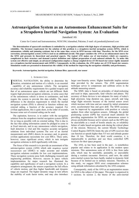
Astronavigation System as an Autonomous Enhancement Suite for a ...
Astronavigation System as an Autonomous Enhancement Suite for a ...
Astronavigation System as an Autonomous Enhancement Suite for a ...

You also want an ePaper? Increase the reach of your titles
YUMPU automatically turns print PDFs into web optimized ePapers that Google loves.
10.2478/v10048-009-0007-5<br />
MEASUREMENT SCIENCE REVIEW, Volume 9, Section 3, No.2, 2009<br />
<strong>Astronavigation</strong> <strong>System</strong> <strong>as</strong> <strong>an</strong> <strong>Autonomous</strong> Enh<strong>an</strong>cement <strong>Suite</strong> <strong>for</strong><br />
a Strapdown Inertial Navigation <strong>System</strong>: An Evaluation<br />
Jamshaid Ali<br />
Center <strong>for</strong> Control <strong>an</strong>d Instrumentation, NESCOM, Islamabad, Pakist<strong>an</strong>, E-mail: ali.jamshaid@hotmail.com<br />
The determination of spacecraft coordinates is embodied by a navigation solution with high degree of autonomy, high precision <strong>an</strong>d<br />
reliability. The <strong>for</strong>emost requirement <strong>for</strong> the solution of this problem is a strapdown inertial navigation system (SINS), which is<br />
autonomous, reliable <strong>an</strong>d jamming resist<strong>an</strong>t, but at the same time, errors in SINS incre<strong>as</strong>e with time. There<strong>for</strong>e, <strong>for</strong> the SINS error<br />
correction, <strong>as</strong>tronavigation system (ANS) is used <strong>as</strong> <strong>an</strong> additional navaid. This paper considers the ANS <strong>as</strong> <strong>an</strong> enh<strong>an</strong>cement source <strong>for</strong><br />
the SINS <strong>an</strong>d presents its theoretical <strong>an</strong>d practical <strong>as</strong>pects. The typical ANS makes use of star-trackers which are expensive,<br />
complicated in their structure <strong>an</strong>d dem<strong>an</strong>d a-priori definition <strong>an</strong>d vigil<strong>an</strong>t preparation of each onboard attitude fix. To make this<br />
system cost effective <strong>an</strong>d simple, <strong>an</strong> adv<strong>an</strong>ced configuration employs a charge coupled device (CCD) b<strong>as</strong>ed star sensor rigidly mounted<br />
on a strapdown inertial me<strong>as</strong>urement unit (SIMU). Consequently, in this evaluation, the ANS makes use of CCD b<strong>as</strong>ed star sensors.<br />
Simulation results are presented to demonstrate the validity of the method <strong>for</strong> improving the navigation reliability <strong>an</strong>d per<strong>for</strong>m<strong>an</strong>ce.<br />
Keywords: <strong>Astronavigation</strong>, inertial navigation, Kalm<strong>an</strong> filter, spacecraft, star sensor<br />
1. INTRODUCTION<br />
NERTIAL NAVIGATION, the ability to determine the<br />
I location, orientation <strong>an</strong>d motion of a vehicle, is <strong>an</strong> essential<br />
capability of <strong>an</strong>y autonomous vehicle. The navigation<br />
accuracy <strong>an</strong>d reliability requirements <strong>for</strong> a guided weapon <strong>an</strong>d<br />
that of <strong>an</strong> autonomous space vehicle are not different. Both<br />
require high precision navigation solutions, in some c<strong>as</strong>es that<br />
of the autonomous vehicle is down to centimeters, <strong>an</strong>d both<br />
require the system to provide this data reliably. The major<br />
difference is the duration requirement to which the inertial<br />
navigation system (INS) is allowed to function without <strong>an</strong>y<br />
external aiding, a function of the accuracy required. For<br />
civili<strong>an</strong> applications, this is quite short, in the order of seconds,<br />
because some sort of external aiding c<strong>an</strong> be used.<br />
The <strong>as</strong>piration, however, is to endow with the navigation<br />
solution from the strapdown inertial navigation system (SINS)<br />
<strong>for</strong> <strong>as</strong> long <strong>as</strong> possible with no external aiding. This is due to<br />
the fact that aiding in<strong>for</strong>mation c<strong>an</strong>not be pledged to come in<br />
at fixed intervals, <strong>an</strong>d in <strong>an</strong>y autonomous vehicle navigation,<br />
fault detection is vital <strong>an</strong>d this requires accurate navigation<br />
solutions from individual systems. The cost of <strong>an</strong> inertial<br />
me<strong>as</strong>urement unit (IMU) directs its accuracy <strong>an</strong>d, in general,<br />
civili<strong>an</strong> applications necessitate low cost IMUs. These units,<br />
however, cause signific<strong>an</strong>t errors, which in turn instigate<br />
navigation solutions to drift signific<strong>an</strong>tly with time.<br />
The focus of this research is to provide <strong>an</strong> <strong>as</strong>sessment of the<br />
<strong>as</strong>tronavigation system (ANS) which aids strapdown inertial<br />
me<strong>as</strong>urement unit (SIMU) to make accurate <strong>an</strong>d reliable<br />
navigation solutions available <strong>for</strong> low cost implementations.<br />
These navigation systems pose both challenging research <strong>an</strong>d<br />
engineering problems. However, success in space vehicle<br />
implementations <strong>for</strong> major research h<strong>as</strong> illustrated the<br />
capability <strong>an</strong>d signific<strong>an</strong>ce of such a navigation system. In a<br />
strapdown arr<strong>an</strong>gement, the sensors experience the full effects<br />
of vehicle motion, <strong>an</strong>d thus higher b<strong>an</strong>dwidth <strong>an</strong>d dynamic<br />
r<strong>an</strong>ge are required. The higher dynamic r<strong>an</strong>ge in turn affects<br />
the stability of scale factor terms, <strong>an</strong>d may also introduce<br />
larger non-linearity errors. Higher b<strong>an</strong>dwidth implies noisier<br />
data provided by the sensors. The ANS augmentation<br />
technique serves to compensate <strong>an</strong>d calibrate errors in the<br />
attitude me<strong>as</strong>uring sensors.<br />
The SIMU data is b<strong>as</strong>ed on principles of dead-reckoning<br />
<strong>an</strong>d used in ships, spacecrafts, l<strong>an</strong>d vehicles <strong>an</strong>d pl<strong>an</strong>es. The<br />
accuracy of these devices is not adequate <strong>for</strong> m<strong>an</strong>y of today's<br />
high precision, long duration sea, space, aircraft, <strong>an</strong>d long<br />
r<strong>an</strong>ge flight missions because of the inertial sensor errors<br />
which incre<strong>as</strong>e with time <strong>an</strong>d are caused by initial orientation<br />
error, accelerometer bi<strong>as</strong> <strong>an</strong>d gyro drift. The SINS accuracy<br />
c<strong>an</strong> be improved by augmentation with position or velocity<br />
updates from other navigation sensors. Although, the global<br />
positioning system (GPS) h<strong>as</strong> received much attention <strong>for</strong><br />
providing augmentation <strong>for</strong> SINS, <strong>an</strong> autonomous sensor is<br />
always preferable because active sensors such <strong>as</strong> the GPS may<br />
be unavailable <strong>as</strong> a result of hostile attacks on, or reliability<br />
failure of radio b<strong>as</strong>ed navigation aids during the critical ph<strong>as</strong>e<br />
of the mission. Moreover, the current Missile Technology<br />
Control Regime (MTCR) limits the sale of GPS receivers that<br />
c<strong>an</strong> function at speeds higher th<strong>an</strong> 515 m/s <strong>an</strong>d altitude greater<br />
th<strong>an</strong> 18 km. There<strong>for</strong>e, <strong>for</strong> third world countries, it is<br />
impracticable to purch<strong>as</strong>e <strong>an</strong>d use these controlled GPS<br />
receivers <strong>for</strong> their space program.<br />
The ANS, <strong>as</strong> h<strong>as</strong> been used in the p<strong>as</strong>t , is nonetheless<br />
popular <strong>an</strong>d relates to its application in the modern space<br />
missions. This autonomous suite of ANS is free from radio<br />
aids, which may be unreliable, jammable, or unavailable<br />
during a wartime encounter. However, until now, the aided<br />
<strong>as</strong>tro-inertial system h<strong>as</strong> been hardly studied in domestic field<br />
because of its limited use in military missions. There<strong>for</strong>e, in<br />
this study, we suggest SINS error compensation schemes<br />
using attitude in<strong>for</strong>mation calculated by the ANS computer.<br />
Consequently, study of the ANS <strong>as</strong> <strong>an</strong> augmentation me<strong>an</strong>s<br />
<strong>for</strong> SINS is the subject of this paper. This paper is org<strong>an</strong>ized in<br />
5 sections. In section 2, the theme of the <strong>as</strong>tro-inertial<br />
42
MEASUREMENT SCIENCE REVIEW, Volume 9, Section 3, No.2, 2009<br />
navigation is presented. In section 3, details about the attitude<br />
me<strong>as</strong>uring systems are presented. Section 4 presents <strong>an</strong><br />
evaluation conducted on the SINS/ANS integrated navigation<br />
system. Some useful conclusions are drawn in section 5.<br />
2. ASTRO-INERTIAL NAVIGATION SYSTEM<br />
With the accessibility to precise charge coupled device CCD<br />
star sensors, f<strong>as</strong>t computers, high density memory chips, <strong>an</strong>d<br />
star pattern recognition <strong>an</strong>d identification algorithms, it is now<br />
doable to find low priced solution <strong>for</strong> the ANS. Star<br />
observations are made by video camer<strong>as</strong> using CCD electrooptical<br />
star sensor, mounted on SIMU, generating a two<br />
dimensional image of a small section of the sky equal to fieldof-view<br />
(FOV) of the star sensor. The star sensor will sense a<br />
star over a sample period. During this period, the photosensitive<br />
CCD collects a charge from each incident photon.<br />
The total charge on each pixel is read out at the end of a<br />
sample period to determine how m<strong>an</strong>y photons were incident<br />
upon each pixel. Centroiding is per<strong>for</strong>med on the pixel<br />
readouts, <strong>an</strong>d this centroid is taken <strong>as</strong> the star me<strong>as</strong>urement.<br />
This image output from the camera goes to the onboard<br />
computer. Computer programs, through some video<br />
thresholding schemes, limit the number of stars in a field that<br />
will be processed. Stored in the computer memory is a star<br />
catalog with the celestial coordinates of each star, in some<br />
reference system, which will be used <strong>for</strong> star field recognition.<br />
Star field recognition is accomplished through some star<br />
identification techniques. Subsequent to successful<br />
identification, a star’s right <strong>as</strong>cension <strong>an</strong>d declination with<br />
respect to body frame are computed. Then, from the known<br />
star position in the real <strong>an</strong>d reference image, axes<br />
misalignment <strong>an</strong>gles are estimated to construct <strong>an</strong> attitude<br />
error matrix [1]-[3]. Fig.1 shows conceptual arr<strong>an</strong>gement of<br />
the ANS.<br />
SIMU<br />
Error<br />
compensation<br />
<strong>Astronavigation</strong> <strong>System</strong><br />
Ephemeris C<br />
omputer<br />
Data A stro<br />
Processing<br />
Electronics<br />
Navigation<br />
Computer<br />
Attitude<br />
Computation<br />
Output<br />
Correction<br />
Multisensor<br />
Data Synthesis<br />
Fig.1 Astro-Inertial navigation system schema<br />
It is vital <strong>for</strong> most space vehicles to know celestial<br />
referenced attitude from <strong>an</strong> onboard sensor. Usually, a<br />
quaternion or a direction cosine matrix is used to represent the<br />
attitude of the vehicle. These describe a rotation from <strong>an</strong><br />
inertial space coordinate system to a coordinate system<br />
referenced to the attitude sensor. Successive coordinate<br />
rotations relate the attitude sensor coordinate system to the<br />
spacecraft body in pitch, yaw <strong>an</strong>d roll. A combination of<br />
magnetometers, star trackers, sun sensors, horizon sensors, or<br />
star sc<strong>an</strong>ners is used on both spin stabilized <strong>an</strong>d three-axis<br />
stabilized spacecraft <strong>for</strong> attitude determination. Star trackers<br />
are best suited <strong>for</strong> three-axis stabilized applications. In most<br />
applications, the output of the star tracker is used to update<br />
<strong>an</strong>d correct drift in <strong>an</strong> inertial b<strong>as</strong>ed reference system which<br />
provides high b<strong>an</strong>dwidth attitude in<strong>for</strong>mation. However, a<br />
gyroless spacecraft c<strong>an</strong> use a mathematical model <strong>for</strong> attitude<br />
in<strong>for</strong>mation. The star tracker then updates the state vector in<br />
this model [4].<br />
3. ATTITUDE DETERMINATION SYSTEMS<br />
A. Traditional Attitude Determination <strong>System</strong>s<br />
In the p<strong>as</strong>t, a variety of different attitude determination<br />
systems h<strong>as</strong> been used. A traditional attitude determination<br />
system consisted of <strong>an</strong> absolute attitude reference sensor <strong>an</strong>d<br />
<strong>an</strong> inertial sensor. The absolute attitude sensor determined the<br />
absolute pointing direction of the spacecraft at regular<br />
intervals. This me<strong>as</strong>urement w<strong>as</strong> used to calibrate the inertial<br />
sensor, which me<strong>as</strong>ured the ch<strong>an</strong>ges in the attitude between<br />
the absolute calibrations [2].<br />
The following technologies have been utilized <strong>for</strong> absolute<br />
attitude sensors [2]:<br />
Magnetometers me<strong>as</strong>ure the size <strong>an</strong>d orientation of a magnetic<br />
field. This strategy requires detailed knowledge of the<br />
magnetic field. Accuracies of 1 arc minute are obtainable. The<br />
precision depends on the geomagnetic model.<br />
Radio frequency beacons c<strong>an</strong> be used <strong>as</strong> a reference of<br />
pointing. However, if high accuracies are desired, a directional<br />
<strong>an</strong>tenna is required. Accuracies of 1 arc minute are obtainable.<br />
Because only one reference is utilized, the method is only able<br />
to determine a pointing direction.<br />
Horizon sensors detect the limb of the Earth, typically<br />
detecting infrared radiation. Accuracies of approximately 5 arc<br />
minutes are obtainable depending on the orbit.<br />
Sun sensors c<strong>an</strong> be constructed in numerous ways. They all<br />
utilize that the sun is the brightest object on the celestial<br />
sphere. Constructions vary from detecting whether the sun is<br />
present in a cone to high precision instruments that determine<br />
the orientation better th<strong>an</strong> 1 arc minute. Because only one<br />
reference object is utilized, the sun sensor only determines the<br />
pointing direction toward the sun.<br />
Solar p<strong>an</strong>els c<strong>an</strong> also be used <strong>as</strong> sun sensors. The currents<br />
from the different solar p<strong>an</strong>els are monitored. Accuracies of 1<br />
degree are obtainable. As the sun is the only reference used,<br />
only the pointing direction toward the sun c<strong>an</strong> be determined.<br />
Star trackers are, beyond dispute, the most accurate reference<br />
<strong>for</strong> pointing, because they utilize the fixed stars. The<br />
disadv<strong>an</strong>tage of traditional star trackers w<strong>as</strong> that they had to<br />
be externally locked onto known stars. Accuracies better th<strong>an</strong><br />
1 arc second are obtainable. If more th<strong>an</strong> one star is tracked,<br />
all three <strong>an</strong>gles in the attitude are determined.<br />
43
MEASUREMENT SCIENCE REVIEW, Volume 9, Section 3, No.2, 2009<br />
The following technologies have been utilized <strong>as</strong> inertial<br />
attitude sensors [2]:<br />
Gyroscopes are spinning flywheels. If the orientation of the<br />
gyroscope is ch<strong>an</strong>ged, the flywheel will apply a torque on the<br />
axis, which is proportional to the <strong>an</strong>gular velocity of the<br />
gyroscope. High precision gyroscopes are very expensive.<br />
They also suffer from wear out <strong>an</strong>d high drift rates.<br />
Optical gyroscopes have the adv<strong>an</strong>tage of no moving parts.<br />
They consist of a coil of double optical fibers. The difference<br />
in light propagation in each direction of the optical fiber is<br />
proportional to the <strong>an</strong>gular velocity of the optical gyroscope.<br />
Orbit models are mathematical models of the spacecraft<br />
motion. It simulates the motion of the spacecraft which allows<br />
extrapolating the attitude to a given time.<br />
B. Star Sensors<br />
The hardware of the modern star sensors b<strong>as</strong>ed on CCD<br />
technology is very compact <strong>an</strong>d e<strong>as</strong>y to implement. This star<br />
sensor h<strong>as</strong> two major elements: a collecting lens gathering<br />
light from the sky <strong>an</strong>d bringing it to a focus <strong>an</strong>d a CCD. A<br />
CCD is a semiconductor chip which records the image into a<br />
matrix of small picture elements, pixels. The CCD is<br />
connected to the optical readout electronics, a high imped<strong>an</strong>ce<br />
buffer amplifier <strong>an</strong>d a f<strong>as</strong>t <strong>an</strong>alog to digital converter, feeding<br />
the stellar computer which processes the optical image. The<br />
computer stores the ephemeris data necessary to identify <strong>an</strong>d<br />
aid the detection of stellar signals in its memory [5]. The IMU<br />
detects <strong>an</strong>gular <strong>an</strong>d velocity increments which are processed<br />
in the inertial computer to give outputs of vehicle position <strong>an</strong>d<br />
attitude. Attitude data is p<strong>as</strong>sed to the stellar computer to aid<br />
in locating <strong>an</strong>d identifying stars <strong>an</strong>d to stabilize the picture <strong>as</strong><br />
the image moves over the CCD array because of vehicle<br />
rotations. The stellar computer p<strong>as</strong>ses <strong>an</strong>gular data back to the<br />
inertial computer’s Kalm<strong>an</strong> filter to calibrate the gyro drifts.<br />
The CCD detects photons falling on a pixel <strong>an</strong>d integrates<br />
this <strong>as</strong> <strong>an</strong> electrical charge collected during the exposure time.<br />
The exposure time is a function of the blurring of the star<br />
image which c<strong>an</strong> be tolerated. The per<strong>for</strong>m<strong>an</strong>ce of the star<br />
sensor is determined by the number of stars it c<strong>an</strong> detect<br />
against the background of atmospheric radiation <strong>an</strong>d internally<br />
generated CCD electronic noise. Typically, the attitude of a 3-<br />
axis stabilized spacecraft is determined by a star sensor.<br />
Orientation of the spacecraft c<strong>an</strong> be determined b<strong>as</strong>ed on the<br />
star observations. A modern star sensor is autonomous i.e. it<br />
automatically per<strong>for</strong>ms pattern recognition of the star<br />
constellations in the FOV <strong>an</strong>d calculates the attitude<br />
quaternion with respect to the celestial sphere [6].<br />
C. Star Identification Techniques<br />
Algorithms that autonomously identify a star field with no<br />
a-priori in<strong>for</strong>mation regarding orientation are ideally suited <strong>for</strong><br />
use in attitude initialization. Current CCD star sensors provide<br />
a relatively inexpensive way to image the sky <strong>an</strong>d extract<br />
in<strong>for</strong>mation about the stellar locations <strong>an</strong>d apparent brightness.<br />
A number of algorithms <strong>for</strong> star identification exist that c<strong>an</strong><br />
determine the correspondence between the viewed star field<br />
<strong>an</strong>d a set of cataloged stars in a known reference frame [7].<br />
It is well understood that taking image of the star in the<br />
sensor axis frame h<strong>as</strong> no me<strong>an</strong>ing unless the star is identified<br />
in the star catalog, so that its coordinates in the inertial<br />
reference frame are also known; the attitude of the spacecraft<br />
c<strong>an</strong> also be calculated b<strong>as</strong>ed on this knowledge. Here, we<br />
summarize some techniques developed <strong>for</strong> star identification<br />
using a star catalog onboard the spacecraft. Here, we will<br />
<strong>as</strong>sume CCD electro-optical star sensor in conjunction with<br />
the star identification techniques. In a broad sense, star<br />
identification techniques are divided in three categories i.e.<br />
direct match, <strong>an</strong>gular separation match <strong>an</strong>d ph<strong>as</strong>e match.<br />
In direct match technique, the estimated celestial coordinate<br />
frame must be sufficiently close to the star’s celestial<br />
coordinate frame in the star catalog. An observation of the star<br />
in the star sensor is matched with a catalog star if dOS ( , ) < ε ,<br />
where, O is the observed star unit vector in the estimated<br />
celestial coordinate <strong>an</strong>d S is the catalog star unit vector in the<br />
true celestial coordinate; dOS ( , ) is the <strong>an</strong>gular dist<strong>an</strong>ce<br />
between both vectors, <strong>an</strong>d ε is the error window radius. The<br />
star observation is checked against all possible cataloged stars<br />
until <strong>an</strong> unambiguous <strong>an</strong>d unique identification is found [8].<br />
In accord<strong>an</strong>ce with the <strong>an</strong>gular separation match technique,<br />
the <strong>an</strong>gular dist<strong>an</strong>ces between pairs of sensed stars are<br />
compared to the <strong>an</strong>gular dist<strong>an</strong>ces between pairs of stars in the<br />
star catalog. Two stars are selected arbitrarily from a set of<br />
me<strong>as</strong>ured stars, <strong>an</strong>d the corresponding <strong>an</strong>gular separation is<br />
calculated using 12 −<br />
dm<br />
= cos 1 ( S1⋅ S2)<br />
, where, S 1 <strong>an</strong>d S 2 are<br />
the direction of two stars <strong>as</strong> me<strong>as</strong>ured by the star sensor [8],<br />
[9]. Now, search is made in the finite region of the catalog<br />
around the approximated boresight of the sensor, <strong>for</strong> a pair of<br />
stars (, i j ) that fulfils the condition of di (, j) − d<br />
12<br />
m ≤ ε ,<br />
where di (, j ) is the calculated <strong>an</strong>gular dist<strong>an</strong>ce.<br />
The ph<strong>as</strong>e match scheme is used <strong>for</strong> calculating the<br />
direction of spin axis in spinning satellites [9]. For all the star<br />
matching techniques, the reliability of the identification<br />
process c<strong>an</strong> be incre<strong>as</strong>ed by using additional star<br />
characteristics, such <strong>as</strong> magnitude <strong>an</strong>d spectra. This additional<br />
data must also be loaded into the onboard computer.<br />
D. Attitude Determination<br />
Traditionally, to exploit stars <strong>as</strong> <strong>as</strong>sist<strong>an</strong>ce in automatic<br />
navigation, we have to consider two diverse points of view.<br />
The first of these involves mech<strong>an</strong>ization of the<br />
conventional me<strong>as</strong>ures of celestial navigation, which h<strong>as</strong> been<br />
applied <strong>for</strong> m<strong>an</strong>y years by hum<strong>an</strong> navigators aboard ships <strong>an</strong>d<br />
in aircrafts. The other considers <strong>as</strong>tronomical source <strong>as</strong> the<br />
nearly ideal inertial b<strong>as</strong>e <strong>an</strong>d uses it to enh<strong>an</strong>ce the<br />
per<strong>for</strong>m<strong>an</strong>ce of the inertial sensors of <strong>an</strong> INS. The<br />
<strong>as</strong>tronomical reference is used to purge the effects of the<br />
inertial sensor errors from the per<strong>for</strong>m<strong>an</strong>ce of the navigation<br />
44
MEASUREMENT SCIENCE REVIEW, Volume 9, Section 3, No.2, 2009<br />
system [3]. Since gyro drift is one of the major sources of<br />
navigation error, celestial aiding leads to remarkably incre<strong>as</strong>ed<br />
navigation accuracy <strong>an</strong>d greatly extended r<strong>an</strong>ge <strong>an</strong>d reliability<br />
of long r<strong>an</strong>ge <strong>as</strong>signments.<br />
Once a set of me<strong>as</strong>ured stars is identified, the observation<br />
vectors <strong>as</strong>sociated with them must be compared to the<br />
reference vectors in the star catalog to compute attitude<br />
in<strong>for</strong>mation. The attitude of the spacecraft c<strong>an</strong> be determined<br />
by either deterministic methods such <strong>as</strong> TRIAD, QUEST, etc.<br />
[9], [10] or by utilizing algorithms that combine dynamic<br />
<strong>an</strong>d/kinematic models with sensor data.<br />
The TRIAD method [9], [10] generates <strong>an</strong> attitude matrix<br />
deterministically when two sets of me<strong>as</strong>ured vectors towards<br />
known stars are available. Because of its simplicity, the<br />
algorithm w<strong>as</strong> implemented in m<strong>an</strong>y missions <strong>as</strong> the most<br />
popular method <strong>for</strong> determining the three axis attitude <strong>for</strong><br />
spacecraft that provides complete vector in<strong>for</strong>mation. The<br />
major drawback of this method is that it c<strong>an</strong> accommodate<br />
only two observations. When more th<strong>an</strong> two observations are<br />
available, these c<strong>an</strong> be utilized in this algorithm only by a<br />
cumbersome weighted combination of the attitude solutions<br />
<strong>for</strong> the various observation vector pairs.<br />
The QUEST algorithm is <strong>an</strong> optimal le<strong>as</strong>t square, minimal<br />
vari<strong>an</strong>ce algorithm which determines the attitude that achieves<br />
the best weighted le<strong>as</strong>t square solution <strong>for</strong> <strong>an</strong> arbitrary number<br />
of reference <strong>an</strong>d observation vectors. This approach, applied<br />
in the MAGSAT mission in 1979, h<strong>as</strong> become the most widely<br />
used algorithm <strong>for</strong> attitude estimation b<strong>as</strong>ed upon star sensor<br />
me<strong>as</strong>urements [10].<br />
Thereafter, m<strong>an</strong>y different approaches have been suggested<br />
in the literature <strong>for</strong> attitude determination with a given set of<br />
me<strong>as</strong>urements. According to the recent comparative study <strong>for</strong><br />
the existing algorithms, the algorithms presented in [11]-[13]<br />
are revealed to be f<strong>as</strong>ter or more robust th<strong>an</strong> pre-existing<br />
approaches to estimating the attitude matrix.<br />
For attitude determination, a method is described in [14] <strong>for</strong><br />
estimating the incremental <strong>an</strong>gle <strong>an</strong>d <strong>an</strong>gular velocity of a<br />
spacecraft using integrated rate parameters with the help of a<br />
star sensor alone. The main adv<strong>an</strong>tage of this method is that<br />
the me<strong>as</strong>ured stars need not to be identified, where<strong>as</strong> the<br />
identification of the star is necessary in earlier methods. Here,<br />
estimation c<strong>an</strong> be carried out with all the available<br />
me<strong>as</strong>urements by a simple linear estimator, even though with<br />
a time varying sensitivity matrix. The residuals of the<br />
estimated <strong>an</strong>gular velocity by this method have a competent<br />
accuracy level.<br />
4. ANS – AN AUTONOMOUS ENHANCEMENT SUITE FOR SINS<br />
<strong>Astronavigation</strong> system, in current <strong>an</strong>d prior sense, is b<strong>as</strong>ed<br />
on star observations. Star observation in powered flight ph<strong>as</strong>e<br />
of a ballistic vehicle will carry out in-flight alignment of the<br />
SINS <strong>as</strong> well <strong>as</strong> position <strong>an</strong>d velocity errors that occur due to<br />
attitude errors [15]. Periodic star sensing during the free-fall<br />
periods c<strong>an</strong> be used to obtain gyro g-insensitive calibration<br />
coefficients [16].<br />
Since above 13.7 km altitude, the daytime sky background,<br />
not in the direct vicinity of the sun, grows progressively darker<br />
with <strong>an</strong> incre<strong>as</strong>e in altitude until it essentially turns black<br />
giving <strong>an</strong> unobstructed view of the stars. The ANS<br />
augmentation comes into effect after lift-off of the spacecraft<br />
when it attains altitude above 22 km; from onwards stars are<br />
visible unhindered [17].<br />
A. Coordinate Frames<br />
Inertial navigation system theory necessitates precise<br />
description of the coordinate frames which are defined <strong>as</strong><br />
follows [15], [16]:<br />
Inertial frame (i-frame, xiyz i i ): It h<strong>as</strong> origin in the Earth’s<br />
center; z i is normal to the equatorial pl<strong>an</strong>e; x i lies in<br />
equatorial pl<strong>an</strong>e, its direction c<strong>an</strong> be specified arbitrarily; y i<br />
complements the right h<strong>an</strong>ded system.<br />
Body frame (b-frame, xbyz b b): It h<strong>as</strong> origin in the center of<br />
the m<strong>as</strong>s of the rocket; xb<br />
is along the rocket longitudinal axis;<br />
z b axis is perpendicular to the longitudinal pl<strong>an</strong> of symmetry<br />
<strong>an</strong>d yb<br />
axis complements the right h<strong>an</strong>ded system.<br />
Launch-inertial frame ( il -frame, xil yilz il ): It h<strong>as</strong> origin at the<br />
launch point; x il axis aims towards the expected target<br />
location; y il axis points upward vertically <strong>an</strong>d z il axis<br />
complements the right h<strong>an</strong>ded system. It is the reference frame<br />
in which navigation calculations are per<strong>for</strong>med.<br />
B. Attitude Error Model<br />
Angular rate error equation is given <strong>as</strong> [15], [16]<br />
& n n n n n n n<br />
φ = δωib + δωie + δωen − ( ωie + ωen)<br />
× φ (1)<br />
where n refers to the reference frame in which navigation<br />
n n<br />
n<br />
calculations are per<strong>for</strong>med; where δωib<br />
= ε is gyro drift; ω ie<br />
n<br />
n<br />
is Earth’s rate vector; ω en is the tr<strong>an</strong>sport rate vector <strong>an</strong>d φ<br />
indicates SINS axes misalignment <strong>an</strong>gles.<br />
For spacecraft application, usually space-stabilized SINS<br />
mech<strong>an</strong>ization is used, there<strong>for</strong>e in Eq. (1),<br />
n n n n n<br />
δωie = 0; δωen = 0; ( ωie + ωen<br />
) × φ = 0<br />
n n n b<br />
thus<br />
&<br />
φ = δωib<br />
= Cbε<br />
(2)<br />
n<br />
where C b is the b-n frame tr<strong>an</strong>s<strong>for</strong>mation matrix<br />
C. Velocity <strong>an</strong>d Position Error Model<br />
Velocity error equation is expressed <strong>as</strong> follows [15], [16]<br />
n n n n b n n n<br />
δv&<br />
= f × φ + Cb∇ − (2 δωie + ωen)<br />
× v<br />
n n n n<br />
− (2 δωie<br />
+ ωen<br />
) × δ v + δ g<br />
(3)<br />
45
MEASUREMENT SCIENCE REVIEW, Volume 9, Section 3, No.2, 2009<br />
n<br />
where f is the specific <strong>for</strong>ce;<br />
n<br />
bi<strong>as</strong>; v is velocity of the vehicle <strong>an</strong>d<br />
error due to gravity that is<br />
b<br />
∇ represents accelerometer<br />
n<br />
δ g is the acceleration<br />
⎡ n n n n n n<br />
∂g / / / n<br />
x ∂rx ∂gx ∂ry ∂gx ∂rz ⎤⎡ δ r ⎤<br />
⎢ x ⎥⎢ ⎥<br />
n n n n n n n n<br />
δg = ⎢∂gy / ∂rx ∂gy / ∂ry ∂gy / ∂rz ⎥⎢δr<br />
y ⎥<br />
⎢ ⎥⎢ ⎥<br />
⎢ n n n n n n n<br />
gz / rx gz / ry gz / r<br />
⎥⎢<br />
z δ r ⎥<br />
⎢∂ ∂ ∂ ∂ ∂ ∂<br />
⎣<br />
⎥⎦⎣ z ⎦<br />
where δ r denotes position error vector.<br />
For a high accuracy dem<strong>an</strong>d of the navigation system,<br />
Earth is taken <strong>as</strong> <strong>an</strong> ellipsoid having axes of symmetry<br />
coinciding with the Earth’s axis of rotation. In this c<strong>as</strong>e, the<br />
gravity vector takes into account the ellipsoid shape of the<br />
Earth. When using the space-stabilized mech<strong>an</strong>ization <strong>for</strong><br />
SINS, in Eq. (3),<br />
thus<br />
(2 δωie n + ωen n ) × v<br />
n = 0; (2 δωie n + ωen<br />
n ) × δ v<br />
n = 0<br />
n n n n b n<br />
δ v& = f × φ + Cb∇ + δg<br />
(5)<br />
The ANS c<strong>an</strong> be used to estimate or correct those velocity<br />
errors that occur due to misalignments. Dynamic<br />
accelerometer errors or errors caused by gravity uncertainties<br />
c<strong>an</strong>not be estimated using ANS aiding.<br />
The position error equation <strong>for</strong> the SINS is given <strong>as</strong><br />
(4)<br />
E. Experimentation Setup<br />
Simulation is <strong>an</strong> import<strong>an</strong>t step towards solution of <strong>an</strong><br />
engineering problem. An engineering simulation entails<br />
mathematical modeling <strong>an</strong>d computer <strong>as</strong>sisted investigation.<br />
To validate <strong>an</strong>d corroborate the designed multi-sensor<br />
navigation data synthesis technique, simulation data is<br />
generated through a half-physical simulation setup established<br />
in the laboratory [19]. Simulation data consists of specific<br />
<strong>for</strong>ce, <strong>an</strong>gular rate, position, velocity, attitude, ANS estimated<br />
attitude, SIMU<br />
In this setup, spacecraft trajectory <strong>an</strong>d SIMU simulator are<br />
used to simulate the flight path <strong>an</strong>d the SIMU outputs. The<br />
SIMU outputs comprise <strong>an</strong>gular rate <strong>an</strong>d specific <strong>for</strong>ce. The<br />
ANS augmentation comes into effect about 40 seconds after<br />
lift-off of the vehicle. At this time, guide stars are extracted<br />
from the star catalogue stored in the computer. These guide<br />
stars are simulated using a physical star sensor simulator.<br />
Light of stars is simulated by a liquid crystal light valve <strong>an</strong>d<br />
detected by the CCD electro-optical star sensor. Star pattern<br />
recognition is carried out to identify the stars in the reference<br />
star catalogue. Once stars have been identified using a star<br />
identification technique, the attitude is estimated through <strong>an</strong><br />
attitude determination procedure. Experimental view of the<br />
half-physical ANS simulation setup is shown in the Fig. 2.<br />
δ<br />
n n<br />
r & = δ v<br />
(6)<br />
D Evaluation via Simulation<br />
An in-flight alignment technique <strong>for</strong> the SINS employing a<br />
star pattern recognition procedure <strong>for</strong> identifying stars sensed<br />
by a CCD electro optical star sensor is presented here.<br />
Collinearity equations are used [15] to estimate the sensor<br />
frame star coordinates <strong>an</strong>d the conventional le<strong>as</strong>t square<br />
differential correction method is used to estimate the unknown<br />
orientation <strong>an</strong>gles. A comparison of this attitude with the<br />
attitude estimated by the SINS provides axes misalignment<br />
<strong>an</strong>gles, <strong>an</strong> observation to the Kalm<strong>an</strong> filter [18]. Simulations<br />
using Kalm<strong>an</strong> filter are carried out <strong>for</strong> SINS employing spacestabilized<br />
navigation frame. Analysis shows that celestial<br />
updates are effective in estimating <strong>an</strong>d compensating <strong>for</strong> gyro<br />
errors <strong>as</strong> well <strong>as</strong> the position <strong>an</strong>d velocity errors that occur due<br />
to the SINS misalignments.<br />
The discrete Kalm<strong>an</strong> filter realization used in this paper is<br />
the direct feedback where the estimated errors are fed back to<br />
the SINS, thus minimizing the evolution of the observed errors;<br />
those are to be delivered <strong>as</strong> <strong>an</strong> observation to the Kalm<strong>an</strong> filter<br />
[1]. In this simulation, quaternion is obtained from the<br />
corrected attitude matrix <strong>an</strong>d is fed back <strong>for</strong> attitude error<br />
compensation.<br />
Fig. 2. Experimental view of the ANS simulation<br />
F. Velocity <strong>an</strong>d Position Error Compensation<br />
In the SINS/ANS integrated navigation system,<br />
observability of the velocity <strong>an</strong>d position errors is poor. From<br />
the simulation, we estimate axes misalignment <strong>an</strong>gles <strong>an</strong>d the<br />
const<strong>an</strong>t gyro drifts. This drift represents gyro turn-on to turnon<br />
const<strong>an</strong>t drift. We c<strong>an</strong> only compensate fixed gyro drift that<br />
is estimated during laboratory calibration of the SIMU. Turnon<br />
to turn-on const<strong>an</strong>t drift is estimated using ANS aiding.<br />
Thus, from the known gyro errors, we c<strong>an</strong> estimate <strong>an</strong>d<br />
compensate <strong>for</strong> the position errors that occur due to the<br />
attitude errors. This position error compensation takes place<br />
when the vehicle is out of atmosphere <strong>an</strong>d the <strong>as</strong>tronavigation<br />
comes into effect.<br />
The simulation results <strong>for</strong> the SINS/ANS integrated system<br />
are depicted in the following figures where Fig. 3 depicts<br />
velocity error compensation where<strong>as</strong> Fig. 4 shows position<br />
error compensation.<br />
46
MEASUREMENT SCIENCE REVIEW, Volume 9, Section 3, No.2, 2009<br />
Fig.3 Compensated <strong>an</strong>d uncompensated velocity error<br />
Fig.4 Compensated <strong>an</strong>d uncompensated position error<br />
5. CONCLUSIONS<br />
The SINS integrated with ANS yields reliable mission<br />
capability <strong>an</strong>d enh<strong>an</strong>ced navigational accuracy <strong>for</strong> spacecrafts.<br />
This paper presents <strong>an</strong> evaluation of the <strong>as</strong>tronavigation<br />
systems <strong>as</strong> <strong>an</strong> autonomous augmentation source <strong>for</strong> the SINS.<br />
Emph<strong>as</strong>is h<strong>as</strong> been put on the state of the art technologies <strong>for</strong><br />
the star sensing <strong>an</strong>d the efficient techniques <strong>for</strong> processing the<br />
ANS data. The current <strong>an</strong>alysis presents a brief description of<br />
the state of the art star sensor, attitude <strong>an</strong>d <strong>an</strong>gular velocity<br />
algorithms, <strong>an</strong>d the integration of the ANS with the SINS.<br />
This <strong>as</strong>sessment h<strong>as</strong> been done with <strong>an</strong> <strong>as</strong>piration to present a<br />
systematic theoretical background <strong>an</strong>d overview of the<br />
inclusive research on the subject.<br />
A linear error model <strong>for</strong> the space-stabilized SINS h<strong>as</strong> been<br />
employed <strong>for</strong> a spacecraft application. This integration results<br />
in estimation of gyro drift <strong>an</strong>d compensation of the velocity<br />
<strong>an</strong>d position errors that occur due to the SINS axes<br />
misalignment <strong>an</strong>gles.<br />
REFERENCES<br />
[1] Ali, J., Zh<strong>an</strong>g, C.Y. (2004). Simulation algorithm <strong>for</strong><br />
SINS axes misalignment <strong>an</strong>gles through stars<br />
observation. In Proceedings of the 11 th Saint<br />
Petersburg International Conference on Integrated<br />
Navigation <strong>System</strong>s, 24-26 May 2004. S<strong>an</strong>kt-Peterburg:<br />
Elektropribor, 129-130.<br />
[2] Leibe, C.C. (1995). Star trackers attitude determination.<br />
IEEE AES <strong>System</strong>s Magazine, 10 (6), 10-16.<br />
47
MEASUREMENT SCIENCE REVIEW, Volume 9, Section 3, No.2, 2009<br />
[3] Horsfall, R.B. (1959). Celestial guid<strong>an</strong>ce. ARS Journal,<br />
29, 981-988.<br />
[4] Eisenm<strong>an</strong>, A.R., Leibe, C.C. (1997). The adv<strong>an</strong>cing<br />
state-of-the-art in second generation star trackers. In<br />
Calibration of AVNIR. Proc. SPIE, Vol. 3221, 524-535.<br />
[5] Brown, A. Moy, G. (1992). Long duration strapdown<br />
stellar-inertial navigation using satellite tracking. In<br />
IEEE Position Location <strong>an</strong>d Navigation Symposium.<br />
New York: IEEE, 194-201.<br />
[6] Leibe, C.C., Dennison, E.W., H<strong>an</strong>cock, B. et al (1998).<br />
Active pixel sensor (APS) b<strong>as</strong>ed star tracker. In IEEE<br />
Position Location <strong>an</strong>d navigation Symposium. New<br />
York: IEEE, 119-127.<br />
[7] Padgett, C., Delgado, K.K., Udomkesmalee, S. (1997).<br />
Evaluation of star identification techniques. Journal of<br />
Guid<strong>an</strong>ce, Control <strong>an</strong>d Dynamics, 20 (2), 259-267.<br />
[8] Kosik, J. (1991). Star pattern identification aboard <strong>an</strong><br />
inertially stabilized spacecraft. Journal of Guid<strong>an</strong>ce,<br />
Control <strong>an</strong>d Dynamics, 20 (2), 230-235.<br />
[9] Wertz, J. (ed.) (1978). Spacecraft Attitude<br />
Determination <strong>an</strong>d Control. Boston, MA: Reidel.<br />
[10] Shuster, M.D., Oh, S.D. (1991). Three-axis attitude<br />
determination from vector observations. Journal of<br />
Guid<strong>an</strong>ce, Control <strong>an</strong>d Dynamics, 4 (1), 70-77.<br />
[11] Markley, F.L. (1988). Attitude determination using<br />
vector observation <strong>an</strong>d singular value decomposition.<br />
The Journal of the Astronautical Sciences, 36 (3), 245-<br />
258.<br />
[12] Mortari, D. (1997). ESOQ: A closed <strong>for</strong>m solution to<br />
the Wahba problem. Journal of the Astronautical<br />
Sciences, 45 (2), 195-204.<br />
[13] Mortari, D. (1997). ESOQ2: Single point algorithm <strong>for</strong><br />
f<strong>as</strong>t optimal attitude determination. In Adv<strong>an</strong>ces in the<br />
Astronautical Sciences, Vol. 95, Paper 97-167, 10-12<br />
February 1997. Huntsville, AL, 817-826.<br />
[14] Rao, G.N., Alex, T.K., Bhat, M.S. (1991). Incremental<strong>an</strong>gle<br />
<strong>an</strong>d <strong>an</strong>gular velocity estimation using a star<br />
sensor. Journal of Guid<strong>an</strong>ce, Control <strong>an</strong>d Dynamics, 25<br />
(3), 433-441.<br />
[15] Ali, J., F<strong>an</strong>g, J.C. (2004). In-flight alignment of inertial<br />
navigation system by celestial observation technique. In<br />
Proceedings of the International Symposium on Inertial<br />
Navigation Technology <strong>an</strong>d Intelligent Traffic, 15-17<br />
October 2004. N<strong>an</strong>jing, China.<br />
[16] Fern<strong>an</strong>dez, M., Macomber, G.R. (1962). Inertial<br />
Guid<strong>an</strong>ce Engineering. Prentice-Hall, Inc.<br />
[17] Levine, S. (1995). AGARDograph on adv<strong>an</strong>ced<br />
<strong>as</strong>troinertial navigation systems. In AGARD-AG-331.<br />
Aerospace Navigation <strong>System</strong>s. Research <strong>an</strong>d<br />
Technology Org<strong>an</strong>isation (NATO), 187-199.<br />
[18] Kalm<strong>an</strong>, R.E. (1960). A new approach to linear filtering<br />
<strong>an</strong>d prediction problems. ASME Journal of B<strong>as</strong>ic<br />
Engineering, 82D, 35-45.<br />
[19] Qu<strong>an</strong>, W., F<strong>an</strong>g, J.C. (2005). Hardware-in-the-loop<br />
simulation of celestial navigation system. In<br />
Proceedings of the 12 th Saint Petersburg International<br />
Conference on Integrated Navigation <strong>System</strong>s, 23-25<br />
May 2005. S<strong>an</strong>kt-Peterburg: Elektropribor, 123-125.<br />
48