Synchronous Motors
Synchronous Motors
Synchronous Motors

Create successful ePaper yourself
Turn your PDF publications into a flip-book with our unique Google optimized e-Paper software.
11.8 Motor Phasor Diagram<br />
Consider an under-excited ^tar-connected synchronous motor (E b < V) supplied<br />
with fixed excitation i.e., back e.m.f. E b is constant-<br />
Let V = supply voltage/phase<br />
E b = back e.m.f./phase<br />
Z s = synchronous impedance/phase<br />
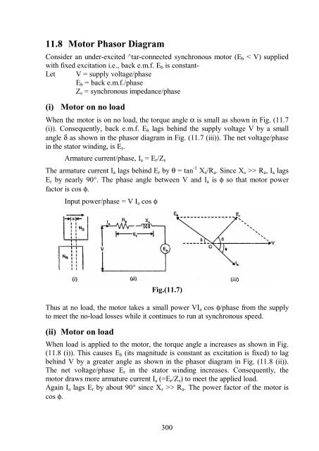
(i) Motor on no load<br />
When the motor is on no load, the torque angle α is small as shown in Fig. (11.7<br />
(i)). Consequently, back e.m.f. E b lags behind the supply voltage V by a small<br />
angle δ as shown in the phasor diagram in Fig. (11.7 (iii)). The net voltage/phase<br />
in the stator winding, is E r .<br />
Armature current/phase, I a = E r /Z s<br />
The armature current I a lags behind E r by θ = tan -1 X s /R a . Since X s >> R a , I a lags<br />
E r by nearly 90°. The phase angle between V and I a is φ so that motor power<br />
factor is cos φ.<br />
Input power/phase = V I a cos φ<br />
Fig.(11.7)<br />
Thus at no load, the motor takes a small power VI a cos φ/phase from the supply<br />
to meet the no-load losses while it continues to run at synchronous speed.<br />
(ii) Motor on load<br />
When load is applied to the motor, the torque angle a increases as shown in Fig.<br />
(11.8 (i)). This causes E b (its magnitude is constant as excitation is fixed) to lag<br />
behind V by a greater angle as shown in the phasor diagram in Fig. (11.8 (ii)).<br />
The net voltage/phase E r in the stator winding increases. Consequently, the<br />
motor draws more armature current I a (=E r /Z s ) to meet the applied load.<br />
Again I a lags E r by about 90° since X s >> R a . The power factor of the motor is<br />
cos φ.<br />
300