Synchronous Motors
Synchronous Motors
Synchronous Motors

Create successful ePaper yourself
Turn your PDF publications into a flip-book with our unique Google optimized e-Paper software.
Chapter (11)<br />
<strong>Synchronous</strong> <strong>Motors</strong><br />
Introduction<br />
It may be recalled that a d.c. generator can be run as a d.c. motor. In like<br />
manner, an alternator may operate as a motor by connecting its armature<br />
winding to a 3-phase supply. It is then called a synchronous motor. As the name<br />
implies, a synchronous motor runs at synchronous speed (N s = 120f/P) i.e., in<br />
synchronism with the revolving field produced by the 3-phase supply. The speed<br />
of rotation is, therefore, tied to the frequency of the source. Since the frequency<br />
is fixed, the motor speed stays constant irrespective of the load or voltage of 3-<br />
phase supply. However, synchronous motors are not used so much because they<br />
run at constant speed (i.e., synchronous speed) but because they possess other<br />
unique electrical properties. In this chapter, we shall discuss the working and<br />
characteristics of synchronous motors.<br />
11.1 Construction<br />
A synchronous motor is a machine that operates at synchronous speed and<br />
converts electrical energy into mechanical energy. It is fundamentally an<br />
alternator operated as a motor. Like an alternator, a synchronous motor has the<br />
following two parts:<br />
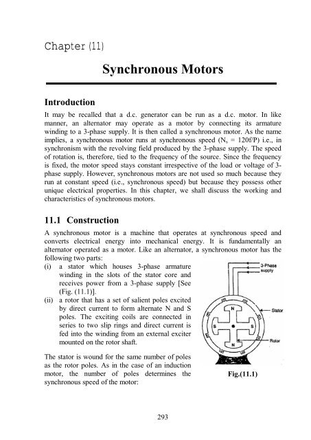
(i)<br />
a stator which houses 3-phase armature<br />
winding in the slots of the stator core and<br />
receives power from a 3-phase supply [See<br />
(Fig. (11.1)].<br />
(ii) a rotor that has a set of salient poles excited<br />
by direct current to form alternate N and S<br />
poles. The exciting coils are connected in<br />
series to two slip rings and direct current is<br />
fed into the winding from an external exciter<br />
mounted on the rotor shaft.<br />
The stator is wound for the same number of poles<br />
as the rotor poles. As in the case of an induction<br />
motor, the number of poles determines the<br />
synchronous speed of the motor:<br />
Fig.(11.1)<br />
293
where<br />
<strong>Synchronous</strong> speed,<br />
120f<br />
N s =<br />
P<br />
f = frequency of supply in Hz<br />
P = number of poles<br />
An important drawback of a synchronous motor is that it is not self-starting and<br />
auxiliary means have to be used for starting it.<br />
11.2 Some Facts about <strong>Synchronous</strong> Motor<br />
Some salient features of a synchronous motor are:<br />
(i) A synchronous motor runs at synchronous speed or not at all. Its speed is<br />
constant (synchronous speed) at all loads. The only way to change its speed<br />
is to alter the supply frequency (N s = 120 f/P).<br />
(ii) The outstanding characteristic of a synchronous motor is that it can be<br />
made to operate over a wide range of power factors (lagging, unity or<br />
leading) by adjustment of its field excitation. Therefore, a synchronous<br />
motor can be made to carry the mechanical load at constant speed and at<br />
the same time improve the power factor of the system.<br />
(iii) <strong>Synchronous</strong> motors are generally of the salient pole type.<br />
(iv) A synchronous motor is not self-starting and an auxiliary means has to be<br />
used for starting it. We use either induction motor principle or a separate<br />
starting motor for this purpose. If the latter method is used, the machine<br />
must be run up to synchronous speed and synchronized as an alternator.<br />
11.3 Operating Principle<br />
The fact that a synchronous motor has no starting torque can be easily explained.<br />
(i) Consider a 3-phase synchronous motor having two rotor poles N R and S R .<br />
Then the stator will also be wound for two poles N S and S S . The motor has<br />
direct voltage applied to the rotor winding and a 3-phase voltage applied to<br />
the stator winding. The stator winding produces a rotating field which<br />
revolves round the stator at synchronous speed N s (= 120 f/P). The direct (or<br />
zero frequency) current sets up a two-pole field which is stationary so long<br />
as the rotor is not turning. Thus, we have a situation in which there exists a<br />
pair of revolving armature poles (i.e., N S − S S ) and a pair of stationary rotor<br />
poles (i.e., N R − S R ).<br />
(ii) Suppose at any instant, the stator poles are at positions A and B as shown<br />
in Fig. (11.2 (i)). It is clear that poles N S and N R repel each other and so do<br />
the poles S S and S R . Therefore, the rotor tends to move in the anticlockwise<br />
direction. After a period of half-cycle (or ½ f = 1/100 second),<br />
the polarities of the stator poles are reversed but the polarities of the rotor<br />
poles remain the same as shown in Fig. (11.2 (ii)). Now S S and N R attract<br />
294
each other and so do N S and S R . Therefore, the rotor tends to move in the<br />
clockwise direction. Since the stator poles change their polarities rapidly,<br />
they tend to pull the rotor first in one direction and then after a period of<br />
half-cycle in the other. Due to high inertia of the rotor, the motor fails to<br />
start.<br />
Fig.(10.2)<br />
Hence, a synchronous motor has no self-starting torque i.e., a synchronous<br />
motor cannot start by itself.<br />
How to get continuous unidirectional torque? If the rotor poles are rotated by<br />
some external means at such a speed that they interchange their positions along<br />
with the stator poles, then the rotor will experience a continuous unidirectional<br />
torque. This can be understood from the following discussion:<br />
(i) Suppose the stator field is rotating in the clockwise direction and the rotor<br />
is also rotated clockwise by some external means at such a speed that the<br />
rotor poles interchange their positions along with the stator poles.<br />
(ii) Suppose at any instant the stator and rotor poles are in the position shown<br />
in Fig. (11.3 (i)). It is clear that torque on the rotor will be clockwise. After<br />
a period of half-cycle, the stator poles reverse their polarities and at the<br />
same time rotor poles also interchange their positions as shown in Fig.<br />
(11.3 (ii)). The result is that again the torque on the rotor is clockwise.<br />
Hence a continuous unidirectional torque acts on the rotor and moves it in<br />
the clockwise direction. Under this condition, poles on the rotor always<br />
face poles of opposite polarity on the stator and a strong magnetic<br />
attraction is set up between them. This mutual attraction locks the rotor and<br />
stator together and the rotor is virtually pulled into step with the speed of<br />
revolving flux (i.e., synchronous speed).<br />
(iii) If now the external prime mover driving the rotor is removed, the rotor will<br />
continue to rotate at synchronous speed in the clockwise direction because<br />
the rotor poles are magnetically locked up with the stator poles. It is due to<br />
295
this magnetic interlocking between stator and rotor poles that a<br />
synchronous motor runs at the speed of revolving flux i.e., synchronous<br />
speed.<br />
Fig.(11.3)<br />
11.4 Making <strong>Synchronous</strong> Motor Self-Starting<br />
A synchronous motor cannot start by itself. In order<br />
to make the motor self-starting, a squirrel cage<br />
winding (also called damper winding) is provided<br />
on the rotor. The damper winding consists of copper<br />
bars embedded in the pole faces of the salient poles<br />
of the rotor as shown in Fig. (11.4). The bars are<br />
short-circuited at the ends to form in effect a partial<br />
squirrel cage winding. The damper winding serves Fig.(11.4)<br />
to start the motor.<br />
(i) To start with, 3-phase supply is given to the stator winding while the rotor<br />
field winding is left unenergized. The rotating stator field induces currents<br />
in the damper or squirrel cage winding and the motor starts as an induction<br />
motor.<br />
(ii) As the motor approaches the synchronous speed, the rotor is excited with<br />
direct current. Now the resulting poles on the rotor face poles of opposite<br />
polarity on the stator and a strong magnetic attraction is set up between<br />
them. The rotor poles lock in with the poles of rotating flux. Consequently,<br />
the rotor revolves at the same speed as the stator field i.e., at synchronous<br />
speed.<br />
(iii) Because the bars of squirrel cage portion of the rotor now rotate at the same<br />
speed as the rotating stator field, these bars do not cut any flux and,<br />
therefore, have no induced currents in them. Hence squirrel cage portion of<br />
the rotor is, in effect, removed from the operation of the motor.<br />
296
It may be emphasized here that due to magnetic interlocking between the stator<br />
and rotor poles, a synchronous motor can only run at synchronous speed. At any<br />
other speed, this magnetic interlocking (i.e., rotor poles facing opposite polarity<br />
stator poles) ceases and the average torque becomes zero. Consequently, the<br />
motor comes to a halt with a severe disturbance on the line.<br />
Note: It is important to excite the rotor with direct current at the right moment.<br />
For example, if the d.c. excitation is applied when N-pole of the stator faces N-<br />
pole of the rotor, the resulting magnetic repulsion will produce a violent<br />
mechanical shock. The motor will immediately slow down and the circuit<br />
breakers will trip. In practice, starters for synchronous motors arc designed to<br />
detect the precise moment when excitation should be applied.<br />
11.5 Equivalent Circuit<br />
Unlike the induction motor, the synchronous motor is connected to two<br />
electrical systems; a d.c. source at the rotor terminals and an a.c. system at the<br />
stator terminals.<br />
1. Under normal conditions of synchronous motor operation, no voltage is<br />
induced in the rotor by the stator field because the rotor winding is rotating<br />
at the same speed as the stator field. Only the impressed direct current is<br />
present in the rotor winding and ohmic resistance of this winding is the<br />
only opposition to it as shown in Fig. (11.5 (i)).<br />
2. In the stator winding, two effects are to be considered, the effect of stator<br />
field on the stator winding and the effect of the rotor field cutting the stator<br />
conductors at synchronous speed.<br />
Fig.(11.5)<br />
(i) The effect of stator field on the stator (or armature) conductors is<br />
accounted for by including an inductive reactance in the armature<br />
winding. This is called synchronous reactance X s . A resistance R a must<br />
be considered to be in series with this reactance to account for the copper<br />
losses in the stator or armature winding as shown in Fig. (11.5 (i)). This<br />
297
esistance combines with synchronous reactance and gives the<br />
synchronous impedance of the machine.<br />
(ii) The second effect is that a voltage is generated in the stator winding by<br />
the synchronously-revolving field of the rotor as shown in Fig. (11.5 (i)).<br />
This generated e.m.f. E B is known as back e.m.f. and opposes the stator<br />
voltage V. The magnitude of E b depends upon rotor speed and rotor flux<br />
φ per pole. Since rotor speed is constant; the value of E b depends upon<br />
the rotor flux per pole i.e. exciting rotor current I f .<br />
Fig. (11.5 (i)) shows the schematic diagram for one phase of a star-connected<br />
synchronous motor while Fig. (11.5 (ii)) shows its equivalent circuit. Referring<br />
to the equivalent circuit in Fig. (11.5 (ii)).<br />
Net voltage/phase in stator winding is<br />
E r = V − E b<br />
Armature current/phase,<br />
E<br />
I a =<br />
Z<br />
r<br />
s<br />
phasor difference<br />
where<br />
s<br />
2<br />
a<br />
Z = R + X<br />
2<br />
s<br />
This equivalent circuit helps considerably in understanding the operation of a<br />
synchronous motor.<br />
A synchronous motor is said to be normally excited if the field excitation is such<br />
that E b = V. If the field excitation is such that E b < V, the motor is said to be<br />
under-excited. The motor is said to be over-excited if the field excitation is such<br />
that E b > V. As we shall see, for both normal and under excitation, the motor has<br />
lagging power factor. However, for over-excitation, the motor has leading power<br />
factor.<br />
Note: In a synchronous motor, the value of X s is 10 to 100 times greater than R a .<br />
Consequently, we can neglect R a unless we are interested in efficiency or<br />
heating effects.<br />
11.6 Motor on Load<br />
In d.c. motors and induction motors, an addition of load causes the motor speed<br />
to decrease. The decrease in speed reduces the counter e.m.f. enough so that<br />
additional current is drawn from the source to carry the increased load at a<br />
reduced speed. This action cannot take place in a synchronous motor because it<br />
runs at a constant speed (i.e., synchronous speed) at all loads.<br />
What happens when we apply mechanical load to a synchronous motor? The<br />
rotor poles fall slightly behind the stator poles while continuing to run at<br />
298
synchronous speed. The angular displacement between stator and rotor poles<br />
(called torque angle α) causes the phase of back e.m.f. E b to change w.r.t. supply<br />
voltage V. This increases the net e.m.f. E r in the stator winding. Consequently,<br />
stator current I a ( = E r /Z s ) increases to carry the load.<br />
Fig.(11.6)<br />
The following points may be noted in synchronous motor operation:<br />
(i) A synchronous motor runs at synchronous speed at all loads. It meets the<br />
increased load not by a decrease in speed but by the relative shift between<br />
stator and rotor poles i.e., by the adjustment of torque angle α.<br />
(ii) If the load on the motor increases, the torque angle a also increases (i.e.,<br />
rotor poles lag behind the stator poles by a greater angle) but the motor<br />
continues to run at synchronous speed. The increase in torque angle α<br />
causes a greater phase shift of back e.m.f. E b w.r.t. supply voltage V. This<br />
increases the net voltage E r in the stator winding. Consequently, armature<br />
current I a (= E r /Z s ) increases to meet the load demand.<br />
(iii) If the load on the motor decreases, the torque angle α also decreases. This<br />
causes a smaller phase shift of E b w.r.t. V. Consequently, the net voltage E r<br />
in the stator winding decreases and so does the armature current I a (=<br />
E r /Z s ).<br />
11.7 Pull-Out Torque<br />
There is a limit to the mechanical load that can be applied to a synchronous<br />
motor. As the load increases, the torque angle α also increases so that a stage is<br />
reached when the rotor is pulled out of synchronism and the motor comes to a<br />
standstill. This load torque at which the motor pulls out of synchronism is called<br />
pull—out or breakdown torque. Its value varies from 1.5 to 3.5 times the full—<br />
load torque.<br />
When a synchronous motor pulls out of synchronism, there is a major<br />
disturbance on the line and the circuit breakers immediately trip. This protects<br />
the motor because both squirrel cage and stator winding heat up rapidly when<br />
the machine ceases to run at synchronous speed.<br />
299
11.8 Motor Phasor Diagram<br />
Consider an under-excited ^tar-connected synchronous motor (E b < V) supplied<br />
with fixed excitation i.e., back e.m.f. E b is constant-<br />
Let V = supply voltage/phase<br />
E b = back e.m.f./phase<br />
Z s = synchronous impedance/phase<br />
(i) Motor on no load<br />
When the motor is on no load, the torque angle α is small as shown in Fig. (11.7<br />
(i)). Consequently, back e.m.f. E b lags behind the supply voltage V by a small<br />
angle δ as shown in the phasor diagram in Fig. (11.7 (iii)). The net voltage/phase<br />
in the stator winding, is E r .<br />
Armature current/phase, I a = E r /Z s<br />
The armature current I a lags behind E r by θ = tan -1 X s /R a . Since X s >> R a , I a lags<br />
E r by nearly 90°. The phase angle between V and I a is φ so that motor power<br />
factor is cos φ.<br />
Input power/phase = V I a cos φ<br />
Fig.(11.7)<br />
Thus at no load, the motor takes a small power VI a cos φ/phase from the supply<br />
to meet the no-load losses while it continues to run at synchronous speed.<br />
(ii) Motor on load<br />
When load is applied to the motor, the torque angle a increases as shown in Fig.<br />
(11.8 (i)). This causes E b (its magnitude is constant as excitation is fixed) to lag<br />
behind V by a greater angle as shown in the phasor diagram in Fig. (11.8 (ii)).<br />
The net voltage/phase E r in the stator winding increases. Consequently, the<br />
motor draws more armature current I a (=E r /Z s ) to meet the applied load.<br />
Again I a lags E r by about 90° since X s >> R a . The power factor of the motor is<br />
cos φ.<br />
300
Input power/phase, P i = V I a cos φ<br />
Mechanical power developed by motor/phase<br />
P m = E b × I a × cosine of angle between E b and I a<br />
= E b I a cos(δ − φ)<br />
Fig.(11.8)<br />
11.9 Effect of Changing Field Excitation at Constant Load<br />
In a d.c. motor, the armature current I a is determined by dividing the difference<br />
between V and E b by the armature resistance R a . Similarly, in a synchronous<br />
motor, the stator current (I a ) is determined by dividing voltage-phasor resultant<br />
(E r ) between V and E b by the synchronous impedance Z s .<br />
One of the most important features of a synchronous motor is that by changing<br />
the field excitation, it can be made to operate from lagging to leading power<br />
factor. Consider a synchronous motor having a fixed supply voltage and driving<br />
a constant mechanical load. Since the mechanical load as well as the speed is<br />
constant, the power input to the motor (=3 VI a cos φ) is also constant. This<br />
means that the in-phase component I a cos φ drawn from the supply will remain<br />
constant. If the field excitation is changed, back e.m.f E b also changes. This<br />
results in the change of phase position of I a w.r.t. V and hence the power factor<br />
cos φ of the motor changes. Fig. (11.9) shows the phasor diagram of the<br />
synchronous motor for different values of field excitation. Note that extremities<br />
of current phasor I a lie on the straight line AB.<br />
(i) Under excitation<br />
The motor is said to be under-excited if the field excitation is such that E b < V.<br />
Under such conditions, the current I a lags behind V so that motor power factor is<br />
lagging as shown in Fig. (11.9 (i)). This can be easily explained. Since E b < V,<br />
the net voltage E r is decreased and turns clockwise. As angle θ (= 90°) between<br />
E r and I a is constant, therefore, phasor I a also turns clockwise i.e., current I a lags<br />
behind the supply voltage. Consequently, the motor has a lagging power factor.<br />
301
(ii) Normal excitation<br />
The motor is said to be normally excited if the field excitation is such that E b =<br />
V. This is shown in Fig. (11.9 (ii)). Note that the effect of increasing excitation<br />
(i.e., increasing E b ) is to turn the phasor E r and hence I a in the anti-clockwise<br />
direction i.e., I a phasor has come closer to phasor V. Therefore, p.f. increases<br />
though still lagging. Since input power (=3 V I a cos φ) is unchanged, the stator<br />
current I a must decrease with increase in p.f.<br />
Fig.(11.9)<br />
Suppose the field excitation is increased until the current I a is in phase with the<br />
applied voltage V, making the p.f. of the synchronous motor unity [See Fig.<br />
(11.9 (iii))]. For a given load, at unity p.f. the resultant E r and, therefore, I a are<br />
minimum.<br />
(iii) Over excitation<br />
The motor is said to be overexcited if the field excitation is such that E b > V.<br />
Under-such conditions, current I a leads V and the motor power factor is leading<br />
as shown in Fig. (11.9 (iv)). Note that E r and hence I a further turn anti-clockwise<br />
from the normal excitation position. Consequently, I a leads V.<br />
From the above discussion, it is concluded that if the synchronous motor is<br />
under-excited, it has a lagging power factor. As the excitation is increased, the<br />
power factor improves till it becomes unity at normal excitation. Under such<br />
conditions, the current drawn from the supply is minimum. If the excitation is<br />
further increased (i.e., over excitation), the motor power factor becomes leading.<br />
Note. The armature current (I a ) is minimum at unity p.f and increases as the<br />
power factor becomes poor, either leading or lagging.<br />
302
11.10 Phasor Diagrams With Different Excitations<br />
Fig. (11.10) shows the phasor diagrams for different field excitations at constant<br />
load. Fig. (11.10 (i)) shows the phasor diagram for normal excitation (E b = V),<br />
whereas Fig. (11.10 (ii)) shows the phasor diagram for under-excitation. In both<br />
cases, the motor has lagging power factor.<br />
Fig. (11.10 (iii)) shows the phasor diagram when field excitation is adjusted for<br />
unity p.f. operation. Under this condition, the resultant voltage E r and, therefore,<br />
the stator current I a are minimum. When the motor is overexcited, it has leading<br />
power factor as shown in Fig. (11.10 (iv)). The following points may be<br />
remembered:<br />
(i) For a given load, the power factor is governed by the field excitation; a<br />
weak field produces the lagging armature current and a strong field<br />
produces a leading armature current.<br />
(ii) The armature current (I a ) is minimum at unity p.f and increases as the p.f.<br />
becomes less either leading or lagging.<br />
11.11 Power Relations<br />
Fig.(11.10)<br />
Consider an under-excited star-connected synchronous motor driving a<br />
mechanical load. Fig. (11.11 (i)) shows the equivalent circuit for one phase,<br />
while Fig. (11.11 (ii)) shows the phasor diagram.<br />
Fig.(11.11)<br />
303
(i)<br />
(ii)<br />
Input power/phase, P i = V I a cos φ<br />
Mechanical power developed by the motor/phase,<br />
P m = E b × I a × cosine of angle between E b and I a<br />
= E b I a cos(δ − φ)<br />
2<br />
(iii) Armature Cu loss/phase = IaR<br />
a = Pi<br />
− Pm<br />
(iv) Output power/phasor, P out = P m − Iron, friction and excitation loss.<br />
Fig. (11.12) shows the power flow diagram of the synchronous motor.<br />
11.12 Motor Torque<br />
Gross torque,<br />
T<br />
g =<br />
P<br />
9.55<br />
N<br />
Fig.(11.12)<br />
m<br />
s<br />
N - m<br />
where P m = Gross motor output in watts = E b I a cos(δ − φ)<br />
N s = <strong>Synchronous</strong> speed in r.p.m.<br />
Shaft torque,<br />
T<br />
sh =<br />
P<br />
9.55<br />
N<br />
out<br />
s<br />
N - m<br />
It may be seen that torque is directly proportional to the mechanical power<br />
because rotor speed (i.e., N s ) is fixed.<br />
11.13 Mechanical Power Developed By Motor<br />
(Armature resistance neglected)<br />
Fig. (11.13) shows the phasor diagram of an<br />
under-excited synchronous motor driving a<br />
mechanical load. Since armature resistance R a is<br />
assumed zero. tanθ = X s /R a = ∞ and hence θ =<br />
90°.<br />
Input power/phase = V I a cos φ<br />
304<br />
Fig.(11.13)
Since R a is assumed zero, stator Cu loss ( Ia R a ) will be zero. Hence input power<br />
is equal to the mechanical power P m developed by the motor.<br />
Mech. power developed/ phase, P m = V I a cos φ<br />
Referring to the phasor diagram in Fig. (11.13),<br />
Also<br />
or<br />
∴<br />
AB = E cosφ = I X cosφ<br />
AB = E sin δ<br />
E<br />
I<br />
a<br />
b<br />
r<br />
b<br />
sin δ = I X<br />
a<br />
s<br />
s<br />
a<br />
s<br />
cosφ<br />
E b sin δ<br />
cosφ =<br />
X<br />
Substituting the value of I a cos φ in exp. (i) above,<br />
V Eb<br />
P m = per phase<br />
X<br />
s<br />
VE b<br />
= for 3-phase<br />
X<br />
s<br />
It is clear from the above relation that mechanical power increases with torque<br />
angle (in electrical degrees) and its maximum value is reached when δ = 90°<br />
(electrical).<br />
V Eb<br />
P max = per phase<br />
X<br />
s<br />
Under this condition, the poles of the rotor will be mid-way between N and S<br />
poles of the stator.<br />
11.14 Power Factor of <strong>Synchronous</strong> <strong>Motors</strong><br />
In an induction motor, only one winding (i.e., stator winding) produces the<br />
necessary flux in the machine. The stator winding must draw reactive power<br />
from the supply to set up the flux. Consequently, induction motor must operate<br />
at lagging power factor.<br />
But in a synchronous motor, there are two possible sources of excitation;<br />
alternating current in the stator or direct current in the rotor. The required flux<br />
may be produced either by stator or rotor or both.<br />
(i) If the rotor exciting current is of such magnitude that it produces all the<br />
required flux, then no magnetizing current or reactive power is needed in<br />
the stator. As a result, the motor will operate at unity power factor.<br />
2<br />
(i)<br />
305
(ii) If the rotor exciting current is less (i.e., motor is under-excited), the deficit<br />
in flux is made up by the stator. Consequently, the motor draws reactive<br />
power to provide for the remaining flux. Hence motor will operate at a<br />
lagging power factor.<br />
(iii) If the rotor exciting current is greater (i.e., motor is over-excited), the<br />
excess flux must be counterbalanced in the stator. Now the stator, instead<br />
of absorbing reactive power, actually delivers reactive power to the 3-phase<br />
line. The motor then behaves like a source of reactive power, as if it were a<br />
capacitor. In other words, the motor operates at a leading power factor.<br />
To sum up, a synchronous motor absorbs reactive power when it is underexcited<br />
and delivers reactive power to source when it is over-excited.<br />
11.15 <strong>Synchronous</strong> Condenser<br />
A synchronous motor takes a leading current when over-excited and, therefore,<br />
behaves as a capacitor.<br />
An over-excited synchronous motor running on no-load in known as<br />
synchronous condenser.<br />
When such a machine is connected in parallel with induction motors or other<br />
devices that operate at low lagging power factor, the leading kVAR supplied by<br />
the synchronous condenser partly neutralizes the lagging reactive kVAR of the<br />
loads. Consequently, the power factor of the system is improved.<br />
Fig. (11.14) shows the power factor improvement by synchronous condenser<br />
method. The 3 − φ load takes current I L at low lagging power factor cos φ L . The<br />
synchronous condenser takes a current I m which leads the voltage by an angle<br />
φ m . The resultant current I is the vector sum of I m and I L and lags behind the<br />
voltage by an angle φ. It is clear that φ is less than φ L so that cos φ is greater than<br />
cos φ L . Thus the power factor is increased from cos φ L to cos φ. <strong>Synchronous</strong><br />
condensers are generally used at major bulk supply substations for power factor<br />
improvement.<br />
Advantages<br />
(i) By varying the field excitation, the magnitude of current drawn by the<br />
motor can be changed by any amount. This helps in achieving stepless<br />
control of power factor.<br />
(ii) The motor windings have high thermal stability to short circuit currents.<br />
(iii) The faults can be removed easily.<br />
306
Fig.(11.14)<br />
Disadvantages<br />
(i) There are considerable losses in the motor.<br />
(ii) The maintenance cost is high.<br />
(iii) It produces noise.<br />
(iv) Except in sizes above 500 RVA, the cost is greater than that of static<br />
capacitors of the same rating.<br />
(v) As a synchronous motor has no self-starting torque, then-fore, an auxiliary<br />
equipment has to be provided for this purpose.<br />
11.16 Applications of <strong>Synchronous</strong> <strong>Motors</strong><br />
(i) <strong>Synchronous</strong> motors are particularly attractive for low speeds (< 300<br />
r.p.m.) because the power factor can always be adjusted to unity and<br />
efficiency is high.<br />
(ii) Overexcited synchronous motors can be used to improve the power factor<br />
of a plant while carrying their rated loads.<br />
(iii) They are used to improve the voltage regulation of transmission lines.<br />
(iv) High-power electronic converters generating very low frequencies enable<br />
us to run synchronous motors at ultra-low speeds. Thus huge motors in the<br />
10 MW range drive crushers, rotary kilns and variable-speed ball mills.<br />
307
11.17 Comparison of <strong>Synchronous</strong> and Induction <strong>Motors</strong><br />
S.<br />
No.<br />
Particular <strong>Synchronous</strong> Motor<br />
1. Speed Remains constant (i.e., N s ) from<br />
no-load to full-load.<br />
2. Power factor Can be made to operate from<br />
lagging to leading power factor.<br />
3. Excitation Requires d.c. excitation at the<br />
rotor.<br />
4. Economy Economical fcr speeds below<br />
300 r.p.m.<br />
5. Self-starting No self-starting torque.<br />
Auxiliary means have to be<br />
provided for starting.<br />
6. Construction Complicated Simple<br />
7. Starting torque More less<br />
3-phase Induction<br />
Motor<br />
Decreases with load.<br />
Operates at lagging<br />
power factor.<br />
No excitation for the<br />
rotor.<br />
Economical for<br />
speeds above 600<br />
r.p.m.<br />
Self-starting<br />
308