Synchronization in WLAN
Synchronization in WLAN
Synchronization in WLAN

You also want an ePaper? Increase the reach of your titles
YUMPU automatically turns print PDFs into web optimized ePapers that Google loves.
S-72.333 Postgraduate Course <strong>in</strong> Radio Communications<br />
<strong>Synchronization</strong> <strong>in</strong> <strong>WLAN</strong><br />
Hafeth Hourani<br />
16.3.2004
Outl<strong>in</strong>e<br />
• Overview<br />
• Tim<strong>in</strong>g Estimation<br />
• Frequency <strong>Synchronization</strong><br />
• Channel Estimation<br />
• Summary<br />
<strong>WLAN</strong> <strong>Synchronization</strong> 16.3.2004 © Hafeth Hourani 2
Next . . .<br />
•Overview<br />
• Tim<strong>in</strong>g Estimation<br />
• Frequency <strong>Synchronization</strong><br />
• Channel Estimation<br />
• Summary<br />
<strong>WLAN</strong> <strong>Synchronization</strong> 16.3.2004 © Hafeth Hourani 3
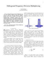
<strong>Synchronization</strong> and OFDM<br />
• <strong>Synchronization</strong> is an essential task for any digital communication<br />
system<br />
• It is a major design problem<br />
• OFDM is used for two k<strong>in</strong>d of systems<br />
• Broadcast-type systems such as DAB & DVB<br />
• Packet-switched networks such as <strong>WLAN</strong><br />
• <strong>Synchronization</strong> & OFDM<br />
<strong>Synchronization</strong> & OFDM<br />
• Broadcast-type systems transmits data cont<strong>in</strong>uously<br />
• The receiver can <strong>in</strong>itially spend relatively long time to acquire the signal (acquisition<br />
mode) and then switch to the track<strong>in</strong>g mode<br />
• <strong>WLAN</strong> systems have to use “s<strong>in</strong>gle-shot” synchronization<br />
• The synchronization has to be acquired dur<strong>in</strong>g a very short time after the start of the<br />
packet<br />
<strong>WLAN</strong> <strong>Synchronization</strong> 16.3.2004 © Hafeth Hourani 4
<strong>Synchronization</strong> <strong>in</strong> Packet-Switched Networks<br />
• In <strong>WLAN</strong>, the receiver has to acquire the synchronization <strong>in</strong> very short<br />
time<br />
• S<strong>in</strong>gle-Shot <strong>Synchronization</strong> . . .<br />
• To facilitate <strong>WLAN</strong> “s<strong>in</strong>gle-shot synchronization”, the IEEE 802.11a<br />
<strong>in</strong>cludes<br />
• Receiver tra<strong>in</strong><strong>in</strong>g <strong>in</strong>formation is needed cont<strong>in</strong>uously<br />
• To achieve good system throughput,<br />
<strong>WLAN</strong> <strong>Synchronization</strong> 16.3.2004 © Hafeth Hourani 5
Next . . .<br />
• Overview<br />
•Tim<strong>in</strong>g Estimation<br />
• Frequency <strong>Synchronization</strong><br />
• Channel Estimation<br />
• Summary<br />
<strong>WLAN</strong> <strong>Synchronization</strong> 16.3.2004 © Hafeth Hourani 6
Tim<strong>in</strong>g Estimation Overview<br />
Tim<strong>in</strong>g Estimation<br />
Packet<br />
<strong>Synchronization</strong><br />
Sample Clock<br />
Track<strong>in</strong>g<br />
Symbol<br />
<strong>Synchronization</strong><br />
Received Signal Energy<br />
Detection<br />
Double Slid<strong>in</strong>g W<strong>in</strong>dow<br />
Packet Detection<br />
Preamble Assisted Packet<br />
Detection<br />
<strong>WLAN</strong> <strong>Synchronization</strong> 16.3.2004 © Hafeth Hourani 7
Packet <strong>Synchronization</strong><br />
• The IEEE 802.11 MAC protocol is essentially a Random Access Network.<br />
• The receiver does not know exactly when a packet starts<br />
Packet Detection is needed . . .<br />
• Packet Detection<br />
The task of f<strong>in</strong>d<strong>in</strong>g an approximate estimate of the start of the<br />
preamble of an <strong>in</strong>com<strong>in</strong>g data packet<br />
• Packet Detection is the first synchronization algorithm that is<br />
performed<br />
The rest of the synchronization process is dependent on good<br />
packet detection performance<br />
<strong>WLAN</strong> <strong>Synchronization</strong> 16.3.2004 © Hafeth Hourani 8
• Packet detection test<br />
H<br />
H<br />
0<br />
1<br />
: Packet not present<br />
: Packet present<br />
• Test statement<br />
0<br />
1<br />
Packet Detection<br />
H : m < Thr ⇒ Packet not present<br />
n<br />
H : m ≥Thr ⇒Packet present<br />
n<br />
• The performance of packet detection can be measured with two<br />
probabilities:<br />
• Probability of detection P D<br />
• The probability of detect<strong>in</strong>g a packet when it is truly present<br />
• Probability of false alarm P FA<br />
• The probability that the test decides that a packet is present, when actually there is<br />
none<br />
<strong>WLAN</strong> <strong>Synchronization</strong> 16.3.2004 © Hafeth Hourani 9
Packet Detection Performance<br />
• P D should be as high as possible<br />
• P FA should be as small as possible<br />
• In general, <strong>in</strong>creas<strong>in</strong>g P D <strong>in</strong>creases P FA and decreas<strong>in</strong>g P D decreases<br />
P FA<br />
• The packet detection algorithm should be a compromise between<br />
P D and P FA<br />
• The false alarm is less severe error than not detect<strong>in</strong>g a packet at all<br />
• After a false alarm, the receiver will try to synchronize to<br />
nonexistent packet and will detect an error<br />
• Not detect<strong>in</strong>g a packet always results <strong>in</strong> loss of data<br />
A little higher P FA can be tolerated to guarantee good P D<br />
<strong>WLAN</strong> <strong>Synchronization</strong> 16.3.2004 © Hafeth Hourani 10
Packet Detection Methods<br />
Tim<strong>in</strong>g Estimation<br />
Packet<br />
<strong>Synchronization</strong><br />
Sample Clock<br />
Track<strong>in</strong>g<br />
Symbol<br />
<strong>Synchronization</strong><br />
Received Signal Energy<br />
Detection<br />
Double Slid<strong>in</strong>g W<strong>in</strong>dow<br />
Packet Detection<br />
Preamble Assisted Packet<br />
Detection<br />
<strong>WLAN</strong> <strong>Synchronization</strong> 16.3.2004 © Hafeth Hourani 11
Received Signal Energy (RSE) Detection<br />
• The algorithm:<br />
• F<strong>in</strong>d the start edge of the packet by measur<strong>in</strong>g the received signal<br />
energy<br />
• When there is no signal received, the received signal r n consists of noise<br />
only r n = w n<br />
• When the packet starts, the received energy is <strong>in</strong>creased by the signal<br />
component r n = w n + s n<br />
The packet can be detected as a change <strong>in</strong> the received energy level<br />
• Use the accumulated signal energy (m n )over a w<strong>in</strong>dow of length L<br />
L−1 L−1<br />
*<br />
n<br />
= ∑ n−k n−k = ∑ n−k<br />
k= 0 k=<br />
0<br />
m r r r<br />
2<br />
<strong>WLAN</strong> <strong>Synchronization</strong> 16.3.2004 © Hafeth Hourani 12
Received Signal Energy Detection (cont’d)<br />
Algorithm evaluation<br />
• Pros.<br />
• Simple algorithm<br />
• Cons.<br />
• The value of the threshold<br />
depends on the received<br />
signal energy<br />
• It is difficult to set a<br />
threshold to decide when a<br />
new packet is com<strong>in</strong>g<br />
m n<br />
Threshold 1<br />
Threshold 2<br />
Algorithm response<br />
Start of the packet edge<br />
IEEE 802.11a packet with SNR = 10 dB L = 32,<br />
<strong>WLAN</strong> <strong>Synchronization</strong> 16.3.2004 © Hafeth Hourani 13
Double Slid<strong>in</strong>g W<strong>in</strong>dow Detection (DSW)<br />
• The algorithm<br />
• Use two consecutive slid<strong>in</strong>g w<strong>in</strong>dows to calculate the received<br />
signal energy<br />
• Form the decision variable m n as a ratio of the total energy<br />
conta<strong>in</strong>ed <strong>in</strong>side the two w<strong>in</strong>dows<br />
• W<strong>in</strong>dows A and B are considered<br />
stationary relative to the slid<strong>in</strong>g<br />
packets<br />
• When only noise is received, the<br />
output is flat<br />
• The response of m n can be though of<br />
as a differentiator<br />
• The response is large when the<br />
<strong>in</strong>put level changes rapidly<br />
Packet<br />
W<strong>in</strong>dow A<br />
W<strong>in</strong>dow B<br />
M−1 M−1<br />
*<br />
n<br />
= ∑ n−m n−m = ∑ n−m<br />
m= 0 m=<br />
0<br />
a r r r<br />
L−1 L−1<br />
*<br />
n<br />
= ∑ n−l n−l = ∑ n−l<br />
l= 0 l=<br />
0<br />
b r r r<br />
<strong>WLAN</strong> <strong>Synchronization</strong> 16.3.2004 © Hafeth Hourani 14<br />
m<br />
n<br />
a<br />
=<br />
b<br />
n<br />
n<br />
2<br />
Thr<br />
2
• The result of the DSW does<br />
not depend on the total<br />
received power<br />
DSW (cont’d)<br />
• The DSW is a good approach<br />
m n<br />
Sample <strong>in</strong>dex<br />
Algorithm response<br />
IEEE 802.11 preamble, SNR = 10 dB<br />
<strong>WLAN</strong> <strong>Synchronization</strong> 16.3.2004 © Hafeth Hourani 15
Preamble Aided Packet Detection<br />
• In this approach, the known IEEE 802.11 preamble structure is<br />
<strong>in</strong>corporated <strong>in</strong>to the synchronization algorithm<br />
• The IEEE 802.11 was designed to aid the detection of the <strong>in</strong>com<strong>in</strong>g<br />
packet edge<br />
10 x 0.8 = 8.0 µ s 2 x 0.8 + 2 x 3.2 = 8.0 µ s<br />
A1 A2 A3 A4 A5 A6 A7 A8 A9 A10 CP C1 C2<br />
Packet Detection,<br />
AGC, Diversity<br />
Selection<br />
Coarse Freq.,<br />
Offset estimation,<br />
Symbol Tim<strong>in</strong>g<br />
Channel Estimation,<br />
F<strong>in</strong>e Frequency Offset Estimation<br />
Preamble parts:<br />
A1 A10 : short tra<strong>in</strong><strong>in</strong>g symbols (16 samples each)<br />
CP : cyclic prefix (32 samples) that protects C1 and C2 from ISI<br />
C1 & C2 : Long tra<strong>in</strong><strong>in</strong>g symbols (64 samples)<br />
<strong>WLAN</strong> <strong>Synchronization</strong> 16.3.2004 © Hafeth Hourani 16
Preamble Aided Detection (cont’d)<br />
• Delay and Correlate Algorithm<br />
• This algorithm utilizes the same DSW algorithm, but with tak<strong>in</strong>g<br />
advantage of the periodicity of the short tra<strong>in</strong><strong>in</strong>g symbols at start of<br />
the preamble<br />
L−1<br />
*<br />
n<br />
= ∑ n+ k n+ k+<br />
D<br />
k = 0<br />
c r r<br />
L−1 L−1<br />
*<br />
n<br />
= ∑ n+ k+ D n+ k+ D<br />
= ∑ n+ k+<br />
D<br />
k= 0 k=<br />
0<br />
2<br />
cn<br />
r<br />
m<br />
n<br />
n<br />
2<br />
p r r r<br />
⇒ =<br />
( p )<br />
n<br />
2<br />
2<br />
C ÷<br />
( ) * p<br />
D<br />
z − P n<br />
( ) 2<br />
Delay and Correlate Algorithm<br />
Two slid<strong>in</strong>g w<strong>in</strong>dows C & P<br />
The delay D = the period of the start of the preamble (e.g. D = 16 for IEEE 802.11)<br />
<strong>WLAN</strong> <strong>Synchronization</strong> 16.3.2004 © Hafeth Hourani 17<br />
c n<br />
m n
Preamble Aided Detection (cont’d)<br />
• When the received signal<br />
consists of only noise, the<br />
output c n of the delayed<br />
crosscorrelation is zeromean<br />
r.v.<br />
• Once the start of the<br />
packet is received, c n is a<br />
crosscorrelation of the<br />
identical short tra<strong>in</strong><strong>in</strong>g<br />
symbols, which causes m n<br />
to jump quickly to its<br />
maximum value<br />
• This jump gives a good<br />
estimate of the packet<br />
edge<br />
m n<br />
Sample <strong>in</strong>dex<br />
Algorithm response<br />
IEEE 802.11a packet with SNR = 10 dB<br />
jumps fast<br />
<strong>WLAN</strong> <strong>Synchronization</strong> 16.3.2004 © Hafeth Hourani 18
Packet Detection Methods<br />
Tim<strong>in</strong>g Estimation<br />
Packet<br />
<strong>Synchronization</strong><br />
Sample Clock<br />
Track<strong>in</strong>g<br />
Symbol<br />
<strong>Synchronization</strong><br />
Received Signal Energy<br />
Detection<br />
Double Slid<strong>in</strong>g W<strong>in</strong>dow<br />
Packet Detection<br />
Preamble Assisted Packet<br />
Detection<br />
<strong>WLAN</strong> <strong>Synchronization</strong> 16.3.2004 © Hafeth Hourani 19
Symbol Tim<strong>in</strong>g<br />
• Symbol Tim<strong>in</strong>g is the task of f<strong>in</strong>d<strong>in</strong>g the precise moment of when<br />
<strong>in</strong>dividual OFDM symbols start and end<br />
• Packet Detection provides an estimate of the packet edge<br />
• Symbol tim<strong>in</strong>g ref<strong>in</strong>es the estimate to the symbol level<br />
• Symbol tim<strong>in</strong>g is essential <strong>in</strong> OFDM<br />
• The symbol tim<strong>in</strong>g results def<strong>in</strong>es the DFT w<strong>in</strong>dow, i.e., the set of samples used to<br />
calculate DFT of each received OFDM symbol<br />
• The DFT result is then used to demodulate the subcarriers of the symbol<br />
<strong>WLAN</strong> <strong>Synchronization</strong> 16.3.2004 © Hafeth Hourani 20
Symbol Tim<strong>in</strong>g Algorithm<br />
• Symbol tim<strong>in</strong>g can be<br />
performed by calculat<strong>in</strong>g<br />
the crosscorrelation of the<br />
received signal r n and a<br />
known reference t k<br />
|m n |<br />
Correct symbol tim<strong>in</strong>g po<strong>in</strong>t<br />
L−1<br />
tˆ<br />
s<br />
= arg max ∑ r t<br />
n<br />
k = 0<br />
*<br />
n+<br />
k k<br />
In the equation, the value of n that corresponds to<br />
maximum absolute value of the crosscorrelation is the<br />
symbol tim<strong>in</strong>g estimate<br />
2<br />
Sample <strong>in</strong>dex<br />
The output of the crosscorrelator that uses the first 64 samples of<br />
the long tra<strong>in</strong><strong>in</strong>g symbols of IEEE 802.11 preamble<br />
SNR = 10 dB<br />
<strong>WLAN</strong> <strong>Synchronization</strong> 16.3.2004 © Hafeth Hourani 21
Packet Detection Methods<br />
Tim<strong>in</strong>g Estimation<br />
Packet<br />
<strong>Synchronization</strong><br />
Sample Clock<br />
Track<strong>in</strong>g<br />
Symbol<br />
<strong>Synchronization</strong><br />
Received Signal Energy<br />
Detection<br />
Double Slid<strong>in</strong>g W<strong>in</strong>dow<br />
Packet Detection<br />
Preamble Assisted Packet<br />
Detection<br />
<strong>WLAN</strong> <strong>Synchronization</strong> 16.3.2004 © Hafeth Hourani 22
Sample Clock <strong>Synchronization</strong><br />
• The task of track<strong>in</strong>g the sampl<strong>in</strong>g clock frequency<br />
• The sampl<strong>in</strong>g clock error has two ma<strong>in</strong> negative impacts:<br />
• A slow shift of the symbol tim<strong>in</strong>g po<strong>in</strong>t<br />
• Results <strong>in</strong> a subcarrier rotation<br />
• Loss of SNR due to <strong>in</strong>tercarrier <strong>in</strong>terference (ICI)<br />
• Results <strong>in</strong> a loss of subcarriers orthogonalilty<br />
• The normalized sampl<strong>in</strong>g error is given by<br />
t<br />
∆<br />
T′ −T<br />
=<br />
T<br />
T′ Receiver sampl<strong>in</strong>g period<br />
T Transmitter sampl<strong>in</strong>g period<br />
• The degradation <strong>in</strong> SNR was proved to be<br />
D<br />
n<br />
2<br />
⎛ π<br />
≈ 10log ⎜1+<br />
⎝ 3<br />
E<br />
N<br />
s<br />
0<br />
( kt )<br />
∆<br />
2<br />
⎞<br />
⎟<br />
⎠<br />
where k: Subcarrier <strong>in</strong>dex<br />
<strong>WLAN</strong> <strong>Synchronization</strong> 16.3.2004 © Hafeth Hourani 23
Sample Clock <strong>Synchronization</strong> (cont’d)<br />
• The amount of rotation angle experienced by different subcarriers is<br />
given by<br />
j<br />
e π<br />
T<br />
s<br />
2 kt∆l T u<br />
where k: Subcarrier <strong>in</strong>dex<br />
l : OFDM symbol <strong>in</strong>dex<br />
T s : Duration of the total OFDM symbol<br />
T u : Useful data portion of the symbol<br />
• The angle depends on both subcarrier <strong>in</strong>dex and the OFDM symbol<br />
<strong>in</strong>dex<br />
• Hence, the impact is larger on the outermost subcarriers and<br />
<strong>in</strong>crease with consecutive OFDM symbols<br />
• Large subcarrier rotation prevents the correct demodulation<br />
<strong>WLAN</strong> <strong>Synchronization</strong> 16.3.2004 © Hafeth Hourani 24
Estimat<strong>in</strong>g the Sampl<strong>in</strong>g Frequency Error<br />
• The approach of estimat<strong>in</strong>g the sampl<strong>in</strong>g frequency error rely on the<br />
pilot subcarriers<br />
• The pilot subcarriers are used to transmit known data called pilot<br />
symbols<br />
• The receiver can utilize the pilot symbols to perform synchronization<br />
functions<br />
• The sampl<strong>in</strong>g frequency offset is estimated by us<strong>in</strong>g the knowledge of<br />
the l<strong>in</strong>ear relationship between the phase rotation caused by the offset<br />
and the pilot subcarrier <strong>in</strong>dex<br />
<strong>WLAN</strong> <strong>Synchronization</strong> 16.3.2004 © Hafeth Hourani 25
Correct<strong>in</strong>g the Sampl<strong>in</strong>g Frequency Error<br />
• The rotation caused by the sampl<strong>in</strong>g frequency offset can be corrected<br />
with two ma<strong>in</strong> approaches<br />
• By adjust<strong>in</strong>g the sampl<strong>in</strong>g frequency for the receiver ADC<br />
n(t)<br />
s(t)<br />
H(f)<br />
r(t)<br />
ADC<br />
FFT<br />
Decision<br />
VCXO DPLL<br />
• By de-rotat<strong>in</strong>g the subcarrier after the DFT process<strong>in</strong>g<br />
n(t)<br />
s(t)<br />
H(f)<br />
r(t)<br />
ADC<br />
rob/stuff<br />
FFT<br />
POTOR<br />
Decision<br />
-<br />
-<br />
Fixed<br />
Xtal<br />
DPLL<br />
<strong>WLAN</strong> <strong>Synchronization</strong> 16.3.2004 © Hafeth Hourani 26
Next . . .<br />
• Overview<br />
• Tim<strong>in</strong>g Estimation<br />
•Frequency <strong>Synchronization</strong><br />
• Channel Estimation<br />
• Summary<br />
<strong>WLAN</strong> <strong>Synchronization</strong> 16.3.2004 © Hafeth Hourani 27
Frequency <strong>Synchronization</strong><br />
• OFDM is very sensitive to the carrier frequency offset<br />
• The carrier frequency error causes a significant SNR degradation <strong>in</strong><br />
OFDM<br />
• The degradation is caused by two ma<strong>in</strong> phenomena:<br />
• Subcarrier amplitude reduction<br />
• This is because the desired subcarrier is no longer sampled at the peak of the s<strong>in</strong>cfunction<br />
of DFT<br />
• ICI caused by neighbor<strong>in</strong>g subcarriers<br />
• The SNR degradation is approximated by<br />
10 Es<br />
SNRloss<br />
= ( πTf ∆ ) dB<br />
3ln10 N<br />
0<br />
<strong>WLAN</strong> <strong>Synchronization</strong> 16.3.2004 © Hafeth Hourani 28
Frequency <strong>Synchronization</strong> Approaches<br />
• The estimation algorithms of the carrier frequency offset <strong>in</strong> OFDM can<br />
be divided <strong>in</strong>to three types:<br />
• Data-aided algorithms<br />
• Based on special tra<strong>in</strong><strong>in</strong>g <strong>in</strong>formation embedded <strong>in</strong>to the transmitted signal<br />
• Non data-aided algorithms<br />
• The received signal is analyzed <strong>in</strong> the frequency doma<strong>in</strong><br />
• Cyclic prefix based algorithms<br />
• In <strong>WLAN</strong> applications, the first type is the most important (Data-aided)<br />
<strong>WLAN</strong> <strong>Synchronization</strong> 16.3.2004 © Hafeth Hourani 29
Next . . .<br />
• Overview<br />
• Tim<strong>in</strong>g Estimation<br />
• Frequency <strong>Synchronization</strong><br />
•Channel Estimation<br />
• Summery<br />
<strong>WLAN</strong> <strong>Synchronization</strong> 16.3.2004 © Hafeth Hourani 30
Channel Estimation<br />
• Channel Estimation is the task of estimat<strong>in</strong>g the frequency response of<br />
the radio channel<br />
• The impulse response of a time vary<strong>in</strong>g channel<br />
( )<br />
∑<br />
h τ t α t e δ τ τ t<br />
− 2 ( )<br />
; ( ) j π f cτn<br />
= t<br />
n<br />
( −<br />
n( ))<br />
n<br />
• The <strong>WLAN</strong> applications generally assume a quasistationary channel<br />
h<br />
= ∑<br />
−<br />
− 2 ( )<br />
( ) j π f cτn<br />
τ α t<br />
ne<br />
δ( τ τn)<br />
n<br />
• There are two approaches for handl<strong>in</strong>g the channel estimation<br />
• Frequency Doma<strong>in</strong><br />
• Time Doma<strong>in</strong><br />
<strong>WLAN</strong> <strong>Synchronization</strong> 16.3.2004 © Hafeth Hourani 31
Frequency Doma<strong>in</strong> Channel Estimation<br />
• The channel estimation is based on the tra<strong>in</strong><strong>in</strong>g data transmitted on<br />
every subcarrier<br />
• The tra<strong>in</strong><strong>in</strong>g symbols <strong>in</strong> the <strong>WLAN</strong> preamble are used for this purpose<br />
10 x 0.8 = 8.0 µ s 2 x 0.8 + 2 x 3.2 = 8.0 µ s<br />
A1 A2 A3 A4 A5 A6 A7 A8 A9 A10 CP C1 C2<br />
Packet Detection,<br />
AGC, Diversity<br />
Selection<br />
Coarse Freq.,<br />
Offset estimation,<br />
Symbol Tim<strong>in</strong>g<br />
Channel Estimation,<br />
F<strong>in</strong>e Frequency Offset Estimation<br />
Preamble parts:<br />
A1 A10 : short tra<strong>in</strong><strong>in</strong>g symbols (16 samples each)<br />
CP : cyclic prefix (32 samples) that protects C1 and C2 from ISI<br />
C1 & C2 : Long tra<strong>in</strong><strong>in</strong>g symbols (64 samples)<br />
• The contents of C1 and C2 are identical<br />
• Averag<strong>in</strong>g over C1 and C2 can be used to improve the quality of<br />
estimate<br />
<strong>WLAN</strong> <strong>Synchronization</strong> 16.3.2004 © Hafeth Hourani 32
Frequency Doma<strong>in</strong> Channel Estimation (cont’d)<br />
• After DFT process<strong>in</strong>g, the received tra<strong>in</strong><strong>in</strong>g symbols are<br />
R = H X + W Where R l,k : the received tra<strong>in</strong><strong>in</strong>g symbols<br />
lk , k k lk ,<br />
X k : the tra<strong>in</strong><strong>in</strong>g symbol<br />
H k : channel response<br />
W k : additive noise<br />
• The channel estimate can be calculated as the follow<strong>in</strong>g:<br />
1<br />
*<br />
Hˆ k<br />
= ( R1, k<br />
+ R2,<br />
k)<br />
Xk<br />
2<br />
1<br />
= ( H X + W + H X + W ) X<br />
2<br />
*<br />
k k 1, k k k 2, k k<br />
1<br />
= H X + ( W + W ) X<br />
2<br />
2 *<br />
k k 1, k 2, k k<br />
Select<strong>in</strong>g data tra<strong>in</strong><strong>in</strong>g amplitude to be equal to one<br />
1<br />
= H + ( W + W ) X<br />
2<br />
*<br />
k 1, k 2, k k<br />
The noise samples W 1,k and W 2,k are statistically <strong>in</strong>dependent<br />
<strong>WLAN</strong> <strong>Synchronization</strong> 16.3.2004 © Hafeth Hourani 33
Time Doma<strong>in</strong> Channel Estimation<br />
• The channel impulse response is estimated<br />
X<br />
r = h∗ x + w The received time doma<strong>in</strong> signal dur<strong>in</strong>g the two long tra<strong>in</strong><strong>in</strong>g symbols<br />
1, n n 1, n<br />
⎡ x1 x64 x63 … x64− L+<br />
2⎤<br />
⎢<br />
x2 x1 x64 x<br />
⎥<br />
⎢<br />
64− L+<br />
2 ⎥<br />
= ⎢ ⎥<br />
⎢ ⎥<br />
⎢x63 x62 x64−L<br />
⎥<br />
⎢<br />
⎣x64 x63 x ⎥<br />
64− L+<br />
1 ⎦<br />
The circular convolution<br />
matrix of the tra<strong>in</strong><strong>in</strong>g<br />
symbols, L the max length<br />
of impulse response that<br />
can be estimated<br />
2<br />
= ⎢h<br />
⎥<br />
3<br />
⎢ ⎥<br />
<strong>WLAN</strong> <strong>Synchronization</strong> 16.3.2004 © Hafeth Hourani 34<br />
h<br />
⎡ h1<br />
⎤<br />
⎢<br />
h<br />
⎥<br />
⎢ ⎥<br />
⎢ ⎥<br />
⎢<br />
⎣h<br />
⎥<br />
L ⎦<br />
ˆ 1 −1<br />
h= X ( r1, n<br />
+ r2,<br />
n)<br />
2<br />
1 −1<br />
= X ( Xh + w1+ Xh + w2)<br />
2<br />
−1 1 −1<br />
= X Xh+ X ( w1+<br />
w2)<br />
2<br />
1 −1<br />
= h+ X ( w1+<br />
w2)<br />
2<br />
The channel<br />
impulse response<br />
vector
Next . . .<br />
• Overview<br />
• Tim<strong>in</strong>g Estimation<br />
• Frequency <strong>Synchronization</strong><br />
• Channel Estimation<br />
•Summary<br />
<strong>WLAN</strong> <strong>Synchronization</strong> 16.3.2004 © Hafeth Hourani 35
Summary<br />
• <strong>Synchronization</strong> is an essential task <strong>in</strong> <strong>WLAN</strong><br />
• <strong>WLAN</strong> synchronization can be decomposed <strong>in</strong>to four ma<strong>in</strong> task:<br />
• Tim<strong>in</strong>g estimation<br />
• Sampl<strong>in</strong>g frequency estimation<br />
• Frequency <strong>Synchronization</strong><br />
• Channel Estimation<br />
• Tim<strong>in</strong>g estimation consists of two ma<strong>in</strong> task<br />
• The packet synchronization<br />
• The symbol synchronization<br />
<strong>WLAN</strong> <strong>Synchronization</strong> 16.3.2004 © Hafeth Hourani 36
References<br />
• OFDM Wireless LANs: A Theorethical and Practical Guide, Juha<br />
Heiskala, John Terry, Sams Publish<strong>in</strong>g 2002<br />
<strong>WLAN</strong> <strong>Synchronization</strong> 16.3.2004 © Hafeth Hourani 37
Thank You !<br />
<strong>WLAN</strong> <strong>Synchronization</strong> 16.3.2004 © Hafeth Hourani 38
Homework<br />
• Q1. In that equation <strong>in</strong> slide 12, we have accumulated the signal energy over a<br />
w<strong>in</strong>dow of size L. Why ?<br />
• Q2. In the double slid<strong>in</strong>g w<strong>in</strong>dow algorithm (presented <strong>in</strong> slide 14), the output of<br />
the receiver is flat when only noise is received. Why? And how does this algorithm<br />
solve the problems encountered when us<strong>in</strong>g s<strong>in</strong>gle w<strong>in</strong>dow?<br />
• Q3. In block diagram of the Preamble Assisted Detection algorithm (slide 17); what<br />
is the purpose of us<strong>in</strong>g w<strong>in</strong>dow P?<br />
• Q4. The most important frequency synchronization algorithm for <strong>WLAN</strong><br />
applications is the “Data-aided algorithms” (slide 29). Why? Where did we get such<br />
data to “aid” the frequency synchronization?<br />
<strong>WLAN</strong> <strong>Synchronization</strong> 16.3.2004 © Hafeth Hourani 39