

TM 9-2320-363-10 - JATONKAM35s HOME ON THE WEB
TM 9-2320-363-10 - JATONKAM35s HOME ON THE WEB
TM 9-2320-363-10 - JATONKAM35s HOME ON THE WEB

Create successful ePaper yourself
Turn your PDF publications into a flip-book with our unique Google optimized e-Paper software.
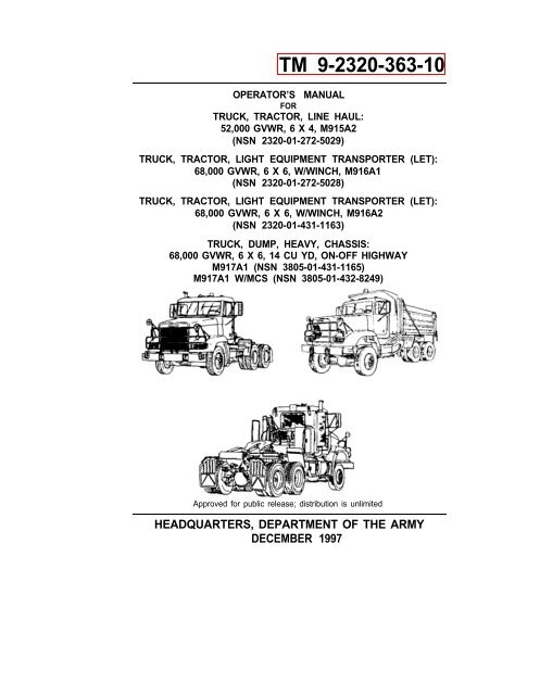
<strong>TM</strong> 9-<strong>2320</strong>-<strong>363</strong>-<strong>10</strong><br />
OPERATOR’S MANUAL<br />
FOR<br />
TRUCK, TRACTOR, LINE HAUL:<br />
52,000 GVWR, 6 X 4, M915A2<br />
(NSN <strong>2320</strong>-01-272-5029)<br />
TRUCK, TRACTOR, LIGHT EQUIPMENT TRANSPORTER (LET):<br />
68,000 GVWR, 6 X 6, W/WINCH, M916A1<br />
(NSN <strong>2320</strong>-01-272-5028)<br />
TRUCK, TRACTOR, LIGHT EQUIPMENT TRANSPORTER (LET):<br />
68,000 GVWR, 6 X 6, W/WINCH, M916A2<br />
(NSN <strong>2320</strong>-01-431-1163)<br />
TRUCK, DUMP, HEAVY, CHASSIS:<br />
68,000 GVWR, 6 X 6, 14 CU YD, <strong>ON</strong>-OFF HIGHWAY<br />
M917A1 (NSN 3805-01-431-1165)<br />
M917A1 W/MCS (NSN 3805-01-432-8249)<br />
Approved for public release; distribution is unlimited<br />
HEADQUARTERS, DEPAR<strong>TM</strong>ENT OF <strong>THE</strong> ARMY<br />
DECEMBER 1997
<strong>TM</strong> 9-<strong>2320</strong>-<strong>363</strong>-<strong>10</strong><br />
FOR INFORMATI<strong>ON</strong> <strong>ON</strong> FIRST AID, REFER TO FM 21-11.<br />
CARB<strong>ON</strong> M<strong>ON</strong>OXIDE (EXHAUST GASES) CAN KILL!<br />
Carbon monoxide is a colorless, odorless, deadly poison which, when breathed,<br />
deprives the body of oxygen and causes suffocation. Exposure to air containing carbon<br />
monoxide produces symptoms of headache, dizziness, loss of muscular control,<br />
apparent drowsiness, and coma. Permanent brain damage or death can result from<br />
severe exposure.<br />
Carbon monoxide occurs in exhaust fumes of internal combustion engines. Carbon<br />
monoxide can become dangerously concentrated under conditions of inadequate<br />
ventilation. The following precautions must be observed to ensure safety of personnel<br />
when engine of truck is operated.<br />
1. DO NOT operate truck engine in enclosed areas.<br />
2. DO NOT idle truck engine without adequate ventilation.<br />
3. DO NOT drive truck with inspection plates or cover plates removed.<br />
4. BE ALERT for exhaust poisoning symptoms. They are:<br />
• Headache<br />
• Dizziness<br />
• Sleepiness<br />
• Loss of muscular control<br />
5. If you see another person with exhaust poisoning symptoms:<br />
• Remove person from area.<br />
• Expose to fresh air.<br />
• Keep person warm.<br />
• Do not permit physical exercise.<br />
• Administer cardiopulmonary resuscitation (CPR), if necessary.<br />
• Notify a medic.<br />
6. BE AWARE. The field protective mask for nuclear-biological-chemical (NBC)<br />
protection will not protect you from carbon monoxide poisoning.<br />
The Best Defense Against Carbon Monoxide Poisoning Is Good Ventilation!<br />
a
<strong>TM</strong> 9-<strong>2320</strong>-<strong>363</strong>-<strong>10</strong><br />
BATTERlES<br />
• To avoid eye injury, eye protection is required when working around batteries. Do<br />
not smoke, use open flame, make sparks, or create other ignition sources around<br />
batteries. If a battery is giving off gases, it can explode and cause injury to personnel.<br />
Remove all jewelry such as rings, ID tags, watches, and bracelets. If jewelry<br />
or a tool contacts a battery terminal, a direct short will result in instant<br />
heating, damage to equipment, and injury to personnel.<br />
• Sulfuric acid contained in batteries can cause serious burns. If battery corrosion<br />
or electrolyte makes contact with skin, eyes, or clothing, take immediate action to<br />
stop the corrosive burning effects. Failure to follow these procedures may result<br />
in death or serious injury to personnel.<br />
a. Eyes. Flush with cold water for no less than 15 minutes and seek<br />
medical attention immediately.<br />
b. Skin. Flush with large amounts of cold water until all acid is removed.<br />
Seek medical attention as required.<br />
c. Internal. If corrosion or electrolyte is ingested, drink large amounts of<br />
water or milk. Follow with milk of magnesia, beaten egg, or vegetable<br />
oil. Seek medical attention immediately.<br />
d. Clothing/Equipment. Wash area with large amounts of cold water.<br />
Neutralize acid with baking soda or household ammonia.<br />
BRAKES<br />
• Do not use trailer handbrake to prevent trailer from jackknifing because this may<br />
cause trailer to jackknife. Modern airbrake systems are designed to deliver the<br />
right amount of air to all wheels to stop vehicle without jackknifing. Failure to follow<br />
this warning may result in death or injury to personnel or damage to equipment.<br />
• Do not use trailer handbrake as primary brake to keep tension on coupling system.<br />
This will cause undue tension on brakes and coupling which could result in<br />
injury to personnel or damage to equipment. Prevent problems with slack in fifth<br />
wheel by using good braking habits and adjusting coupling and braking systems<br />
properly.<br />
• When caging brakes, block wheels to keep truck from moving when brakes are<br />
released. Failure to follow this warning may result in death or injury to personnel<br />
or damage to equipment.<br />
b
<strong>TM</strong> 9-<strong>2320</strong>-<strong>363</strong>-<strong>10</strong><br />
• DO NOT use engine brake if road surfaces are slippery. Use of engine brake on<br />
wet, icy, or snow-covered roads could result in loss of vehicle control. Failure to<br />
• follow this warning could result in death or injury to personnel or damage to<br />
equipment.<br />
• Brake chamber contains spring under great pressure. To prevent personnel<br />
injury, never work directly behind chamber. If caging bolt will not engage properly,<br />
spring may be broken.<br />
• Do not remove clamp ring around spring brake chamber. It is under tension and<br />
can cause personnel injury if released.<br />
• When spring brakes are applied, vehicle will stop quickly which could result in<br />
injury to personnel. Also, vehicle cannot be driven again until malfunction is<br />
repaired and enough air supply is present for operation of service brakes.<br />
COMPRESSED AIR<br />
Compressed air used for cleaning or drying purposes, or for clearing restrictions,<br />
should never exceed 30 psi (207 kPa). Wear protective clothing (goggles/shield,<br />
gloves, etc.) and use caution to avoid injury to personnel.<br />
CTlS OPERATl<strong>ON</strong> (M917A1 AND M917A1 W/MCS)<br />
• When resuming operation on highway surfaces, be sure to reset CTIS selector<br />
panel to higher tire pressures. Operating vehicle with underinflated tires will<br />
cause premature tire wear or damage to tires causing unsafe driving conditions.<br />
Failure to follow this warning may result in death or injury to personnel.<br />
• Always wear eye protection when disconnecting CTIS air lines. Residual air in<br />
tire(s) and air line(s) will be expelled even though tire(s) is flat. Failure to follow<br />
this warning could cause serious eye injury.<br />
DIESEL FUEL HANDLING<br />
• DO NOT smoke or permit any open flame in area of truck while you are servicing<br />
diesel fuel system. Be sure hose nozzle is grounded against filler tube during<br />
refueling to prevent static electricity. Failure to follow this warning may result in<br />
injury to personnel or equipment damage.<br />
• DO NOT perform fuel system checks, inspections, or maintenance while smoking<br />
or near fire, flames, or sparks. Fuel may ignite, causing damage to vehicle and<br />
injury or death to personnel.<br />
c
<strong>TM</strong> 9-<strong>2320</strong>-<strong>363</strong>-<strong>10</strong><br />
• Fuel tank cap may become hot during vehicle operation. Use hand protection<br />
when removing fuel cap.<br />
DRY CLEANING SOLVENT<br />
Dry cleaning solvent, P-D-680, is toxic and flammable. Always wear protective goggles<br />
and gloves, and use only in a well-ventilated area. Avoid contact with skin, eyes,<br />
and clothes, and DO NOT breathe vapors. DO NOT use near open flame or excessive<br />
heat. The solvent’s flash point is <strong>10</strong>0 o F-138°F (38 o C-59 o C). If you become dizzy<br />
while using cleaning solvent, immediately get fresh air and medical help. If solvent<br />
contact eyes, immediately wash your eyes and get medical aid.<br />
HAZARDOUS WASTE DISPOSAL<br />
When servicing this vehicle, performing maintenance, or disposing of materials such<br />
as engine coolant, transmission fluid, lubricants, battery acids or batteries, and<br />
CARC paint, consult your unit/local hazardous waste disposal center or safety office<br />
for local regulatory guidance. If further information is needed, please contact The<br />
Army Environmental Hotline at 1-800-872-3845.<br />
d
<strong>TM</strong> 9-<strong>2320</strong>-<strong>363</strong>-<strong>10</strong><br />
NBC EXPOSURE<br />
If NBC exposure is suspected, all air cleaner media should be handled by personnel<br />
wearing protective equipment. Consult your NBC Officer or NBC NCO for appropriate<br />
handling or disposal procedures.<br />
IF NBC EXPOSURE IS SUSPECTED ALL AIR FlL-<br />
TER MEDIA WlLL BE HANDLED BY PERS<strong>ON</strong>NEL<br />
WEARING FULL NBC PROTECTIVE EQUIP-<br />
MENT. SEE OPERATOR/MAINTENANCE MAN-<br />
UAL.<br />
7690-01-114-3702<br />
To order this NBC decal use:<br />
National Stock Number (NSN) - 7690-01-114-3702<br />
Part Number (PN) - 12296626<br />
Commercial and Government Entity Code (CAGEC) - 19207<br />
PRESSURIZED COOLING AND HYDRAULIC SYSTEMS<br />
• DO NOT remove radiator cap unless engine is cold. Remove cap in two steps.<br />
First, place thick cloth over cap and slowly turn cap left to first stop. Pause and<br />
allow pressure to escape. Turn cap further left until it can be removed. This is a<br />
pressurized cooling system and escaping steam, hot water, or coolant will cause<br />
serious burns.<br />
• DO NOT remove fill cap when hydraulic fluid is hot. Hydraulic tank is pressurized<br />
to 5 psi (34 kPa). Remove cap slowly to prevent serious burns.<br />
e
<strong>TM</strong> 9-<strong>2320</strong>-<strong>363</strong>-<strong>10</strong><br />
SLAVE STARTlNG<br />
• When slave starting truck, use NATO slave cables that DO NOT have loose or<br />
missing insulation.<br />
• DO NOT proceed if suitable cables are not available.<br />
• DO NOT use civilian-type jumper cables.<br />
TlRE CHANGING<br />
Whenever inner and/or outer wheel lug nuts require tightening or a wheel has been<br />
removed and replaced, lug nuts must be torqued to the required torque. Failure to follow<br />
this warning may result in serious injury to personnel and damage to equipment.<br />
TRUCK OPERATI<strong>ON</strong><br />
BE ALERT for personnel in area while operating truck. Always check to ensure<br />
area is clear of personnel and obstructions before moving out. Failure to follow<br />
this warning may result in serious injury or death to personnel.<br />
Use of seat belts while operating vehicle is mandatory. Fasten belt BEFORE driving.<br />
Trying to fasten three-point belt while driving creates a hazardous condition.<br />
Failure to follow this warning may result in death or injury to personnel.<br />
Serious injury may result if head clearance is not adequate while sitting in seat.<br />
Before driving or riding in vehicle, ensure there is adequate clearance at maximum<br />
upward travel of seat.<br />
Check Engine button is used for diagnostic purposes only. DO NOT push Check<br />
Engine button during vehicle operation because engine will slow down to an idle,<br />
which could cause hazardous operating conditions. Return to operating mode by<br />
releasing accelerator pedal and allowing engine to return to idle speed. Failure to<br />
follow this warning may result in death or injury to personnel.<br />
Use caution when coupling to or uncoupling from tractor truck. Be alert for personnel<br />
in area. Ensure that hands, arms, and body are clear of potential pinch<br />
points. Failure to follow this warning may result in injury to personnel.<br />
Operating truck with an underinflated or defective tire may lead to tire failure and<br />
loss of steering control. Damage to equipment or injury to personnel may result.<br />
These vehicles have been designed to operate safely and efficiently within the<br />
limits specified in this <strong>TM</strong>. Operation beyond these limits is prohibited in accordance<br />
with AR 70-1 without written approval from: Commander, U.S. Army Tankautomotive<br />
and Armaments Command, ATTN: AMSTA-DSA-CS, Warren, Ml<br />
48397-5000.<br />
f
<strong>TM</strong> 9-<strong>2320</strong>-<strong>363</strong>-<strong>10</strong><br />
•<br />
•<br />
•<br />
WINCH OPERATI<strong>ON</strong> (M916A1 AND M916A2)<br />
Always wear heavy gloves when handling winch cable. Never allow cable to run<br />
through hands; frayed cable can cut you. Never operate winch with less than four<br />
turns of cable on drum. Keep cable coils tight and close together on drum while<br />
winching. Failure to follow this warning may result in injury to personnel.<br />
Hearing protection is required for operator and personnel working around winch<br />
station during operation.<br />
DO NOT use winch for moving or lifting people. Serious injury could result.<br />
•<br />
•<br />
•<br />
•<br />
WORK SAFETY<br />
Use caution when lifting or handling wheel and tire assembly. It is heavy and<br />
could cause injury if improperly lifted or if it falls on you.<br />
Hydraulic jack is intended only for lifting truck, not for supporting vehicle to perform<br />
maintenance. Do not get under truck after it is raised unless it is properly<br />
supported with blocks or jackstands. Failure to observe this warning may result in<br />
death or injury to personnel.<br />
Ether is highly flammable and explosive. DO NOT perform ether quick-start system<br />
checks or inspections while smoking or near fire, flame, or sparks. Failure to<br />
follow this warning may cause a fire and explosion, causing serious injury or<br />
death to personnel.<br />
Handle must be used when operating release lever. Failure to do so could result<br />
in injury to personnel.<br />
Failure to completely turn <strong>ON</strong> or OFF air cutoff valve will cause loss of brakes on<br />
trailer or truck.<br />
Improper use of lifting equipment and improper attachment of cables to vehicle<br />
can result in serious personnel injury and equipment damage. Observe all standard<br />
rules of safety.<br />
g
<strong>TM</strong> 9-<strong>2320</strong>-<strong>363</strong>-<strong>10</strong><br />
•<br />
•<br />
WATER DISTRIBUTOR TOWING<br />
DO NOT tow 6,000 gallon water distributors with a partial load except when in<br />
use on construction sites and at a maximum speed of <strong>10</strong> mph. When towing outside<br />
of construction sites, either drain water distributor empty (preferred) or fill to<br />
capacity. Failure to follow this warning could result in unsafe driving conditions<br />
causing serious injury or death to personnel and damage to equipment.<br />
When towing 6,000 gallon water distributor, fifth wheel must be in rear setting<br />
(LOAD HAUL-172) and travel lockout must be engaged to prevent side-to-side<br />
oscillation of water distributor. Failure to follow this warning could result in unsafe<br />
driving conditions causing serious injury or death to personnel and damage to<br />
equipment.<br />
h
<strong>TM</strong> 9-2350-<strong>363</strong>-<strong>10</strong><br />
TECHNICAL MANUAL<br />
<strong>TM</strong> 9-<strong>2320</strong>-<strong>363</strong>-<strong>10</strong> *<br />
HEADQUARTERS<br />
DEPAR<strong>TM</strong>ENT OF <strong>THE</strong> ARMY<br />
Washington, D.C., 30 December 1997<br />
OPERATOR’S MANUAL<br />
FOR<br />
TRUCK, TRACTOR, LINE HAUL:<br />
52,000 GVWR, 6 X 4, M915A2<br />
(NSN <strong>2320</strong>-01-272-5029)<br />
TRUCK, TRACTOR, LIGHT EQUIPMENT TRANSPORTER (LET):<br />
68,000 GVWR, 6 X 6, W/WINCH, M916A1<br />
(NSN <strong>2320</strong>-01-272-5028)<br />
TRUCK, TRACTOR, LIGHT EQUIPMENT TRANSPORTER (LET):<br />
68,000 GVWR, 6 X 6, W/WINCH, M916A2<br />
(NSN <strong>2320</strong>-01-431-1163)<br />
TRUCK, DUMP, HEAVY, CHASSIS:<br />
68,000 GVWR, 6 X 6, 14 CU YD, <strong>ON</strong>-OFF HIGHWAY<br />
M917A1 (NSN 3805-01-431-1165)<br />
M917A1 W/MCS (NSN 3805-01-432-8249)<br />
Approved for Public Release; Distribution is Unlimited<br />
REPORTING ERRORS AND RECOMMENDING IMPROVEMENTS<br />
You can help improve this manual. If you find any mistakes or if you know<br />
of a way to improve the procedures, please let us know. Mail your letter,<br />
DA Form 2028 (Recommended Changes to Publications and Blank<br />
Forms) or DA Form 2028-2, located in the back of this manual, direct to:<br />
Commander, U.S. Army Tank-automotive and Armaments Command,<br />
ATTN: AMSTA-AC-NML, Rock Island, Illinois 61299-7630. A reply will be<br />
furnished to you.<br />
You may also provide DA Form 2028-2 information to TACOM via datafax<br />
or e-mail.<br />
• TACOM’s datafax number for AMSTA-AC-NML is: DSN 793-<br />
0726 or Commercial (309) 782-0726<br />
• TACOM’s e-mail address is: amsta-ac-nml@ria-emh2.army.mil<br />
* This manual supersedes <strong>TM</strong> 9-<strong>2320</strong>-<strong>363</strong>-<strong>10</strong>, 5 Nov 1991 and all changes.<br />
i
<strong>TM</strong> 9-<strong>2320</strong>-<strong>363</strong>-<strong>10</strong><br />
CHAPTER 1<br />
Section I.<br />
Section II.<br />
Section III.<br />
CHAPTER 2<br />
Section I.<br />
Section II.<br />
Section Ill.<br />
Section IV.<br />
CHAPTER 3<br />
Section I.<br />
Section II.<br />
Section III.<br />
APPENDIX A<br />
APPENDIX B<br />
APPENDIX C<br />
APPENDIX D<br />
APPENDIX E<br />
APPENDIX F<br />
TABLE OF C<strong>ON</strong>TENTS<br />
INTRODUCTI<strong>ON</strong>.. .....................................................<br />
General Information.. .................................................<br />
Equipment Description and Data.. .............................<br />
Principles of Operation.. ............................................<br />
OPERATING INSTRUCTI<strong>ON</strong>S .................................<br />
Description and Use of Operator’s Controls<br />
and Indicators ............................................................<br />
Preventive Maintenance Checks and<br />
Services (PMCS). ......................................................<br />
Operation Under Usual Conditions ............................<br />
Operation Under Unusual Conditions ........................<br />
OPERATOR MAINTENANCE ...................................<br />
Lubrication Instructions .............................................<br />
Operator Troubleshooting Procedures......................<br />
Operator Maintenance.. .............................................<br />
REFERENCES.. ........................................................<br />
COMP<strong>ON</strong>ENTS OF END ITEM AND<br />
BASIC ISSUE ITEMS LISTS.. ...................................<br />
ADDITI<strong>ON</strong>AL AUTHORIZATI<strong>ON</strong> LIST.. ....................<br />
EXPENDABLE AND DURABLE ITEMS LIST.. .........<br />
STOWAGE AND DECAL, DATA PLATE, AND<br />
STENCIL GUIDE.......................................................<br />
LUBRICATI<strong>ON</strong> INSTRUCTI<strong>ON</strong>S ..............................<br />
INDEX .......................................................................<br />
Page<br />
1-1<br />
1-1<br />
1-5<br />
1-25<br />
2-1<br />
2-1<br />
2-33<br />
2-81<br />
2-121<br />
3-1<br />
3-1<br />
3-3<br />
3-17<br />
A-1<br />
B-1<br />
C-1<br />
D-1<br />
E-1<br />
F-1<br />
Index 1<br />
ii
<strong>TM</strong> 9-<strong>2320</strong>-<strong>363</strong>-<strong>10</strong><br />
HOW TO USE THIS MANUAL<br />
This manual is designed to help you operate and maintain the M915 Family of<br />
Vehicles.<br />
FEATURES OF THIS MANUAL:<br />
• A table of contents is provided at the beginning of this manual. An index of all<br />
paragraphs contained within a section is found at the beginning of each section.<br />
• WARNINGs, CAUTI<strong>ON</strong>s, NOTEs, subject headings, and other important information<br />
are highlighted in BOLD print as a visual aid.<br />
A WARNING indicates a hazard which can result in death or<br />
serious injury.<br />
A CAUTI<strong>ON</strong> is a reminder of safety practices or directs attention<br />
to usage practices that may result in damage to equipment.<br />
NOTE<br />
A NOTE is a statement containing information that will make the<br />
procedure easier to perform.<br />
• Statements and words of particular importance are printed in CAPITAL LET-<br />
TERS to create emphasis.<br />
• Instructions are located with illustrations that show the specific task on which the<br />
operator is working.<br />
• Dashed leader lines used in illustrations indicate that called out items are not visible<br />
(i.e., they are located within the structure). Dashed leader lines in the Lubrication<br />
Chart indicate that lubrication is required on BOTH sides of the equipment.<br />
• Technical instructions include metric units in addition to standard units. A metric<br />
conversion chart is provided on the inside back cover.<br />
• An alphabetical index is provided at the end of the manual to assist in locating<br />
information not readily found in the table of contents.<br />
FOLLOW <strong>THE</strong>SE GUIDELINES WHEN YOU USE THIS MANUAL:<br />
• Read through this manual and become familiar with its contents before attempting<br />
to operate or maintain the truck.<br />
• A warning summary is provided at the beginning of this manual and should be<br />
read before attempting to operate or maintain the truck.<br />
iii/(iv Blank)
<strong>TM</strong> 9-<strong>2320</strong>-<strong>363</strong>-<strong>10</strong><br />
CHAPTER 1<br />
INTRODUCTI<strong>ON</strong><br />
Section I. GENERAL INFORMATI<strong>ON</strong><br />
Paragraph<br />
Number<br />
Paragraph Title<br />
Page<br />
Number<br />
1-1. Scope ........................................... 1-1<br />
1-2. Maintenance Forms and Procedures. .................. 1-2<br />
1-3. Corrosion Prevention and Control (CPC) ............... 1-2<br />
1-4. Destruction of Army Materiel to Prevent Enemy Use ...... 1-2<br />
1-5. Reporting Equipment Improvement Recommendations (EIRs) 1-3<br />
1-6. Warranty Information. .............................. 1-3<br />
1-7. Nomenclature Cross-Reference List ................... 1-3<br />
1-8. List of Abbreviations ............................... 1-3<br />
1-1. SCOPE.<br />
a. Type of Manual.<br />
(1) This manual is for use in operating and maintaining the M915<br />
Family of Vehicles, to include the chassis of the M917A1 and M917A1 w/MCS (Material<br />
Control System) dump truck.<br />
(2) For operation and maintenance of the M917A1 and M917A1<br />
w/MCS dump truck body, refer to <strong>TM</strong> 5-3805-264-14&P.<br />
b. Equipment Name and Model Number.<br />
(1) Truck, Tractor, Line Haul: 52,000 GVWR, 6 X 4, M915A2<br />
(2) Truck, Tractor, Light Equipment Transporter (LET): 68,000<br />
GVWR, 6 X 6, w/Winch, M916A1 and M916A2<br />
(3) Truck, Dump, Heavy, Chassis: 68,000 GVWR, 6 X 6, 14 Cu<br />
Yd, On-Off Highway, M917A1 and M917A1 w/MCS.<br />
c. Purpose of Equipment.<br />
(1) The M915A2 truck tractor is a 6 X 4 prime mover of semitrailers<br />
used primarily to transport containers, bulk cargo, and petroleum products over<br />
primary and secondary roads under worldwide climatic conditions in a military environment.<br />
1-1
<strong>TM</strong> 9-<strong>2320</strong>-<strong>363</strong>-<strong>10</strong><br />
1-1. SCOPE (Con’t).<br />
(2) The M916A1 and M916A2 truck tractors are 6 X 6 prime<br />
movers of low-bed semitrailers used primarily to transport heavy engineer equipment<br />
over primary and secondary roads, and off-road, under worldwide climatic conditions<br />
in a military environment.<br />
(3) The M917A1 and M917A1 w/MCS are 6 X 6 dump trucks<br />
used to transport, dump, or spread asphalt, aggregate, dirt, and similar materials over<br />
primary and secondary roads and off-road.<br />
1-2. MAINTENANCE FORMS AND PROCEDURES.<br />
Department of the Army forms and procedures used for the equipment will<br />
be those prescribed by DA Pam 738-750, Functional User’s Manual for the Army<br />
Maintenance Management System (TAMMS), as contained in the Maintenance Management<br />
Update.<br />
1-3. CORROSI<strong>ON</strong> PREVENTI<strong>ON</strong> AND C<strong>ON</strong>TROL (CPC).<br />
a. Corrosion Prevention and Control (CPC) of Army materiel is a continuing<br />
concern. It is important that any corrosion problems with this item be reported<br />
so that the problem can be corrected and improvements can be made to prevent the<br />
problem in future items.<br />
b. While corrosion is typically associated with rusting of metals, it can<br />
also include deterioration of other materials, such as rubber and plastic. Unusual<br />
cracking, softening, swelling, or breaking of these materials may be a corrosion problem.<br />
If a corrosion problem is identified, it can be reported using SF Form 368 (Product<br />
Quality Deficiency Report). Use of key words such as “corrosion,” “rust,”<br />
“deterioration,” or “cracking” will ensure that the information is identified as a CPC<br />
problem. The form should be submitted to the address specified in DA Pam 738-750.<br />
1-4. DESTRUCTI<strong>ON</strong> OF ARMY MATERIEL TO PREVENT<br />
ENEMY USE.<br />
244-6.<br />
For destruction of Army materiel to prevent enemy use, refer to <strong>TM</strong> 750-<br />
1-2
<strong>TM</strong> 9-<strong>2320</strong>-<strong>363</strong>-<strong>10</strong><br />
1-5. REPORTlNG EQUIPMENT IMPROVEMENT RECOMMEN-<br />
DATI<strong>ON</strong>S (ElRs).<br />
If your truck needs improvement, let us know. Send us an EIR. You, the<br />
user, are the only one who can tell us what you don’t like about your equipment. Let<br />
us know why you don’t like the design or performance. Put it on an SF Form 368<br />
(Product Quality Deficiency Report). Mail it to us at: Commander, U.S. Army Tankautomotive<br />
and Armaments Command, ATTN: AMSTA-AC-NML, Rock Island, Illinois<br />
61299-7630. We’ll send you a reply.<br />
1-6. WARRANTY INFORMATI<strong>ON</strong>.<br />
The vehicles are warranted by Freightliner Corporation in accordance with<br />
TB 9-<strong>2320</strong>-<strong>363</strong>-15. Warranty starts on the date found in block 23, DA Form 2408-9 in<br />
the logbook. Report all defects in material or workmanship to your supervisor, who<br />
will take appropriate action through your Unit Maintenance shop.<br />
1-7. NOMENCLATURE CROSS-REFERENCE LIST.<br />
Common Name<br />
Official Nomenclature<br />
Cable ......................................................Wire Rope<br />
Cold Start System. . . . . . . . . . . . . . . . . . . . . . . . . . . Ether Quick-Start System<br />
Differential Lock/Unlock . . . . . . . . . . . . . . . .Interaxle Lockout (M915A2), All-Wheel Drive<br />
(All Except M915A2)<br />
Engine Coolant . . . . . . . . . . . . . . . . . . . . Antifreeze, Ethylene Glycol Mixture<br />
Gladhand. . . . . . . . . . . . . . . . . . . . . . . . . . . Quick Disconnect Coupling<br />
Jake Brake . . . . . . . . . . . . . . . . . . . . . . . . . . . . . Engine Brake<br />
Komfort Loc® . . . . . . . . . . . . . . . . . . . . . . . . Seat Belt Adjustment<br />
No Spin@. . . . . . . . . . . . . . . . Automatic Locking Positive Traction Differential<br />
1-8. LIST OF ABBREVIATI<strong>ON</strong>S.<br />
Abbreviation<br />
NOTE<br />
Refer to ML-STD-12D for standard abbreviations.<br />
Definition<br />
AAL . . . . . . . . . . . . . . . . . . . . . . . Additional Authorization List<br />
ABS . . . . . . . . . . . . . . . . . . . . . . . . Anti-Lock Brake System<br />
Bll . . . . . . . . . . . . . . . . . . . . . . . . . . . Basic Issue Items<br />
C . . . . . . . . . . . . . . . . . . . . . . . . .Centigrade or Celsius<br />
1-3
<strong>TM</strong> 9-<strong>2320</strong>-<strong>363</strong>-<strong>10</strong><br />
1-8. LIST OF ABBREVIATI<strong>ON</strong>S (Con’t).<br />
Abbreviation<br />
CID<br />
cm<br />
COEI<br />
CTIS<br />
ECU<br />
F<br />
GCWR<br />
GVWR.<br />
kg<br />
kph<br />
Iph<br />
MCS<br />
PMCS<br />
PTO<br />
Definition<br />
. . . . . . . . . . . . . . . . . . . . . . . . . . Cubic Inch Displacement<br />
. . . . . . . . . . . . . . . . . . . . . . . . . . . . . . . . . . . . Centimeter<br />
. . . . . . . . . . . . . . . . . . . . . . . . . Components of End Item<br />
. . . . . . . . . . . . . . . . . . . . . . . . . . .Central Tire Inflation System<br />
. . . . . . . . . . . . . . . . . . . . . . . . . . . . . Electronic Control Unit<br />
........................................ Fahrenheit<br />
. . . . . . . . . . . . . . . . . . . . . . Gross Combination Weight Rating<br />
. . . . . . . . . . . . . . . . . . . . . . . . . Gross Vehicle Weight Rating<br />
. . . . . . . . . . . . . . . . . . . . . . . . . . . . . . . . . . . . Kilogram<br />
................................ Kilometers per Hour<br />
..................................... Liters per Hour<br />
.............................. Material Control System<br />
. . . . . . . . . . . . . . . . Preventive Maintenance Checks and Services<br />
. . . . . . . . . . . . . . . . . . . . . . . . . . . . . . Power Take-Off<br />
1-4
<strong>TM</strong> 9-<strong>2320</strong>-<strong>363</strong>-<strong>10</strong><br />
Section II.<br />
EQUIPMENT DESCRIPTI<strong>ON</strong> AND DATA<br />
Paragraph<br />
Page<br />
Number Paragraph Title Number<br />
1-9.<br />
1-<strong>10</strong>.<br />
1-11.<br />
1-12.<br />
Equipment Characteristics, Capabilities, and Features . . . . 1-5<br />
Location and Description of Major Components. . . . . . . . . . 1-6<br />
Differences Between Models . . . . . . . . . . . . . . . . . . . . . . . . . 1-15<br />
Equipment Data . . . . . . . . . . . . . . . . . . . . . . . . . . . . . 1-16<br />
1-9. EQUIPMENT CHARACTERISTICS, CAPABILITIES, AND<br />
FEATURES.<br />
a. Characteristics.<br />
(1) The M915A2 is used to transport M871, M872, and M<strong>10</strong>62<br />
semitrailers on line haul missions. It has a Gross Vehicle Weight Rating (GVWR) of<br />
52,000 lb (23,608 kg) and is equipped with a two-way oscillating, sliding fifth wheel<br />
compatible with a two-inch kingpin. Maximum towed load on kingpin is 30,000 lb<br />
(13,620 kg).<br />
(2) The M916A1 and M916A2 are used to transport M172 and<br />
M870 semitrailers loaded with heavy engineer equipment and 60PRS and WD6S<br />
6,000 gallon water distributors over primary and secondary roads and off-road. They<br />
have a GVWR of 68,000 lb (30,872 kg) and are equipped with a 45,000 lb (20,430<br />
kg) winch, a tail roller, and a four-way oscillating, sliding fifth wheel compatible with a<br />
3 1/2-inch kingpin. Maximum towed load on kingpin is 40,000 lb (18,160 kg).<br />
(3) The M917A1 and M917A1 w/MCS have a GVWR of 68,000<br />
lb (30,872 kg), a 14 cu yd (<strong>10</strong>.7 m 3 ) dump body capacity, and an 18.5 ton (16.8 metric<br />
ton) load capability. They are equipped with a Central Tire Inflation System (CTIS)<br />
which allows operation across a wide variety of terrain.<br />
b. Capabilities and Features.<br />
(1) While operating on Class I roads, the fully loaded M915A2<br />
can maintain a speed of 55 mph (88 kph) on level roads and 29 mph (47 kph) while<br />
ascending a 3 percent grade. It has a minimum turning diameter, curb-to-curb, of 53<br />
ft 9 in. (16.4 m).<br />
(2) While operating on Class I roads, all other trucks can maintain<br />
a speed of 55 mph (88 kph) on level roads and 25 mph (40 kph) while ascending<br />
a 3 percent grade.<br />
(3) Average cruising ranges at Gross Combination Weight Rating<br />
(GCWR) with a full tank of fuel will vary based on conditions (e.g., varying loads,<br />
prolonged idle, PTO usage, off-road driving, and climatic conditions). Cruising range<br />
is optimally 300 miles (483 km).<br />
1-5
<strong>TM</strong> 9-<strong>2320</strong>-<strong>363</strong>-<strong>10</strong><br />
1-9. EQUIPMENT CHARACTERISTICS, CAPABILITIES, AND<br />
FEATURES (Con’t).<br />
(4) The M916A1 and M916A2 have a transmission-mounted<br />
PTO which powers the winch. The PTO on the M917A1 and M917A1 w/MCS powers<br />
the dump body controls (<strong>TM</strong> 5-3805-264-14&P).<br />
(5) The M915A2 and M916A1 are equipped with an instrument<br />
panel mounted tachograph which registers and records data related to truck ground<br />
speed, engine speed, and distance traveled. This data is stored on a 7-day graph for<br />
a permanent record. All other models are equipped with a Datalogger which is a data<br />
processing module that provides data storage capability and records in detail the performance<br />
and utilization of the vehicle. Datalogger memory can store over a month of<br />
data for use by maintenance and management personnel. There is no operator interference<br />
with the Datalogger.<br />
models:<br />
(6) The following capabilities and features are common to all<br />
(a) air-activated front and rear non-asbestos cam brakes<br />
with a four-channel anti-lock brake system (ABS) to provide significantly improved<br />
handling and braking during emergency stops;<br />
(b) operation in temperatures from -25°F (-32°C) to +125 o F<br />
(+52 o C), and to -40°F (-40°C) with arctic kit installed;<br />
(c) start and climb capability of a 20 percent grade at<br />
GCWR in both forward and reverse directions;<br />
(d) fording capability up to 20 in. (51 cm) deep for 5 minutes<br />
without damage or requiring maintenance before operations can continue;<br />
(e) two-passenger aluminum corrosion-proof cab with a 90<br />
degree tilt-forward hood for service accessibility;<br />
(f) six cylinder, 12.7 liter, 400 horsepower, in-line diesel<br />
engine built by Detroit Diesel;<br />
(g)<br />
Allison HT-740 four-speed automatic transmission.<br />
1-<strong>10</strong>. LOCATl<strong>ON</strong> AND DESCRlPTl<strong>ON</strong> OF MAJOR COMP<strong>ON</strong>-<br />
ENTS.<br />
a. M915A2, M916A1, and M916A2.<br />
Key Component Description<br />
1 Marker Clearance Indicate outline of truck.<br />
Lights<br />
2 Air Horn Provides an audible alert.<br />
1-6
<strong>TM</strong> 9-<strong>2320</strong>-<strong>363</strong>-<strong>10</strong><br />
1-<strong>10</strong>. LOCATI<strong>ON</strong> AND DESCRIPTI<strong>ON</strong> OF MAJOR COMPO-<br />
NENTS (Con’t).<br />
M916A1 AND M916A2<br />
Key Component Description<br />
3 Side Mirrors Provide driver with a view of sides of truck.<br />
4 Grabhandles Provide a hand hold for personnel climbing on truck.<br />
5 Utility Power Supplies power for work lights. Located on both<br />
Receptacle<br />
sides of truck.<br />
6 Spare Wheel and Tire Extra wheel and tire used in case of a flat tire.<br />
1-7
<strong>TM</strong> 9-<strong>2320</strong>-<strong>363</strong>-<strong>10</strong><br />
1-<strong>10</strong>. LOCATI<strong>ON</strong> AND DESCRIPTI<strong>ON</strong> OF MAJOR COMPO-<br />
NENTS (Con’t).<br />
M916A1 AND M916A2<br />
Key Component Description<br />
7 Battery Box and<br />
Steps<br />
Holds vehicle batteries and provides steps to<br />
access cab.<br />
8 Front Service Lights Include headlights and turn signals.<br />
9 Sling Points Provide attachment point for slings.<br />
<strong>10</strong> Blackout Lights Used during blackout conditions. Include marker<br />
and drive lights.<br />
1-8
<strong>TM</strong> 9-<strong>2320</strong>-<strong>363</strong>-<strong>10</strong><br />
1-<strong>10</strong>. LOCATI<strong>ON</strong> AND DESCRIPTl<strong>ON</strong> OF MAJOR COMPO-<br />
NENTS (Con’t).<br />
Key Component Description<br />
11 Towing Eyes Provide attachment points for towing device.<br />
12 Brush Guard Protects front of hood and components under hood<br />
from damage.<br />
13 Spotting Mirrors Provide added visibility to sides of truck and<br />
semitrailer if towing.<br />
14 Winch Controls Operate winch.<br />
(M916A1 and<br />
M916A2)<br />
1-9
<strong>TM</strong> 9-<strong>2320</strong>-<strong>363</strong>-<strong>10</strong><br />
1-<strong>10</strong>. LOCATI<strong>ON</strong> AND DESCRIPTI<strong>ON</strong> OF MAJOR COMPO-<br />
NENTS (Con’t).<br />
Key Component Description<br />
4 Grabhandles Provide a hand hold for personnel climbing on truck.<br />
15 Ramp Sloped surface serves as an approach to fifth wheel<br />
and facilitates coupling of semitrailer.<br />
16 Fifth Wheel Coupling device for semitrailers with kingpins.<br />
1-<strong>10</strong>
<strong>TM</strong> 9-<strong>2320</strong>-<strong>363</strong>-<strong>10</strong><br />
1-<strong>10</strong>. LOCATI<strong>ON</strong> AND DESCRIPTI<strong>ON</strong> OF MAJOR COMPO-<br />
NENTS (Con’t).<br />
Key Component Description<br />
17 Hosetenna Mounting and stowage location for intervehicular air<br />
lines.<br />
18 Utility Lights Illuminate area in back of cab. There is one light on<br />
each side of cab.<br />
19 Beacon Warning Light Amber rotating light alerts other vehicles of<br />
presence of truck.<br />
20 Exhaust Muffler Deadens noise of engine exhaust.<br />
21 Hood Latch Locks hood closed. Located on both sides of hood.<br />
22 Fuel Tank Holds fuel. Steps mounted to tank provide access<br />
to cab.<br />
23 Storage Boxes Provide stowage area for BII and other items.<br />
24 Mud Flaps Prevent water and debris from spraying up on<br />
passers by or towed semitrailer.<br />
25 Trailer Gladhands Provide air supply for brakes of trailer.<br />
26 Pintle Hook Coupling device for trailers with lunettes.<br />
27 Taillights Contain composite tail, stop, backup, and turn<br />
signal lights.<br />
28 Tail Roller (M916A1<br />
and M916A2)<br />
Facilitates coupling and uncoupling operations.<br />
29 Hydraulic Winch Powered by PTO to perform winching operations.<br />
(M916A1 and<br />
M916A2)<br />
1-11
<strong>TM</strong> 9-<strong>2320</strong>-<strong>363</strong>-<strong>10</strong><br />
1-<strong>10</strong>. LOCATI<strong>ON</strong> AND DESCRIPTI<strong>ON</strong> OF MAJOR COMPO-<br />
NENTS (Con’t).<br />
b. M917A1 and M917A1 w/MCS.<br />
NOTE<br />
Refer to <strong>TM</strong> 5-3805-264-14&P for more information on<br />
the location and description of major components of the<br />
dump truck body.<br />
Key Component Description<br />
1 Marker Clearance Indicate outline of dump truck.<br />
Lights<br />
3 Side Mirrors Provide driver with a view of sides of dump truck.<br />
4 Grabhandles Provide a hand hold for personnel climbing on<br />
dump truck.<br />
5 Utility Power Supplies power for work lights. Located on both<br />
Receptacle<br />
sides of dump truck.<br />
6 Spare Wheel and Tire Extra wheel and tire used in case of a flat tire.<br />
7 Battery Box and Holds vehicle batteries and provides steps to<br />
Steps<br />
access cab.<br />
8 Front Service Lights Include headlights and turn signals.<br />
<strong>10</strong> Blackout Lights Used during blackout conditions.<br />
1-12
<strong>TM</strong> 9-<strong>2320</strong>-<strong>363</strong>-<strong>10</strong><br />
1-<strong>10</strong>. LOCATI<strong>ON</strong> AND DESCRIPTI<strong>ON</strong> OF MAJOR COMPO-<br />
NENTS (Con’t).<br />
Key Component Description<br />
12 Brush Guard Protects front of hood and components under hood<br />
from damage.<br />
13 Spotting Mirrors Provide added visibility to sides of truck and trailer<br />
if towing.<br />
19 Beacon Warning Amber rotating light alerts other vehicles of<br />
Light<br />
presence of truck.<br />
30 Cargo Cover Controls Extend and retract cargo cover.<br />
31 Transport Lock Locks dump body to truck frame when transporting<br />
dump truck.<br />
32 Lift/Tie-Down Provides lift and tie-down points.<br />
Shackles<br />
Key Component Description<br />
20 Exhaust Muffler Deadens noise of engine exhaust.<br />
22 Fuel Tank Holds fuel. Steps mounted to tank provide access<br />
to cab.<br />
1-13
<strong>TM</strong> 9-<strong>2320</strong>-<strong>363</strong>-<strong>10</strong><br />
1-<strong>10</strong>. LOCATl<strong>ON</strong> AND DESCRIPTl<strong>ON</strong> OF MAJOR COMPO-<br />
NENTS (Con’t).<br />
Key Component Description<br />
23 Storage Box Provides stowage area for BII and other items.<br />
24 Mud Flaps Prevent water and debris from spraying up on<br />
passers by or dump body.<br />
26 Pintle Hook Coupling device for trailers with lunettes.<br />
27 Taillights Composite tail, stop, backup, and turn signal lights<br />
on vehicle chassis.<br />
33 Taillights (Dump Include tail, stop, and turn signal lights. Instead of<br />
Body)<br />
backup lights, dump body has an audible backup<br />
warning signal.<br />
34 Dump Body Holds aggregate, hot mix asphalt, or similar<br />
materials.<br />
35 Body Props Used to support raised, EMPTY dump body for<br />
inspection and maintenance.<br />
36 MCS Tailgate Has four electro-pneumatically controlled gates<br />
which allow for controlled spreading of material.<br />
Can also operate like a standard tailgate.<br />
1-14
<strong>TM</strong> 9-<strong>2320</strong>-<strong>363</strong>-<strong>10</strong><br />
1-11. DIFFERENCES BETWEEN MODELS.<br />
Vehicle Model<br />
Item M915A2 M916A1 M916A2<br />
M917A1/<br />
M917A1 w/MCS<br />
Engine Model DDEC II X X<br />
Engine Model DDEC III X X<br />
Manual Ether Quick-Start X X X* X*<br />
Automatic Ether Quick-Start X X<br />
Transfer Case X X X<br />
Driving Front Axle X X X<br />
Highway Tires<br />
X<br />
On/Off Road Tires X X X<br />
CTIS<br />
X<br />
Spare Wheel and Tire X X X X<br />
2-Way Sliding Fifth Wheel<br />
X<br />
4-Way Oscillating Fifth Wheel X X<br />
Hydraulic Winch X X<br />
Tachograph X X<br />
Datalogger X X<br />
Air Conditioner X X<br />
*Initially-built M916A2 and M917A1/M917A1 w/MCS have manual ether quick-start<br />
system.<br />
1-15
<strong>TM</strong> 9-<strong>2320</strong>-<strong>363</strong>-<strong>10</strong><br />
1-12. EQUIPMENT DATA.<br />
Table 1-1. Equipment Data.<br />
Model<br />
M917A1/<br />
M917A1<br />
Data M915A2 M916A1 M916A2 w/MCS<br />
Manufacturer Freightliner Freightliner Freightliner Freightliner<br />
Dimensions:<br />
Length (Overall)<br />
275.5 in. 289 in. 289 in. 303.8 in.<br />
(700 cm) (734 cm) (734 cm) (771.7 cm)/<br />
316.8 in.<br />
(804.7 cm)<br />
Height (Overall) 119 in. 128 in. 128 in. 135.5 in.<br />
(302 cm) (325 cm) (325 cm) (343 cm)<br />
Width (Overall)<br />
Wheelbase<br />
98 in. 98 in. 98 in. <strong>10</strong>3.8 in.<br />
(249 cm) (249 cm) (249 cm) (267 cm)<br />
162 in. 174 in. 174 in. 174 in.<br />
(411 cm) (442 cm) (442 cm) (442 cm)<br />
Ground Clearance 9 in. (23 cm) 9 in. (23 cm) 9 in. (23 cm) 9 in. (23 cm)<br />
Weights:<br />
Curb 18,680 lb 27,740 lb 27,860 29,454/<br />
(8481 kg) (12,594 kg) (12,684 kg) 31,472<br />
(13,360/<br />
14,288 kg)<br />
GVWR 52,000 lb 68,000 lb 68,000 lb 68,000 lb<br />
(23,608 kg) (30,872 kg) (30,872 kg) (30,872 kg)<br />
GCWR <strong>10</strong>5,000 lb 130,000 lb 130,000 lb 68,000 lb<br />
(46,670 kg) (59,020 kg) (59,020 kg) (30,872 kg)<br />
Front Axle (Loaded)<br />
12,000 lb 16,000 lb 16,000 lb 16,000 lb<br />
(5448 kg) (7264 kg) (7264 kg) (7264 kg)<br />
Rear Axle (Loaded) 40,000 lb 52,000 lb 52,000 lb 52,000 lb<br />
(18,160 kg) (23,608 kg (23,608 kg) (23,608 kg)<br />
Angle of Approach 27 o 37.5 o 37.5 o 37.5 o<br />
1-16
<strong>TM</strong> 9-<strong>2320</strong>-<strong>363</strong>-<strong>10</strong><br />
1-12. EQUIPMENT DATA (Con’t).<br />
Table 1-1. Equipment Data (Con't).<br />
Model<br />
Data<br />
Capacities:<br />
Engine Oil<br />
(Refill w/Filters)<br />
Engine Oil Filter<br />
(Refill)<br />
Engine Bypass Oil<br />
Filter (Refill)<br />
Cooling System<br />
Fuel Tank<br />
Power Steering<br />
Reservoir<br />
Winch Reservoir<br />
Winch Drum<br />
Front Axle<br />
Transmission<br />
Transfer Case<br />
Rear Axle<br />
(Forward/Rear)<br />
Engine:<br />
Manufacturer<br />
Type<br />
M915A2<br />
41 qt<br />
(38.8 I)<br />
4 qt<br />
(3.8 I)<br />
1.4 qt<br />
(1.3 I)<br />
65 qt<br />
(61.5 I)<br />
M917A1/<br />
M917A1<br />
M916A1 M916A2 w/MCS<br />
41 qt 41 qt 41 qt<br />
(38.8 I) (38.8 I) (38.81)<br />
4 qt 4 qt 4 qt<br />
(3.8 I) (3.8 I) (3.8 I)<br />
1.4 qt N/A N/A<br />
(1.3 I)<br />
65 qt 65 qt 65 qt<br />
(61.5 I) (61.5 I) (61.5 I)<br />
80 gal. <strong>10</strong>0 gal. <strong>10</strong>0 gal. <strong>10</strong>0 gal.<br />
(302.8 I) (378.5 I) (378.5 I) (378.5 I)<br />
2 qt 2 qt 2 qt 2 qt<br />
(1.9 I) (1.9 I) (1.9 I) (1.9 I)<br />
N/A 42 gal. 42 gal. N/A<br />
(159.0 I) (159.0 I)<br />
N/A 5 qt 5 qt N/A<br />
(4.7 I) (4.7 I)<br />
N/A 27 pt 27 pt 27 pt<br />
(12.8 I) (12.8 I) (12.8 I)<br />
33 qt 33 qt 33 qt 33 qt<br />
(31.2 I) (31.2 I) (31.2 I) (31.2 I)<br />
N/A 5 qt 5 qt 5 qt<br />
(4.7 I) (4.7 I) (4.7 I)<br />
13/14.5 qt 22/23 qt 22/23 qt 22/23 qt<br />
(12.3/13.7 I) (20.8/21.8 I) (20.8/21.8 I) (20.8/21.8 I)<br />
Detroit Diesel Detroit Diesel Detroit Diesel Detroit Diesel<br />
4-stroke, in- 4-stroke, in- 4-stroke, in- 4-stroke, inline<br />
diesel line diesel line diesel line diesel<br />
1-17
<strong>TM</strong> 9-<strong>2320</strong>-<strong>363</strong>-<strong>10</strong><br />
1-12. EQUIPMENT DATA (Con’t).<br />
Torque @ 1200 rpm<br />
Maximum Horsepower<br />
@ 2<strong>10</strong>0 rpm<br />
Maximum Governed<br />
Speed<br />
Fuel Tank:<br />
Table 1-1. Equipment Data (Con’t).<br />
Model<br />
M917A1/<br />
M917A1<br />
Data M915A2 M916A1 M916A2 w/MCS<br />
Engine (Con't):<br />
Model DDEC II DDEC II DDEC II DDEC III<br />
Cylinders 6 6 6 6<br />
Displacement 775 CID 775 CID 775 CID 775 CID<br />
(12.7 I) (12.7 I) (12.7 I) (12.7 I)<br />
1400 lb.-ft. 1400 lb-ft 1400 lb.-ft. 1400 lb.-ft<br />
(1898 N • m) (1898 N • m (1898 N • m) (1898 N • m)<br />
400 400 400 400<br />
(298.3 kW) (298.3 kW) (298.3 kW) (298.3 kW)<br />
2<strong>10</strong>0 rpm 2<strong>10</strong>0 rpm 2<strong>10</strong>0 rpm 2<strong>10</strong>0 rpm<br />
Oil Filter Type: DDEC II DDEC II DDEC III DDEC III<br />
1 bypass, 2 1 bypass, 2 2 full flow, 2 full flow,<br />
full flow, full flow, replaceable replaceable<br />
replaceable replaceable elements elements<br />
elements elements<br />
Oil Filter Quantity: 3 3 2 2<br />
Fuel System:<br />
Type diesel fuel diesel fuel diesel fuel diesel fuel<br />
injected injected injected injected<br />
Type cylinder cylinder cylinder cylinder<br />
Quantity 1 1 1 1<br />
Air Cleaner:<br />
Type dry element dry element dry element dry element<br />
Quantity 1 1 1 1<br />
1-18
<strong>TM</strong> 9-<strong>2320</strong>-<strong>363</strong>-<strong>10</strong><br />
1-12. EQUIPMENT DATA (Con't).<br />
Table 1-1. Equipment Data (Con’t).<br />
Radiator Working <strong>10</strong> psi <strong>10</strong> psi <strong>10</strong> psi <strong>10</strong> psi<br />
Pressure (69 kPa) (69 kPa) (69 kPa) (69 kPa)<br />
Batteries:<br />
Manufacturer<br />
Manufacturer<br />
Front Axle:<br />
Manufacturer<br />
Model<br />
M917A1/<br />
M917A1<br />
Data M915A2 M916A1 M916A2 w/MCS<br />
Cooling System:<br />
Electrical System: dual 12/24 dual 12/24 dual 12/24 dual 12/24<br />
volt volt volt volt<br />
Quantity 4 4 4 4<br />
Voltage 12 volt 12 volt 12 volt 12 volt<br />
Transmission:<br />
Allison Allison Allison Allison<br />
Model HT-470 HT-470 HT-470 HT-470<br />
Type 4-speed 4-speed 4-speed 4-speed<br />
automatic automatic automatic automatic<br />
Shifter power shift power shift power shift power shift<br />
Transfer Case:<br />
N/A Oshkosh Oshkosh Oshkosh<br />
Type N/A 2-speed 2-speed 2-speed<br />
Rockwell Oshkosh Oshkosh Oshkosh<br />
Type I-beam, Hypoid, FDS- Hypoid, FDS Hypoid, FDS-<br />
FF961 1807 1807 1807<br />
Rated Capacity 12,000 lb 16,000 lb 16,000 lb 16,000 lb<br />
(5448 kg) (7264 kg) (7264 kg) (7264 kg)<br />
Maximum Steering 32 o 28 o 28 o 28 o<br />
Angle<br />
1-19
<strong>TM</strong> 9-<strong>2320</strong>-<strong>363</strong>-<strong>10</strong><br />
1-12. EQUIPMENT DATA (Con't).<br />
Table 1-1. Equipment Data (Con't).<br />
Model<br />
M917A1/<br />
M917A1<br />
Data M915A2 M916A1 M916A2 w/MCS<br />
Rear Axle (Tandem):<br />
Manufacturer Rockwell Rockwell Rockwell Rockwell<br />
RT40-145P RT52-160P RT52-160P RT52-160 w/<br />
CTIS<br />
Rated Capacity 40,000 lb 52,000 lb 52,000 lb 52,000 lb<br />
(18,160 kg) (23,608 kg) (23,608 kg) (23,608 kg)<br />
Ratio 4.56:1 4.89:1 4.89:1 4.89:1<br />
Automatic Locking forward- rear both rear both rear both rear<br />
Positive Traction differential differentials differentials differentials<br />
Differential<br />
only<br />
Brake System:<br />
Actuation<br />
Air-mechani- Air-mechani- Air-mechani- Air-mechanical<br />
cal cal cal<br />
Pressure Range 60-120 psi 60-120 psi 60-120 psi 60-120 psi<br />
(414-827 (414-827 (414-827 (414-827<br />
kPa) kPa) kPa) kPa)<br />
Airbrake Chambers:<br />
Service 2 on front 2 on front 2 on front 2 on front<br />
axle axle axle axle<br />
Failsafe (Spring) 4 on forward- 4 on forward- 4 on forward- 4 on forrear<br />
and rear and rear and ward- rear<br />
rear- rear rear- rear rear- rear and rearaxles<br />
axles axles rear axles<br />
ABS (Anti-Lock<br />
Brake System) :<br />
Type 4-channel 4-channel 4-channel 4-channel<br />
Location front axle and front axle and front axle and front axle and<br />
rear-rear axle rear-rear axle rear-rear axle rear-rear axle<br />
1-20
<strong>TM</strong> 9-<strong>2320</strong>-<strong>363</strong>-<strong>10</strong><br />
1-12. EQUIPMENT DATA (Con’t).<br />
Table 1-1. Equipment Data (Con’t).<br />
Wheels:<br />
Size<br />
Data<br />
Number of Studs/<br />
Stud Size<br />
Tires:<br />
Type<br />
Size<br />
Model<br />
M917A1/<br />
M917A1<br />
M915A2 M916A1 M916A2 w/MCS<br />
22.5 x 8.25 22.5 x 9 in. 22.5 x 9 in. 22.5 x 9 in.<br />
in.<br />
<strong>10</strong>/1.125 in. <strong>10</strong>/1.125 in. <strong>10</strong>/1.125 in. <strong>10</strong>/l.125 in.<br />
tubeless, tubeless, tubeless, tubeless,<br />
radial on- radial on/off radial on/off radial on/off<br />
highway road road road<br />
11R22.5 80R22.5 80R22.5/ Front:<br />
XZY-1 65R22.5/XZY<br />
Rear:<br />
80R22.5/<br />
XZY-1<br />
Ply Rating 14PR 18PR 18PR 18PR<br />
Load Range H L L Front:J<br />
Rear:L<br />
Inflation Pressure<br />
(Maximum Load):<br />
Front <strong>10</strong>5 psi 115 psi 115 psi 90 psi<br />
(724 kPa) (793 kPa) (793 kPa) (621 kPa)<br />
Rear <strong>10</strong>0 psi 90 psi 90 psi 90 psi<br />
(690 kPa) (621 kPa) (621 kPa) (621 kPa)<br />
Spare<br />
<strong>10</strong>5 psi 115 psi 115 psi 90 psi<br />
(724 kPa) (793 kPa) (793 kPa) (621 kPa)<br />
Steering:<br />
Manufacturer<br />
Ross Ross Ross Ross<br />
Steering Gear Type Single gear Single gear Single gear Single gear<br />
1-21
<strong>TM</strong> 9-<strong>2320</strong>-<strong>363</strong>-<strong>10</strong><br />
1-12. EQUIPMENT DATA (Con’t).<br />
Table 1-1. Equipment Data (Con’t).<br />
Model<br />
Data<br />
Steering (Con’t):<br />
Actuation<br />
Power Steering<br />
Pump<br />
Turning Diameter<br />
Towing Attachments:<br />
Pintle Hook:<br />
Manufacturer<br />
Model<br />
Rated Capacity<br />
Towing Eyes:<br />
Quantity<br />
Maximum Load<br />
Capacity, Each<br />
(Up to 45 o Angle<br />
Front Long. Axis)<br />
Fifth Wheel:<br />
Manufacturer<br />
Type<br />
Pitch (Fwd/Aft)<br />
M915A2 M916A1 M916A2<br />
hydraulic<br />
power<br />
booster<br />
hydraulic<br />
power<br />
booster<br />
hydraulic<br />
power<br />
booster<br />
M917A1/<br />
M917A1<br />
w/MCS<br />
hydraulic<br />
power<br />
booster<br />
Eaton B165R Eaton B165R Eaton B165R Eaton B165R<br />
53 ft 9 in.<br />
(76.4 m)<br />
80 ft (24.4 m) 80 ft (24.4 m) 38.9 ft<br />
(11.9 m)<br />
Holland Holland Holland Holland<br />
No. 760 No. 760 No. 760 No. 760<br />
30 tons<br />
(27.2 metric<br />
tons)<br />
30 tons<br />
(27.2 metric<br />
tons)<br />
30 tons<br />
(27.2 metric<br />
tons)<br />
30 tons<br />
(27.2 metric<br />
tons)<br />
2 front, 2 rear 2 front, 2 rear 2 front, 2 rear 2 front, 2 rear<br />
60,000 lb<br />
(27,240 kg)<br />
Holland<br />
60,000 lb<br />
(27,240 kg)<br />
Holland<br />
60,000 lb<br />
(27,240 kg)<br />
Holland<br />
60,000 lb<br />
(27,240 kg)<br />
N/A<br />
36 in. (91.4<br />
cm) diameter,<br />
2-way<br />
oscillating<br />
15/<strong>10</strong> o 36 in. (91.4<br />
cm) diameter,<br />
4-way<br />
oscillating<br />
15/<strong>10</strong> o 36 in. (91.4<br />
cm) diameter,<br />
4-way<br />
oscillating<br />
15/<strong>10</strong> o N/A<br />
N/A<br />
1-22
<strong>TM</strong> 9-<strong>2320</strong>-<strong>363</strong>-<strong>10</strong><br />
1-12. EQUIPMENT DATA (Con’t).<br />
Table 1-1. Equipment Data (Con’t).<br />
Model<br />
M917A1/<br />
M917A1<br />
Data M915A2 M916A1 M916A2 w/MCS<br />
Towing Attachments<br />
(Con't):<br />
Kingpin Size 2 in. (5.1 cm) 3.5 in. 3.5 in. N/A<br />
(8.9 cm) (8.9 cm)<br />
Hydraulic Winch:<br />
Manufacturer N/A D.P. Winch D.P. Winch N/A<br />
Model N/A DP45BD DP45BD N/A<br />
Rated Capacity N/A 45,000 lb 45,000 lb N/A<br />
(20,430 kg) (20,430 kg)<br />
Drum Capacity<br />
Cable Diameter<br />
Speed:<br />
N/A<br />
150 ft (45.7 150 ft (45.7 N/A<br />
m) of cable m) of cable<br />
N/A 7.8 in. 7.8 in. N/A<br />
(2.2 cm) (2.2 cm)<br />
High N/A 26 ft (7.9 m) 26 ft (7.9 m) N/A<br />
per minute per minute<br />
Low N/A 13 ft. (3.96 13 ft (3.96 N/A<br />
m) per m) per<br />
minute minute<br />
Cab:<br />
Manufacturer<br />
Construction<br />
Type<br />
Accessories:<br />
Utility Lights<br />
Air Horn<br />
Freightliner Freightliner Freightliner Freightliner<br />
Aluminum Aluminum Aluminum Aluminum<br />
2-passen- 2-passen- 2-passen- 2-passenger,<br />
tilt- ger, tilt- ger, tilt- ger, tiltforward<br />
hood forward hood forward hood forward hood<br />
2 fixed 2 fixed 2 fixed N/A<br />
1, top of cab 1, top of cab 1, top of cab 1, under cab<br />
1-23
<strong>TM</strong> 9-<strong>2320</strong>-<strong>363</strong>-<strong>10</strong><br />
1-12. EQUIPMENT DATA (Con’t).<br />
Table 1-1. Equipment Data (Con't).<br />
Model<br />
Data<br />
Military Load<br />
Classification:<br />
Vehicle w/o Trailer<br />
Vehicle w/Trailer:<br />
M871<br />
M872<br />
M<strong>10</strong>62<br />
M172<br />
M870<br />
60PRS<br />
WD6S<br />
M917A1/<br />
M917A1<br />
M915A2 M916A1 M916A2 w/MCS<br />
8 12 12<br />
14/35<br />
(unloaded/<br />
loaded)<br />
14/46<br />
(unloaded/<br />
loaded)<br />
11/34<br />
(unloaded/<br />
loaded)<br />
N/A<br />
N/A<br />
N/A<br />
N/A<br />
N/A<br />
N/A<br />
N/A<br />
16/38<br />
(unloaded/<br />
loaded)<br />
17/54<br />
(unloaded/<br />
loaded)<br />
23<br />
(unloaded/<br />
loaded)<br />
23<br />
(unloaded/<br />
loaded<br />
N/A<br />
N/A<br />
N/A<br />
16/38<br />
(unloaded/<br />
loaded)<br />
17/54<br />
(unloaded/<br />
loaded)<br />
23<br />
(unloaded/<br />
loaded)<br />
23<br />
(unloaded/<br />
loaded)<br />
(unloaded/<br />
loaded)<br />
N/A<br />
N/A<br />
N/A<br />
N/A<br />
N/A<br />
N/A<br />
N/A<br />
1-24
<strong>TM</strong> 9-<strong>2320</strong>-<strong>363</strong>-<strong>10</strong><br />
Section III.<br />
PRINCIPLES OF OPERATI<strong>ON</strong><br />
Paragraph<br />
Number<br />
Paragraph Title<br />
Page<br />
Number<br />
1-13.<br />
1-14.<br />
1-15.<br />
1-16.<br />
1-17.<br />
1-18.<br />
1-19.<br />
1-20.<br />
1-21.<br />
1-22.<br />
1-23.<br />
1-24.<br />
Introduction ....................................... 1-25<br />
Drive Train.. ..................................... 1-26<br />
Fuel System ...................................... 1-27<br />
Exhaust System ................................... 1-28<br />
Cooling System ................................... 1-28<br />
Electrical System .................................. 1-29<br />
Air System.. ..................................... 1-30<br />
Brakes .......................................... 1-30<br />
Steering ......................................... 1-32<br />
Hydraulic System (All Except M915A2) ................. 1-32<br />
Air Conditioning System (All Except M915A2 and M916A1) . 1-34<br />
Central Tire Inflation System (CTIS) (M917A1 and<br />
M917A1 w/MCS) .................................. 1-34<br />
1-13. INTRODUCTI<strong>ON</strong>.<br />
a. All vehicles consist of eight functional systems: drive train, fuel system,<br />
exhaust system, cooling system, electrical system, air system, brakes, and<br />
steering.<br />
b. All vehicles except the M915A2 have a hydraulic system.<br />
c. All vehicles except the M915A2 and M916A1 have an air conditioning<br />
system.<br />
d. An additional system on the M917A1 and M917A1 w/MCS is the<br />
Central Tire Inflation System (CTIS).<br />
e. This section explains the overall operation of these systems.<br />
1-25
<strong>TM</strong> 9-<strong>2320</strong>-<strong>363</strong>-<strong>10</strong><br />
1-14. DRIVE TRAIN.<br />
a. The drive train of the M915A2 consists of a 60 Series Detroit Diesel<br />
engine and an Allison 4-speed automatic transmission connected to RT 40-145P rear<br />
tandem axles.<br />
b. The M916A1 and M916A2 have RT52-160P rear tandem axles and<br />
an Oshkosh front drive axle. The axles receive power through an Oshkosh transfer<br />
case from the transmission and engine.<br />
c. The M917A1 and M917A1 w/MCS drive train is similar to the<br />
M916A2. It differs in that all axles are modified to incorporate CTIS plumbing.<br />
1-26
<strong>TM</strong> 9-<strong>2320</strong>-<strong>363</strong>-<strong>10</strong><br />
1-15. FUEL SYSTEM.<br />
a. Fuel to power the engine is pumped out of the fuel tank by an<br />
engine-mounted fuel pump. The engine fuel system consists of one electronic unit<br />
injector per cylinder, a transfer pump, low-pressure fuel lines, and primary and secondary<br />
filters.<br />
b. The engine is governed by an electronic control system. The system<br />
controls idle speed and limits engine maximum speed. The driver controls engine<br />
speed through the position of the electric foot pedal assembly.<br />
c. Fuel filters are spin-on types. The primary fuel filter has a hand fuel<br />
primer pump and a water drain.<br />
d. Fuel may be drained from the tank through the drain port located on<br />
the bottom of the tank.<br />
e. There is an ether quick-start system for use in cold weather. On the<br />
M915A2, M916A1, and initially-built M916A2, M917A1, and M917A1 w/MCS it is<br />
manually controlled via a push button on the instrument panel in the cab. On newer<br />
M916A2, M917A1, and M917A1 w/MCS models, the ether quick-start system is computer<br />
controlled.<br />
1-27
<strong>TM</strong> 9-<strong>2320</strong>-<strong>363</strong>-<strong>10</strong><br />
1-16. EXHAUST SYSTEM.<br />
The exhaust system removes exhaust gases from the engine through the<br />
exhaust manifold and turbocharger. The gases flow into exhaust pipes and a muffler<br />
to the atmosphere above the cab.<br />
1-17. COOLING SYSTEM.<br />
The cooling system consists of one circulating pump, a coolant filter, two<br />
190°F thermostats for controlling fluid flow, a transmission oil cooler, a radiator, and a<br />
belt-driven fan. The cooling system cools the engine by means of circulating pressurized<br />
ethylene-glycol based coolant through the engine and radiator.<br />
1-28
<strong>TM</strong> 9-<strong>2320</strong>-<strong>363</strong>-<strong>10</strong><br />
1-17. COOLING SYSTEM (Con’t).<br />
1-18. ELECTRICAL SYSTEM.<br />
a. Four 12-volt batteries connected in series-parallel supply the 12-volt<br />
electrical system and provide 24 volts for the starter motor, blackout lights, accessories,<br />
and trailer connectors.<br />
b. The Dual Voltage Alternator Control (DUVAC), mounted on the firewall<br />
in the engine compartment, regulates the distribution of 12 and 24 volts.<br />
1-29
<strong>TM</strong> 9-<strong>2320</strong>-<strong>363</strong>-<strong>10</strong><br />
1-19. AIR SYSTEM.<br />
a. The air system consists of the air compressor, air dryer, air reservoirs,<br />
and various air lines. Also included in the air system are the air pressure gages<br />
located on the dashboard which are used for monitoring air pressure for safe operation<br />
of all air-operated components of the vehicle.<br />
b. On the M917A1 and M917A1 w/MCS, the chassis air system supplies<br />
air to operate the Central Tire Inflation System (CTIS) and the tailgate release<br />
air cylinder (<strong>TM</strong> 5-3805-264-14&P).<br />
On the M917A1 w/MCS, the chassis air system interfaces with the<br />
MCS air system to operate the MCS tailgate (<strong>TM</strong> 5-3805-264-14&P).<br />
1-20. BRAKES.<br />
a. The dual air brake system consists of two independent air brake systems<br />
that use a single set of brake controls. Each system has its own reservoirs,<br />
plumbing, and brake chambers. The primary system operates the service brakes on<br />
the rear axle; the secondary system operates the service brakes on the front axle. On<br />
tractor-trailer configurations, service brake signals from both systems are sent to the<br />
trailer.<br />
1-30
<strong>TM</strong> 9-<strong>2320</strong>-<strong>363</strong>-<strong>10</strong><br />
1-20. BRAKES (Con’t).<br />
b. Loss of air pressure in the primary system causes the rear service<br />
brakes to become inoperative; front brakes will continue to be operated by secondary<br />
system air pressure. In addition, trailer brakes will be operated by the secondary system.<br />
Loss of secondary system air pressure causes the front axle brakes to become<br />
inoperative; rear service brakes and trailer brakes will be operated by the primary<br />
system.<br />
c. The warning light and buzzer inside the cab come on if air pressure<br />
drops below 64 psi (441 kPa) in either system. If this happens, check the air pressure<br />
gages to determine which system has low air pressure. Although the vehicle’s speed<br />
can be reduced using the foot brake control pedal, either the front or rear service<br />
brakes will not be operating, causing a longer stopping distance. Bring the vehicle to<br />
a safe stop and have the air system repaired before continuing.<br />
d. On tractor-trailer vehicles, if both the primary and secondary systems<br />
become inoperative, the trailer service brakes or spring parking brakes will<br />
automatically apply when air pressure drops to 35-45 psi (241-3<strong>10</strong> kPa). The tractor<br />
spring parking brakes will automatically apply when air pressure drops below 45 psi<br />
(3<strong>10</strong> kPa).<br />
e. All vehicles have a four-channel anti-lock brake system (ABS) and<br />
cam-operated service brakes with non-asbestos brakeshoes.<br />
f. All vehicles except M915A2 and M916A1 have automatically adjusting<br />
slack adjusters. On all axles, brake chambers have a stroke alert indicator which<br />
allows the operator to monitor brakeshoe wear.<br />
1-31
<strong>TM</strong> 9-<strong>2320</strong>-<strong>363</strong>-<strong>10</strong><br />
1-21. STEERING.<br />
The power steering system consists of an integral steering gear<br />
(which includes a manual steering mechanism and hydraulic control valve), hydraulic<br />
hoses, power steering pump, reservoir, and other components.<br />
b. The power steering pump, driven by the engine, provides the powerassist<br />
for the steering system.<br />
1-22. HYDRAULIC SYSTEM (ALL EXCEPT M915A2).<br />
a. The M916A1 and M916A2 have a hydraulic system that is used to<br />
supply hydraulic power to the winch motor. The hydraulic system is comprised of a<br />
50-gallon frame-mounted tank and a hydraulic pump driven by a transmissionmounted<br />
PTO.<br />
b. On the M916A1 and M916A2, with the engine running and the PTO<br />
engaged, the hydraulic pump takes fluid from the tank and delivers it to the winch<br />
control valve bank. The valve bank consists of a two-speed control valve and a direction<br />
control valve.<br />
The M917A1 and M917A1 w/MCS hydraulic system is used to raise<br />
and lower the dump body (<strong>TM</strong> 5-3805-264-14&P).<br />
1-32
<strong>TM</strong> 9-<strong>2320</strong>-<strong>363</strong>-<strong>10</strong><br />
1-22. HYDRAULIC SYSTEM (ALL EXCEPT M915A2) (Con’t).<br />
1-33
<strong>TM</strong> 9-<strong>2320</strong>-<strong>363</strong>-<strong>10</strong><br />
1-23. AIR C<strong>ON</strong>DITI<strong>ON</strong>ING SYSTEM (ALL EXCEPT M915A2 AND<br />
M916A1).<br />
a. The air conditioning unit is part of the heater and is mounted under<br />
the glove compartment. It is a single unit consisting of heater core, air conditioning<br />
evaporator coil, blower motor, control valves, and air ducts.<br />
b. The system is turned on by the mode control lever and the fourspeed<br />
blower switch, which also controls flow rate.<br />
c. An even cab temperature is maintained by controlling the coolant<br />
flow through the heater core, or refrigerant flow through the evaporator coil.<br />
1-24. CENTRAL TIRE INFLATI<strong>ON</strong> SYSTEM (CTIS) (M917A1 AND<br />
M917A1 W/MCS).<br />
a. The operator uses CTIS to regulate tire pressure at all wheels. This<br />
allows operation of the dump truck on all road surfaces and across a wide variety of<br />
terrain, including off-road, when the vehicle is stuck due to extreme conditions (ice,<br />
snow, mud), and when a tire has a slow leak due to a minor puncture or other damage.<br />
b. CTIS uses air from the vehicle air system (paragraph 1-19). Air is<br />
routed to the wheels via a dedicated pneumatic system plumbed from the vehicle’s<br />
wet tank.<br />
c. An Electronic Control Unit (ECU) is mounted to the shift tower inside<br />
the cab. An operator selector panel is built into the ECU, allowing operator entry of<br />
system commands/instructions.<br />
1-34
<strong>TM</strong> 9-<strong>2320</strong>-<strong>363</strong>-<strong>10</strong><br />
1-24. CENTRAL TIRE INFLATI<strong>ON</strong> SYSTEM (CTIS) (M917A1 AND<br />
M917A1 W/MCS) (Con’t).<br />
1-35
<strong>TM</strong> 9-<strong>2320</strong>-<strong>363</strong>-<strong>10</strong><br />
1-24. CENTRAL TIRE INFLATI<strong>ON</strong> SYSTEM (CTIS) (M917A1 AND<br />
M917A1 W/MCS) (Con’t).<br />
d. Four terrain settings may be selected: HIGHWAY (HWY); CROSS-<br />
COUNTRY (X-C); SAND; EMERGENCY (EMER); and the RUN FLAT mode. If tire<br />
damage is minimal (e.g., a minor puncture or slow leak), selecting RUN FLAT causes<br />
CTIS to monitor tire pressure every fifteen seconds and re-inflate the tire.<br />
e. Tire pressure can be manually checked and air added to tires<br />
through a conventional air valve located at each wheel valve.<br />
f. Major components of the CTIS are:<br />
COMP<strong>ON</strong>ENT<br />
Electronic Control Unit<br />
(ECU)/Operator Selector<br />
Panel<br />
Pneumatic Control Unit<br />
Air Dryer<br />
Pressure Switch<br />
Speed Sensor<br />
Quick Release Valves<br />
Wheel Valves<br />
FUNCTI<strong>ON</strong><br />
Contains microprocessor that controls the system and<br />
operator selector panel.<br />
Directs air pressure through air lines to the wheel valves,<br />
according to ECU commands.<br />
Separates moisture and filters impurities from compressed<br />
air system before air enters the CTIS.<br />
Acts as a brake priority switch by preventing CTIS from<br />
consuming air until the air brake system has a minimum of<br />
85 psi (586 kPa) of air.<br />
Mounted at transfer case. Senses vehicle speed and signals<br />
the ECU to automatically inflate tires when vehicle<br />
speed exceeds by <strong>10</strong> mph (16 kph) the top speed setting<br />
for the selected mode.<br />
Allow air from PCU to inflate or vent air during deflation.<br />
Isolate air pressure in tire during normal operation and for<br />
tire removal. Air valve on wheel valve allows for inflation<br />
and deflation using standard manual inflation equipment.<br />
1-36
<strong>TM</strong> 9-<strong>2320</strong>-<strong>363</strong>-<strong>10</strong><br />
1-24. CENTRAL TIRE INFLATI<strong>ON</strong> SYSTEM (CTIS) (M917A1 AND<br />
M917A1 W/MCS) (Con’t).<br />
1-37/(1-38 Blank)
<strong>TM</strong> 9-<strong>2320</strong>-<strong>363</strong>-<strong>10</strong><br />
CHAPTER 2<br />
OPERATING INSTRUCTI<strong>ON</strong>S<br />
Section I.<br />
DESCRIPTI<strong>ON</strong> AND USE OF OPERATOR’S<br />
C<strong>ON</strong>TROLS AND INDICATORS<br />
Paragraph<br />
Number<br />
Paragraph Title<br />
Page<br />
Number<br />
2-1. General ......................................... 2-1<br />
2-2. Instrument Panel .................................. 2-2<br />
2-3. Steering Wheel and Column-Mounted Controls .......... 2-20<br />
2-4. Cab Floor-Mounted Controls ......................... 2-21<br />
2-5. Seat Controls, .................................... 2-24<br />
2-6. CTIS Controls and Indicators (M917A1 and M917A1 w/MCS) 2-26<br />
2-7. Winch Controls (M916A1 and M916A2) ................ 2-29<br />
2-8. Additional Controls and Indicators. .................... 2-30<br />
2-1. GENERAL.<br />
Do not attempt to operate the M915 Family of Vehicles until becoming<br />
familiar with the location and use of all controls and indicators. The following section<br />
describes all operator controls and indicators.<br />
2-1
<strong>TM</strong> 9-<strong>2320</strong>-<strong>363</strong>-<strong>10</strong><br />
2-2. INSTRUMENT PANEL.<br />
a. Instrument Cluster.<br />
Key Control or Indicator Function<br />
1 Air Vent Vents air into cab from heater/ventilator/defroster<br />
and air conditioner, if equipped. Louvered openings<br />
are adjustable.<br />
2 Engine Water<br />
Temperature Gage<br />
3 Engine Oil Pressure<br />
Gage<br />
Registers engine coolant temperature in degrees<br />
Fahrenheit. Normal range is in green band, 190-<br />
2<strong>10</strong>°F (88-99°C). If needle goes into yellow band,<br />
2<strong>10</strong>-215°F (99-120°C) or red band, 216-250°F<br />
(<strong>10</strong>2-121°C), stop and investigate cause.<br />
Registers engine oil pressure in psi (kPa). Normal<br />
pressure at rated speed (1200 rpm) is 50 psi (345<br />
kPa). Pressure at idle speed (600 rpm) is 12 psi (83<br />
kPa) minimum.<br />
2-2
<strong>TM</strong> 9-<strong>2320</strong>-<strong>363</strong>-<strong>10</strong><br />
2-2. INSTRUMENT PANEL (Con’t).<br />
Key Control or Indicator Function<br />
4 Voltmeter Indicates rate of battery charge or discharge in<br />
volts.<br />
(a) RED BAND. Below 11 volts indicates a<br />
possible malfunction. Stop and report problem<br />
to Unit Maintenance.<br />
(b) YELLOW BAND. 11-12 volts indicates battery<br />
is undercharged. Turn off all electrical circuits,<br />
if possible, and run engine at highest rpm<br />
permitted for existing conditions. If reading is<br />
still not in green band, notify Unit Maintenance.<br />
(c) GREEN BAND. 13-15 volts indicates normal<br />
operating range.<br />
(d) RED BAND. Above 15volts indicates batteries<br />
are being overcharged. Notify Unit<br />
Maintenance.<br />
5 Turbo Boost Gage Measures pressure in intake manifold, in excess of<br />
(M915A2 and atmospheric pressure, being created by<br />
M916A1)<br />
turbocharger. Normal pressure is 28 psi (193 kPa)<br />
at full load.<br />
2-3
<strong>TM</strong> 9-<strong>2320</strong>-<strong>363</strong>-<strong>10</strong><br />
2-2. INSTRUMENT PANEL (Con’t).<br />
Key Control or Indicator Function<br />
6 ABS Warning Light Lights when ignition switch is turned on. If ABS<br />
(M915A2 and components are working, light goes out when<br />
M916A1)<br />
vehicle speed exceeds 4 mph (6 kph). Light blinks<br />
when vehicle is in interaxle lockout/all-wheel drive.<br />
7 Fuel Pressure Gage Indicates output fuel pressure of fuel pump. Normal<br />
(M915A2 and<br />
range is 35-65 psi (241-448 kPa).<br />
M916A1)<br />
8 Transmission Oil Indicates oil temperature in transmission. Normal<br />
Temperature Gage range in green band is <strong>10</strong>0-299°F (38-148°C). If<br />
(M915A2 and needle goes into yellow band, 300-324°F (149-<br />
M916A1)<br />
162°C), or red band, 325°F (163°C) or above, stop<br />
and investigate cause.<br />
2-4
<strong>TM</strong> 9-<strong>2320</strong>-<strong>363</strong>-<strong>10</strong><br />
2-2. INSTRUMENT PANEL (Con’t).<br />
Key<br />
Control or Indicator<br />
9 Air Cleaner<br />
Restriction Indicator<br />
Gage (M915A2)<br />
<strong>10</strong> Fuel Gage<br />
(M915A2 and<br />
M916A1)<br />
11 Transfer Case Oil<br />
Temperature Gage<br />
(M916A1)<br />
12 Tachometer<br />
(All Except M915A2<br />
and M916A1)<br />
13 Speedometer/<br />
Odometer (All Except<br />
M915A2 and<br />
M916A1)<br />
Function<br />
Indicates air cleaner air flow is adequate if gage is<br />
clear. If restricted, indicator window will show<br />
yellow. Push yellow reset button to reset after air<br />
cleaner has been serviced.<br />
Indicates amount of fuel in fuel tank when ignition<br />
switch is turned on.<br />
Indicates oil temperature in transfer case.<br />
(a) GREEN BAND. Range of <strong>10</strong>0-275°F (38-<br />
135°C) is normal.<br />
(b) YELLOW BAND. Range of 275-300°F (135-<br />
149%) indicates oil temperature is too high<br />
and gage must be closely monitored.<br />
(c) RED BAND. Above 300°F (149°C). Disengage<br />
all- wheel drive and perform troubleshooting.<br />
Registers engine speed in rpm. Maximum governed<br />
speed is 2<strong>10</strong>0 rpm. Idle speed is 600 rpm.<br />
Registers vehicle ground speed in mph/kph<br />
(speedometer) and distance traveled (seven-digit<br />
odometer) in miles.<br />
2-5
<strong>TM</strong> 9-<strong>2320</strong>-<strong>363</strong>-<strong>10</strong><br />
2-2. INSTRUMENT PANEL (Con’t).<br />
Key Control or Indicator Function<br />
8 Transmission Oil Indicates oil temperature in transmission. Normal<br />
Temperature Gage range in green band is <strong>10</strong>0-299°F (38-148°C). If<br />
(All Except M915A2 needle goes into yellow band, 300-324°F (149-<br />
and M916A1)<br />
162°C), or red band, 325°F (163°C) or above, stop<br />
and investigate cause.<br />
9 Air Cleaner<br />
Restriction Indicator<br />
Gage (All Except<br />
M915A2 and<br />
M916A1)<br />
<strong>10</strong> Fuel Gage (All Except<br />
M915A2 and<br />
M916A1)<br />
Indicates air cleaner air flow is adequate if gage is<br />
clear. If restricted, indicator window will show up to<br />
20 inches of water. Push yellow reset button to reset<br />
after air cleaner has been serviced.<br />
Indicates amount of fuel in fuel tank when ignition<br />
switch is turned on.<br />
2-6
<strong>TM</strong> 9-<strong>2320</strong>-<strong>363</strong>-<strong>10</strong><br />
2-2. INSTRUMENT PANEL (Con’t).<br />
Key Control or Indicator Function<br />
11 Transfer Case Oil Indicates oil temperature in transfer case.<br />
Temperature Gage (a) GREEN BAND. Range of <strong>10</strong>0-275°F (38-<br />
(All Except M915A2 135°C) is normal.<br />
and M916A1) (b) YELLOW BAND. Range of 275-300°F (135-<br />
149°C) indicates oil temperature is too high<br />
and gage must be closely monitored.<br />
(c) RED BAND. Above 300°F (149°C). Disengage<br />
all- wheel drive and perform troubleshooting.<br />
14 Primary Air Pressure Registers air pressure (in psi) in rear brake sys-<br />
Gage tern. Normal operating range is 90-120 psi (621-<br />
827 kPa).<br />
15 Secondary Air Registers air pressure (in psi) in front brake sys-<br />
Pressure Gage tern. Normal operating range is 90-120 psi (621-<br />
827 kPa).<br />
16 Main Light Switch Five-position switch. To engage, mechanical<br />
(M915A2 and<br />
switch must be held in UNLOCK position (up).<br />
M916A1)<br />
Switch positions are:<br />
(a) BO DRIVE. Same as BO MARKER position,<br />
but blackout drive light and trailer circuit will<br />
also function.<br />
(b) BO MARKER. Blackout marker/tail lights and<br />
blackout stop lights will function. No other<br />
lights or electrical horn will function.<br />
(c) OFF. No lights or electrical horn will function.<br />
(d) STOP LIGHT. Electrical horn and all<br />
separately controlled lights will function except<br />
blackout stop lights. No marker/tail lights or<br />
drive/headlights will function.<br />
(e) SER DRIVE. Same as STOP LIGHT position,<br />
but headlight and “non-blackout” marker/tail<br />
lights will function.<br />
2-7
<strong>TM</strong> 9-<strong>2320</strong>-<strong>363</strong>-<strong>10</strong><br />
2-2. INSTRUMENT PANEL (Con’t).<br />
Key Control or Indicator Function<br />
17 Mechanical Switch Spring-loaded, two-position switch. Switch posi-<br />
(M915A2 and<br />
tions are:<br />
M916A1) (a) LOCK. Down position prevents movement of<br />
main light switch.<br />
(b) UNLOCK position. Up position enables<br />
movement of main light switch. Hold lever in<br />
UNLOCK position and move main light switch<br />
to desired position.<br />
18 Auxiliary Switch Four-position switch. Will not function if main light<br />
(M915A2 and<br />
switch is OFF. Switch positions are:<br />
M916A1) (a) PANEL BRT. Bright panel lights will function<br />
except if main light switch is in OFF, BO<br />
DRIVE, or BO MARKER positions.<br />
(b) PANEL DIM. Same as PANEL BRT position,<br />
but panel lights dimmer switch may dim lights.<br />
(c) PANEL OFF. Panel lights will not function.<br />
(d) PARK. When main light switch is in SER<br />
DRIVE position, headlights will be<br />
deactivated, leaving all service marker/tail<br />
lights functioning.<br />
2-8
<strong>TM</strong> 9-<strong>2320</strong>-<strong>363</strong>-<strong>10</strong><br />
2-2. INSTRUMENT PANEL (Con’t).<br />
Key Control or Indicator Function<br />
1 Air Vents Vent air into cab from heater/ventilator/defroster<br />
and air conditioner, if equipped. Louvered openings<br />
are adjustable.<br />
9 Air Cleaner Indicates air cleaner air flow is adequate if gage is<br />
Restriction Indicator clear. If restricted, indicator window will show up to<br />
Gage (M916A1) 20 inches of water. Push yellow reset button to reset<br />
after air cleaner has been serviced.<br />
16 Main Light Switch Five-position switch. Operates the same as main<br />
(All Except M915A2 light switch on other model trucks. Refer to item 16<br />
and M916A1)<br />
in subparagraph a(3).<br />
2-9
<strong>TM</strong> 9-<strong>2320</strong>-<strong>363</strong>-<strong>10</strong><br />
2-2. INSTRUMENT PANEL (Con’t).<br />
Key Control or Indicator Function<br />
17 Mechanical Switch Spring-loaded, two-position switch. Operates the<br />
(All Except M915A2 same as mechanical switch on other model trucks.<br />
and M916A1) Refer to item 17 in subparagraph a(3).<br />
18 Auxiliary Switch Four-position switch. Operates the same as auxil-<br />
(All Except M915A2 iary switch on other model trucks. Refer to item 18<br />
and M916A1) in subparagraph a(3).<br />
19 Engine (Jake) Brake Selects number of engine cylinders desired for<br />
Selection Switches braking action (two, four, or six cylinders). Turn on<br />
left switch for two cylinders, right switch for four cylinders,<br />
and both switches for all six cylinders.<br />
2-<strong>10</strong>
<strong>TM</strong> 9-<strong>2320</strong>-<strong>363</strong>-<strong>10</strong><br />
2-2. INSTRUMENT PANEL (Con’t).<br />
Key Control or Indicator Function<br />
20 Fifth Wheel Slide Permits repositioning of sliding fifth wheel from<br />
(M915A2)<br />
inside cab. LOCK position deactivates control<br />
valve and locks fifth wheel to baseplate. UNLOCK<br />
position activates control valve to allow changes to<br />
total length of tractor-trailer and changes to axle<br />
loads.<br />
21 Tachograph Registers truck ground speed (mph/kph hand),<br />
(M915A2 and<br />
engine speed (rpm hand), and distance traveled<br />
M916A1)<br />
(odometer). Other two hands are clock hands.<br />
With a tachograph disk installed, data is recorded<br />
on a seven-day graph for a permanent record.<br />
22 All-Wheel Drive Engages and disengages front driving axle based<br />
Control Valve Lever on changing driving conditions.<br />
(All Except M915A2) (a) ENGAGE. In poor traction conditions, stop<br />
vehicle and move lever to left position to lock<br />
up driveline and engage front driving axle.<br />
(b) DISENGAGE. When conditions are back to<br />
normal, move lever to right position and let up<br />
on accelerator to disengage.<br />
23 Tailgate Release Unlocks and locks dump body tailgate (<strong>TM</strong> 5-3805-<br />
Control Valve Lever 264-14&P).<br />
(M917A1 and<br />
M917A1 w/MCS)<br />
24 PTO Indicator Light Indicates when PTO is turned on.<br />
(All Except M915A2)<br />
25 PTO Switch Positions are <strong>ON</strong> and OFF. Engages PTO.<br />
(All Except M915A2)<br />
26 Parking Brake Control Yellow diamond-shaped knob operates parking<br />
brake valve. Pull out to apply and push in to<br />
release parking brake.<br />
2-11
<strong>TM</strong> 9-<strong>2320</strong>-<strong>363</strong>-<strong>10</strong><br />
2-2. INSTRUMENT PANEL (Con’t).<br />
Key Control or Indicator Function<br />
27 Trailer Air Supply Red octagonal-shaped knob supplies air to trailer<br />
Control<br />
air reservoirs. Push in to charge trailer air supply<br />
and release trailer spring brakes. Pull out to shut<br />
off air supply.<br />
28 Interaxle Lockout<br />
Control Valve Lever<br />
(M915A2)<br />
Locks and unlocks driveline based on changing<br />
driving conditions.<br />
(a) LOCK. In poor traction conditions, stop vehicle<br />
and place lever in LOCK position to lock up<br />
driveline.<br />
(b) UNLOCK. When conditions are back to<br />
normal, move left to UNLOCK while vehicle is<br />
moving.<br />
2-12
<strong>TM</strong> 9-<strong>2320</strong>-<strong>363</strong>-<strong>10</strong><br />
2-2. INSTRUMENT PANEL (Con’t).<br />
Key Control or Indicator Function<br />
29 Ignition Switch Operates gages/switches/sending units, instrument<br />
panel lights, and engine start. Turn key in<br />
switch to right for <strong>ON</strong> position. Turn key fully<br />
counterclockwise to activate accessories. Turn key<br />
to center vertical position to turn all systems OFF.<br />
30 Engine Start Button Press to energize starter solenoid. Release button<br />
as soon as engine starts.<br />
31 Utility Light Switch (All <strong>ON</strong>/OFF toggle switch controls utility lights<br />
Except M917A1 and mounted on back of cab. Up position is <strong>ON</strong>. Down<br />
M917A1 w/MCS) is OFF.<br />
32 Ether Quick-Start Press and release button to manually inject ether<br />
Button<br />
for starting in cold weather. Button is removed on<br />
vehicles with automatic ether injection systems.<br />
33 Panel Lights Control Brightens or dims instrument panel lights. Turn<br />
Knob<br />
clockwise to brighten and counterclockwise to<br />
dim. Turn fully counterclockwise to shut off panel<br />
lights.<br />
2-13
<strong>TM</strong> 9-<strong>2320</strong>-<strong>363</strong>-<strong>10</strong><br />
2-2. INSTRUMENT PANEL (Con’t).<br />
Key Control or Indicator Function<br />
34 Beacon Light Switch <strong>ON</strong>/OFF toggle switch controls beacon warning<br />
light on top of vehicle.<br />
35 Check Engine (CHK Used by maintenance personnel for engine diag-<br />
ENG) Button<br />
nostic purposes <strong>ON</strong>LY.<br />
2-14
<strong>TM</strong> 9-<strong>2320</strong>-<strong>363</strong>-<strong>10</strong><br />
2-2. INSTRUMENT PANEL (Con’t).<br />
d. Lower Right Dash Panel<br />
Key Control or Indicator Function<br />
36 Wiper/Washer Turns windshield wipers on/off. Clockwise is <strong>ON</strong>.<br />
Control<br />
Counterclockwise is OFF. To wash windshield,<br />
press knob in to spray water and to turn wipers on.<br />
37 Auxiliary Heater Lights up when heater burner is lit.<br />
Indicator Light<br />
38 Auxiliary Heater Operates arctic personnel heater. Positions are <strong>ON</strong><br />
Control Switch and OFF.<br />
39 HI-LO Switch Controls rate of heating for arctic personnel heater.<br />
If set at HI, heater burner will go on when coolant<br />
temperature at inlet to heater is 160°F (71°C). LO<br />
is suitable for standby operation.<br />
40 FRESH/RECIRC Air Allows A/C (M916A2, M917A1, and M917A1 w/<br />
Button<br />
MCS), VENT, and HEAT modes to be used with<br />
recirculated or fresh air. When mode control lever<br />
is at HEAT/DEF or DEF, system draws in fresh air<br />
regardless of button setting. When MAX A/C is<br />
selected, system draws recirculated air regardless<br />
of button setting.<br />
41 Fan Switch Controls four-speed fan. Positions are OFF, 1,2,3,<br />
and 4. All the way clockwise is maximum fan<br />
speed.<br />
2-15
<strong>TM</strong> 9-<strong>2320</strong>-<strong>363</strong>-<strong>10</strong><br />
2-2. INSTRUMENT PANEL (Con’t).<br />
Key Control or Indicator Function<br />
42 Mode Control Lever Allows selection of modes of operation:<br />
(a)<br />
Vehicles with air conditioning. Modes are MAX<br />
A/C, A/C, VENT, HEAT, HEAT/DEF, and DEF.<br />
(b) Vehicles without air conditioning. Modes are<br />
VENT, HEAT, HEAT/DEF, and DEF.<br />
43 Temperature Control Allows selection of a full range of temperatures<br />
Lever<br />
from COOL to WARM.<br />
2-16
<strong>TM</strong> 9-<strong>2320</strong>-<strong>363</strong>-<strong>10</strong><br />
2-2. INSTRUMENT PANEL (Con’t).<br />
e. Indicator and Warning Lamps.<br />
Key Control or Indicator Function<br />
44 Turn Signal Indicators Left/right green light flashes whenever outside turn<br />
signal lights are flashing. Both lights flash when<br />
four-way flashers are on.<br />
45 Engine Oil Warning Red light comes on and warning buzzer sounds<br />
Light<br />
when engine oil pressure is below 5 psi (34 kPa).<br />
46 Check Engine (CHK Yellow light comes on for approximately five<br />
ENG) Light<br />
seconds when ignition switch is turned on. Light<br />
stays on if there is an engine malfunction.<br />
47 Engine Temperature Red light comes on and a warning buzzer sounds<br />
Warning Light when engine coolant temperature is above 225°F<br />
(<strong>10</strong>7°C).<br />
48 SHUT DOWN Light Red light comes on for approximately five seconds<br />
when ignition switch is turned on. Light stays on<br />
when problems such as low oil pressure, low coolant,<br />
or overheating occur in engine, making it<br />
unsafe for further operation.<br />
49 High Beam Indicator Green light comes on when high beam headlights<br />
Light<br />
are on.<br />
50 AXLE LOCK Light Amber light comes on when interaxle differential<br />
lockout/all-wheel drive control valve lever is set to<br />
LOCK/ENGAGE position, or when transfer case<br />
selector is in LOW range (all except M915A2).<br />
2-17
<strong>TM</strong> 9-<strong>2320</strong>-<strong>363</strong>-<strong>10</strong><br />
2-2. INSTRUMENT PANEL (Con’t).<br />
Key Control or Indicator Function<br />
51 Utility (UTLY) Light Amber light comes on when utility lights are turned<br />
(All Except M917A1 on.<br />
and M917A1 w/MCS)<br />
52 Beacon Light (BCN Amber light comes on when beacon warning light<br />
LT)<br />
is turned on.<br />
53 Low Air Pressure Red light comes on and warning buzzer sounds<br />
Warning Light when air pressure in either section of dual system<br />
falls below 65 psi (448 kPa).<br />
55 Parking Brake Red light comes on when parking brakes are<br />
Indicator Light (All activated.<br />
Except M915A2 and<br />
M916A1)<br />
56 Tractor ABS (TRAC Red light comes on when ignition is turned <strong>ON</strong>.<br />
ABS) Indicator Light Once vehicle moves faster than 4 mph (6 kph), light<br />
(All Except M915A2 goes out if ABS components are working. Light<br />
and M916A1)<br />
blinks when vehicle is in all-wheel drive.<br />
2-18
<strong>TM</strong> 9-<strong>2320</strong>-<strong>363</strong>-<strong>10</strong><br />
2-2. INSTRUMENT PANEL (Con’t).<br />
Key Control or Indicator Function<br />
57 Body Up Indicator Red light comes on when dump body is raised.<br />
Light (M917A1 and<br />
M917A1 w/MCS)<br />
58 Body (Transport) Red light comes on when dump body transport lock<br />
Lock Indicator Light is locked.<br />
(M917A1 and<br />
M917A1 w/MCS)<br />
59 Reduce MPH Red light comes on when dump truck is traveling<br />
Indicator Light too fast for tire pressure selected by CTIS (para-<br />
(M917A1 and graph 2-6).<br />
M917A1 w/MCS)<br />
2-19
<strong>TM</strong> 9-<strong>2320</strong>-<strong>363</strong>-<strong>10</strong><br />
2-3. STEERING WHEEL AND COLUMN-MOUNTED C<strong>ON</strong>TROLS.<br />
Key Control or Indicator Function<br />
1 Turn Signal Lever Move lever forward for right turn signal, rearward<br />
for left turn signal, and center for off.<br />
2 Electric Horn Push to activate. Used instead of air horn in normal<br />
city driving.<br />
3 Steering Wheel Turn clockwise to turn vehicle right and<br />
counterclockwise to turn vehicle left.<br />
4 Trailer Brake Hand Spring-loaded lever, when pulled rearward,<br />
Control Valve Lever activates trailer brakes.<br />
5 Hazard Signal Switch Located under the turn signal. Move switch out (left)<br />
to activate hazard lights. Move turn signal lever<br />
forward or rearward to deactivate hazard lights.<br />
6 Headlight Dimmer On vehicles with serial numbers 6R-170696 and<br />
Switch<br />
below, push button at end of turn signal lever to turn<br />
on high beams. Push button a second time to turn<br />
high beams off. On vehicles with serial numbers<br />
6R-170697 and above, lift end of turn signal lever<br />
to turn on high beams. Lift lever again to turn high<br />
beams off.<br />
2-20
<strong>TM</strong> 9-<strong>2320</strong>-<strong>363</strong>-<strong>10</strong><br />
2-4. CAB FLOOR-MOUNTED C<strong>ON</strong>TROLS.<br />
Key Control or Indicator Function<br />
1 Accelerator Pedal Depress to increase engine speed. Release to<br />
decrease engine speed.<br />
2 Brake Pedal Depress to apply service brakes on truck and, if<br />
properly coupled to a trailer, trailer service brakes.<br />
Release to release service brakes.<br />
2-21
<strong>TM</strong> 9-<strong>2320</strong>-<strong>363</strong>-<strong>10</strong><br />
2-4. CAB FLOOR-MOUNTED C<strong>ON</strong>TROLS (Con’t).<br />
Key Control or Indicator Function<br />
3 Transmission<br />
Selector Lever<br />
Shifts automatic transmission into gear. Positions<br />
are reverse(R), neutral(N), drive(D), third gear (3),<br />
second gear (2), and first gear (1). Lever must be<br />
in neutral (N) to start truck. On M916A2, M917A1,<br />
and M917A1 w/MCS, reverse (R) activates an<br />
audio alarm when light switch is in any service<br />
position.<br />
2-22
<strong>TM</strong> 9-<strong>2320</strong>-<strong>363</strong>-<strong>10</strong><br />
2-4. CAB FLOOR-MOUNTED C<strong>ON</strong>TROLS (Con’t).<br />
Key Control or Indicator Function<br />
4 Transfer Case Shifts transfer case between LOW and HIGH<br />
Selector Lever (All range. Lever is normally left in HIGH. If left in<br />
Except M915A2) Neutral (N) position, truck will not move. Truck must<br />
be completely stopped, with transmission in Neutral<br />
(N), before transfer case shifting is possible.<br />
Shifting selector lever to LOW also engages allwheel<br />
drive.<br />
5 Hydraulic Control Controls raising and lowering of dump body (<strong>TM</strong> 5-<br />
Lever (M917A1 and 3805-264-14&P).<br />
M917A1 w/MCS)<br />
6 MCS Control Unit Controls operation of MCS tailgate (<strong>TM</strong> 5-3805-<br />
(M917A1 w/MCS) 264-14&P).<br />
2-23
<strong>TM</strong> 9-<strong>2320</strong>-<strong>363</strong>-<strong>10</strong><br />
2-5. SEAT C<strong>ON</strong>TROLS.<br />
Key Control or Indicator Function<br />
1 Fore and Aft Seat Three-position lever moves seat forward or<br />
Adjustment Lever backward. Right position locks seat in place.<br />
Moving lever all the way left adjusts seat. Traveling<br />
position is center position which provides a shockabsorbing<br />
effect.<br />
2 Seat Height On M915A2 and M916A1, push in to inflate<br />
Adjustment Control suspension and raise seat. To lower seat, pull lever<br />
Valve Lever out. Vehicle air pressure must be above 60 psi (414<br />
kPa) to operate lever. On all other vehicles, push<br />
lever up to raise seat and down to lower seat.<br />
3 Lumbar Adjustment Controls lumbar support in seat. Rotate knob<br />
Knob (All Except forward to increase and rearward to decrease<br />
M915A2 and<br />
lumbar support.<br />
M916A1)<br />
2-24
<strong>TM</strong> 9-<strong>2320</strong>-<strong>363</strong>-<strong>10</strong><br />
2-5. SEAT C<strong>ON</strong>TROLS (Con’t).<br />
Key Control or Indicator Function<br />
4 Seat Back Adjusts seat back angle. Apply or remove pressure<br />
Adjustment Lever (All from seat back and hold lever rearward to adjust.<br />
Except M915A2 and<br />
M916A1)<br />
5 Seat Cushion Tilt Rotate knob to increase or decrease seat tilt.<br />
Adjustment Knob (All<br />
Except M915A2 and<br />
M916A1)<br />
6 Seat Belt Three-point belt locks into tether belt.<br />
7 Tether Belt Adjustable belt located on both sides of seat.<br />
2-25
<strong>TM</strong> 9-<strong>2320</strong>-<strong>363</strong>-<strong>10</strong><br />
2-6. CTIS C<strong>ON</strong>TROLS AND INDICATORS (M917A1 AND<br />
M917A1 W/MCS).<br />
Key Control or Indicator Function<br />
1 Selector Panel Displays CTIS information and allows entry of<br />
system commands. Has four preset tire pressure<br />
mode keys and a run flat selector. Each selector<br />
push button is back-lit and has an annunciator, or<br />
system status light. This light flashes while<br />
pressures are being checked or changed and is lit<br />
steadily when selected pressure has been reached.<br />
2 RUN FLAT Selector Press key to check tire pressures and to inflate<br />
damaged tire every 15 seconds. Annunciator light<br />
will flash on and off in this mode. Run flat operation<br />
is limited to ten minutes unless re-selected. Press<br />
key a second time to de-select.<br />
2-26
<strong>TM</strong> 9-<strong>2320</strong>-<strong>363</strong>-<strong>10</strong><br />
2-6. CTIS C<strong>ON</strong>TROLS AND INDICATORS (M917A1 AND<br />
M917A1 W/MCS) (Con’t).<br />
Key Control or Indicator Function<br />
3 EMER (Emergency) Press key to select 30 psi (207 kPa) tire pressures<br />
Mode Key<br />
for operation in extreme terrain conditions where<br />
maximum traction is required, up to a maximum<br />
speed of <strong>10</strong> mph (16 kph). Reduce MPH indicator<br />
light will always illuminate in this mode. Operation<br />
in EMER mode is limited to <strong>10</strong> minutes. After ten<br />
minutes, CTIS will inflate to SAND setting unless<br />
driver re-selects EMER.<br />
4 SAND Mode Key Press key to select 40 psi (276 kPa) tire pressures<br />
for operation in sand, snow, and mud up to a<br />
maximum speed of 25 mph (40 kph). If 25 mph<br />
overspeed is exceeded for more than one minute,<br />
reduce MPH indicator light will flash. If exceeded<br />
for more than two minutes, CTIS will automatically<br />
inflate to cross-country (X-C) setting. There is no<br />
time limit for operation in this mode.<br />
5 X-C (Cross-Country) Press key to select 55 psi (379 kPa) tire pressures<br />
Mode Key<br />
for operation on non-paved secondary roads and<br />
unimproved surfaces up to a maximum speed of 40<br />
mph (64 kph). If 40 mph overspeed is exceeded for<br />
more than one minute, reduce MPH indicator light<br />
will flash. If exceeded for more than two minutes,<br />
CTIS will automatically inflate to highway setting.<br />
There is no time limit for operation in this mode.<br />
6 HWY (Highway) Press key to select 90 psi (621 kPa) tire pressures<br />
Mode Key<br />
for normal operation on improved paved surfaces<br />
up to a maximum speed of 60 mph (97 kph). There<br />
is no time limit for operation in this mode.<br />
7 Electronic Control The control center for CTIS<br />
Unit (ECU)<br />
2-27
<strong>TM</strong> 9-<strong>2320</strong>-<strong>363</strong>-<strong>10</strong><br />
2-6. CTIS C<strong>ON</strong>TROLS AND INDICATORS (M917A1 AND<br />
M917A1 W/MCS) (Con’t).<br />
Key Control or Indicator Function<br />
8 Reduce MPH<br />
Indicator Light<br />
Red light indicates when vehicle is traveling too fast<br />
for selected mode. The following overspeed values<br />
cause light to come on:<br />
Highway - 60 mph (97 kph)<br />
Cross-Country - 40 mph (64 kph)<br />
Sand - 25 mph (40 kph)<br />
Emergency - Light always on<br />
Run Flat - No light<br />
2-28
<strong>TM</strong> 9-<strong>2320</strong>-<strong>363</strong>-<strong>10</strong><br />
2-7. WINCH C<strong>ON</strong>TROLS (M916A1 AND M916A2).<br />
Key Control or Indicator Function<br />
1 Speed Control Controls winch speed. Push lever down for fast<br />
winch operation. Release lever for slow operation.<br />
2 Line Control Place lever in STOP position to apply drum brake<br />
and stop winch. Move lever to LINE OUT position<br />
to release drum brake and pay out winch cable.<br />
Move lever to LINE IN position to reel in cable.<br />
3 Throttle Control Two-position toggle switch controls engine speed.<br />
Move toggle switch to HIGH to increase engine<br />
speed to a maximum of <strong>10</strong>00 rpm. Move switch to<br />
LOW to decrease engine speed.<br />
2-29
<strong>TM</strong> 9-<strong>2320</strong>-<strong>363</strong>-<strong>10</strong><br />
2-8. ADDITI<strong>ON</strong>AL C<strong>ON</strong>TROLS AND INDICATORS.<br />
Key Control or lndicator Function<br />
1 Cab Vent Window Push button and raise lever to unlock window. Push<br />
Handle<br />
out on handle to open window. Pull handle in to<br />
close window. Lower lever to lock window.<br />
2 Air Horn Cable Pull cable to activate air horn. Release cable to<br />
deactivate air horn.<br />
3 Door Opening Handle Pull handle to open cab door.<br />
4 Door Window Glass Turn left handle clockwise to lower left window and<br />
Regulator Handle counterclockwise to raise left window. Turn right<br />
handle counterclockwise to lower right window and<br />
clockwise to raise right window.<br />
5 Door Lock Button Push button down to lock door. To unlock, either<br />
pull door opening handle or unlock from outside<br />
with ignition key.<br />
2-30
<strong>TM</strong> 9-<strong>2320</strong>-<strong>363</strong>-<strong>10</strong><br />
2-8. ADDITI<strong>ON</strong>AL C<strong>ON</strong>TROLS AND INDICATORS (Con’t).<br />
Key<br />
Control or Indicator<br />
Function<br />
6 Transport Lock<br />
(M917A1 and<br />
M917A1 w/MCS)<br />
Locks dump body to truck frame when dump truck<br />
is being transported. Locked position is at six<br />
o‘clock. Normally left at three o’clock unlocked<br />
position. Do NOT raise dump body if body<br />
(transport) lock indicator light on instrument panel<br />
indicates dump body is locked (<strong>TM</strong> 5-3805-264-<br />
14&P).<br />
2-31
<strong>TM</strong> 9-<strong>2320</strong>-<strong>363</strong>-<strong>10</strong><br />
2-8. ADDITI<strong>ON</strong>AL C<strong>ON</strong>TROLS AND INDICATORS (Con’t).<br />
Key<br />
Control or Indicator<br />
7 Stroke Alert Indicator<br />
(All Except M915A2<br />
and M916A1)<br />
Function<br />
Bright orange band painted on service pushrod of<br />
all brake chambers, When visible, notify Unit<br />
Maintenance to perform stroke adjustment or major<br />
brake service.<br />
Key Control or Indicator Function<br />
8 Ether Control Relay<br />
Indicator Light (All<br />
Except M915A2 and<br />
M916A1)<br />
Red light comes on when automatic ether injection<br />
system fuel canister is empty.<br />
2-32
<strong>TM</strong> 9-<strong>2320</strong>-<strong>363</strong>-<strong>10</strong><br />
Section II. PREVENTIVE MAINTENANCE CHECKS<br />
AND SERVICES (PMCS)<br />
Paragraph<br />
Number<br />
Paragraph Title<br />
Page<br />
Number<br />
2-9. General .......................................... 2-33<br />
2-<strong>10</strong>. Explanation of Table Entries ......................... 2-33<br />
2-11. General PMCS Procedures .......................... 2-34<br />
Table 2-1. Preventive Maintenance Checks and Services (PMCS)<br />
for M915 Family of Vehicles ......................... 2-37<br />
2-9. GENERAL.<br />
To ensure that the truck is ready for operation at all times, it must be<br />
inspected on a regular basis so that defects may be found and corrected before they<br />
result in serious damage, equipment failure, or injury to personnel. Table 2-1 contains<br />
systematic instructions on inspections, adjustments, and corrections to be performed<br />
by the operator/crew to keep your equipment in good operating condition and ready<br />
for its primary mission.<br />
2-<strong>10</strong>. EXPLANATI<strong>ON</strong> OF TABLE ENTRIES.<br />
a. Item Number (Item No.) Column. Numbers in this column are for<br />
reference. When completing DA Form 2404 (Equipment Inspection and Maintenance<br />
Worksheet), include the item number for the check/service indicating a fault. Item<br />
numbers also appear in the order that you must perform checks and services for the<br />
interval listed.<br />
b. Interval Column. This column tells you when you must perform the<br />
procedure in the procedure column.<br />
(1) Before procedures must be done immediately before you<br />
operate the truck.<br />
truck.<br />
(2) During procedures must be done while you are operating the<br />
(3) After procedures must be done immediately after you have<br />
operated the truck.<br />
(4) Weekly procedures must be done once each week.<br />
(5) Monthly procedures must be done once each month.<br />
c. Location. Item to Check/Service Column. This column provides<br />
the location and item to be checked or serviced. The item location is underlined.<br />
2-33
<strong>TM</strong> 9-<strong>2320</strong>-<strong>363</strong>-<strong>10</strong><br />
2-<strong>10</strong>. EXPLANATI<strong>ON</strong> OF TABLE ENTRIES (Con’t).<br />
NOTE<br />
The WARNINGs and CAUTI<strong>ON</strong>s appearing in your PMCS table<br />
should always be observed. WARNINGs and CAUTI<strong>ON</strong>s appear<br />
before applicable procedures. You must observe these WARN-<br />
INGS to prevent serious injury to yourself and others, and CAU-<br />
TI<strong>ON</strong>S to prevent your equipment from being damaged.<br />
d. Procedure Column. This column gives the procedure you must perform<br />
to check or service the item listed in the Item to Check/Service column to know if<br />
the equipment is ready or available for its intended mission or for operation. You<br />
must perform the procedure at the time stated in the interval column.<br />
e. Not Fully Mission Capable If: Column. Information in this column<br />
tells you what faults will keep your equipment from being capable of performing its<br />
primary mission. If you make check and service procedures that show faults listed in<br />
this column, the equipment is not mission-capable. Follow standard operating procedures<br />
for maintaining the equipment or reporting equipment failure.<br />
2-11. GENERAL PMCS PROCEDURES.<br />
a. Always perform PMCS in the same order so it gets to be a habit.<br />
Once you’ve had some practice, you’ll spot anything wrong in a hurry. If the truck<br />
does not perform as required, refer to the appropriate troubleshooting procedure in<br />
Chapter 3, Section II.<br />
b. If anything looks wrong and you can’t fix it, write it on your DA Form<br />
2404. If you find something seriously wrong, IMMEDIATELY report it to your supervisor.<br />
c. Before performing preventive maintenance, read all the checks<br />
required for the applicable interval and prepare all the tools you need to make all the<br />
checks. You’ll always need a rag (Item 16, Appendix D) or two.<br />
2-34
<strong>TM</strong> 9-<strong>2320</strong>-<strong>363</strong>-<strong>10</strong><br />
2-11. GENERAL PMCS PROCEDURES (Con’t).<br />
Dry cleaning solvent, P-D-680, is toxic and flammable. Always<br />
wear protective goggles and gloves, and use only in a well-ventilated<br />
area. Avoid contact with skin, eyes, and clothes, and DO<br />
NOT breathe vapors. DO NOT use near open flame or excessive<br />
heat. The solvent’s flash point is <strong>10</strong>0°F-130°F (38°C-59°C). If you<br />
become dizzy while using cleaning solvent, immediately get<br />
fresh air and medical help. If solvent contacts eyes, immediately<br />
wash your eyes and get medical aid.<br />
(1) Keep It Clean. Dirt, grease, oil, and debris get in the way and<br />
may cover up a serious problem. Clean as you work and as needed. Use dry cleaning<br />
solvent (Item 17, Appendix D) on all metal surfaces. Use detergent (Item 4,<br />
Appendix D) and water when you clean rubber, plastic, and painted surfaces.<br />
(2) Rust and Corrosion. Check metal parts for rust and corrosion.<br />
If any bare metal or corrosion exists, clean and apply a light coat of lubricating<br />
oil (Item 14, Appendix D). Report it to your supervisor.<br />
(3) Bolts, Nuts, and Screws. Check bolts, nuts, and screws for<br />
obvious looseness, missing, bent, or broken condition. You can’t try them all with a<br />
tool, but look for chipped paint, bare metal, or rust around bolt heads. If you find one<br />
you think is loose, tighten it.<br />
(4) Welds. Look for loose or chipped paint, rust, or gaps where<br />
parts are welded together. If you find a bad weld, report it to your supervisor.<br />
(5) Electric Wires and Connectors. Look for cracked or broken<br />
insulation, bare wires, and loose or broken connectors. Tighten loose connectors and<br />
ensure that the wires are in good condition.<br />
(6) Hoses and Fluid Lines. Look for wear, damage, and signs<br />
of leaks. Ensure that clamps and fittings are tight. Wet spots indicate leaks, but a<br />
stain around a fitting or connector can also mean a leak. If a leak comes from a loose<br />
fitting or connector, tighten it. If something is broken or worn out, report it to your<br />
supervisor.<br />
(7) Fluid Leakage. It is necessary for you to know how fluid<br />
leakage affects the status of your truck. The following are definitions of the types/<br />
classes of leakage you need to know to be able to determine the status of your truck.<br />
Learn and be familiar with them, and remember - when in doubt, notify your supervisor.<br />
2-35
<strong>TM</strong> 9-<strong>2320</strong>-<strong>363</strong>-<strong>10</strong><br />
2-11. GENERAL PMCS PROCEDURES (Con’t).<br />
Operation is allowable with Class I and Class II leakage.<br />
WHEN IN DOUBT, NOTIFY YOUR SUPERVISOR. When<br />
operating with Class I or Class II leaks, check fluid levels<br />
more frequently. Class Ill leaks must be reported<br />
immediately to your supervisor. Failure to do this will<br />
result in damage to vehicle and/or components.<br />
Class I<br />
Class II<br />
Class III<br />
Leakage Definitions for PMCS<br />
Leakage indicated by wetness or discoloration,<br />
but not great enough to form drops.<br />
Leakage great enough to form drops, but<br />
not enough to cause drops to drip from the<br />
item being checked/inspected.<br />
Leakage great enough to form drops that<br />
fall from the item being checked/inspected.<br />
2-36
<strong>TM</strong> 9-<strong>2320</strong>-<strong>363</strong>-<strong>10</strong><br />
Table 2-1. Preventive Maintenance Checks and Services (PMCS)<br />
for M915 Family of Vehicles.<br />
Location<br />
Item<br />
No.<br />
Interval<br />
Item To<br />
Check/<br />
Sevice<br />
Procedure<br />
Not Fully Mission<br />
Capable If:<br />
NOTE<br />
FR<strong>ON</strong>T<br />
AND<br />
LEFT<br />
SIDE<br />
• Review all WARNINGs, CAUTI<strong>ON</strong>s, and<br />
NOTEs before performing PMCS and<br />
operating the truck.<br />
• Perform all PMCS checks If:<br />
a. You are the assigned operator but<br />
have not operated the truck since the<br />
last weekly inspection.<br />
b. You are operating the truck for the first<br />
time.<br />
• This PMCS describes preventive maintenance,<br />
checks, and services for the chassis<br />
of an M917A1 and M917A1 w/MCS<br />
Dump Truck. Refer to <strong>TM</strong> 5-3805-264-<br />
14&P for PMCS on the dump truck body.<br />
1 Before Overall a. Check under truck for evi- a. Class Ill oil, cool.<br />
View dence of fluid leakage such ant, or hydraulic<br />
as oil, coolant, fuel, or leaks or Class II<br />
hydraulic fluid.<br />
fuel leaks are evi<br />
dent.<br />
b. Check truck for obvious b. Damage that<br />
damage that would impair would impair oper<br />
operation.<br />
ation is evident.<br />
c. Visually check for missing or c. Any tire is missing<br />
damaged tires. Check lug or damaged. Lug<br />
nuts to ensure they are at nuts are loose or<br />
least finger tight.<br />
missing.<br />
2-37
<strong>TM</strong> 9-<strong>2320</strong>-<strong>363</strong>-<strong>10</strong><br />
Table 2-1. Preventive Maintenance Checks and Services (PMCS)<br />
for M915 Family of Vehicles (Con't).<br />
Location<br />
Item To<br />
Item Interval Check/<br />
No.<br />
Service<br />
Procedure<br />
Not Fully Mission<br />
Capable If:<br />
2 Before Cab Check for damage to lights (9), Damage that would<br />
Exterior spotting mirrors (1) side mirror interfere with visibil-<br />
(4) windshield (2) windshield ity and impair opera.<br />
wipers and blades (3), cab tion is evident.<br />
door (8), grabhandle (5) and<br />
battery box (7) and steps.<br />
3 Before Spare Check for presence and condi- Spare wheel and tire<br />
Wheel tion of spare wheel and is missing or damand<br />
Tire tire (6). aged.<br />
REAR<br />
AND<br />
RIGHT<br />
SIDE<br />
4 Before Overall a. Check truck for obvious a. Damage that<br />
View damage that would impair would impair operoperation.<br />
ation is evident.<br />
b. Visually check for missing or b. Any tire is missing<br />
damaged tires. Check lug or damaged. Lug<br />
nuts to ensure they are at nuts are loose or<br />
least finger tight.<br />
missing.<br />
2-38
<strong>TM</strong> 9-<strong>2320</strong>-<strong>363</strong>-<strong>10</strong><br />
Table 2-1. Preventive Maintenance Checks and Services (PMCS)<br />
for M915 Family of Vehicles (Con't).<br />
Location<br />
Item To<br />
Item Check/ Not Fully Mission<br />
No. Interval<br />
Service Procedure Capable If.:<br />
5 Cab Check for damage to lights (9), Damager that would<br />
Exterior side mirror (<strong>10</strong>), cab door (8), interfere with visibilgrabhandles<br />
(5), and steps ity and impair opera-<br />
(11) tion is evident.<br />
CAB<br />
INTE-<br />
RIOR<br />
6 Before Instrument<br />
Panel<br />
NOTE<br />
Refer to Chapter 2, Section I for the location<br />
of all gages, switches, and indicator<br />
lights.<br />
Check for damage to gages, Any gage is broken<br />
switches, and indicator and unreadable.<br />
warning lights.<br />
2-39
<strong>TM</strong> 9-<strong>2320</strong>-<strong>363</strong>-<strong>10</strong><br />
Table 2-1. Preventive Maintenance Checks and Services (PMCS)<br />
for M915 Family of Vehicles (Con't).<br />
Location<br />
Item<br />
No.<br />
Interval<br />
Item To<br />
Check<br />
Service<br />
Procedure<br />
Not Fully Mission<br />
Capable If:<br />
7 Before Fire a. Check for missing or dam- a. Fire extinguisher is<br />
Extin- aged fire extinguisher (12). missing or damguisher<br />
aged<br />
b. Check gage (13) for proper b. Presure gage<br />
presure of approximately needle is in<br />
150 psi (<strong>10</strong>34 kPa). recharge area.<br />
c. Check for damaged or miss- c. Seal is broken or<br />
ing seal (14).<br />
missing.<br />
8 Before Engine a. Start engine (paragraph 2- a. Engine will not<br />
Startup 14). Verify that engine oil start. Engine oil<br />
warning light (15), CHK ENG warning light<br />
light (16), SHUT DOWN light CHK ENG, SHUT<br />
(17), low air pressure warn- DOWN, or low ail<br />
ing light (18), and warning pressure warning<br />
buzzer turn off.<br />
light and warning<br />
buzzer stay on.<br />
2-40
<strong>TM</strong> 9-<strong>2320</strong>-<strong>363</strong>-<strong>10</strong><br />
Table 2-1. Preventive Maintenance Checks and Services (PMCS)<br />
for M915 Family of Vehicles (Con't).<br />
Location<br />
Item<br />
No.<br />
Interval<br />
Item To<br />
Check<br />
Service<br />
Procedure<br />
Not Fully Mission<br />
Capable If:<br />
8 Before Engine<br />
Con’t)<br />
Startup<br />
DO NOT run engine above idle speed until<br />
oil pressure gage indicates at least 12 psi<br />
(83 kPa) at idle speed.<br />
b. Check engine rpm on tacho- b. At idle, engine<br />
meter (all except M915A2 speed is not at<br />
and M916A1) or on tacho- 600 rpm.<br />
graph (M915A2 and<br />
M916A1).<br />
9 Before Seats a. Check seats and seat belts a. Seat belts are not<br />
and for security of mounting and serviceable.<br />
Seat damage.<br />
Belts<br />
2-41
<strong>TM</strong> 9-<strong>2320</strong>-<strong>363</strong>-<strong>10</strong><br />
Table 2-1. Preventive Maintenance Checks and Services (PMCS)<br />
for M915 Family of Vehicles (Con't).<br />
Location<br />
Item To<br />
Item Interval<br />
Check<br />
No. Service Procedure<br />
9 Before Seats<br />
Con't)<br />
and<br />
Seat<br />
Belts<br />
NOTE<br />
All adjustments should be made while<br />
seated. Primary air pressure gage must<br />
indicate a minimum of 60 psi (414 kPa) to<br />
adjust height of seat.<br />
Not Fully Mission<br />
Capable If:<br />
b. Check for proper operation b. Seat missing or<br />
of seat height adjustment inoperative.<br />
valve lever (20) and fore and<br />
aft seat adjustment lever<br />
(19). On all vehicles except<br />
M915A2 and M916A1,<br />
check for proper operation of<br />
lumbar adjustment knob<br />
(21), seat back adjustment<br />
lever (22), and seat tilt<br />
knob (23).<br />
2-42
<strong>TM</strong> 9-<strong>2320</strong>-<strong>363</strong>-<strong>10</strong><br />
Table 2-1. Preventive Maintenance Checks and Services (PMCS)<br />
for M915 Family of Vehicles (Con’t).<br />
Item<br />
No.<br />
Interval<br />
Location<br />
Item To<br />
Check<br />
Service<br />
Procedure<br />
<strong>10</strong> Before Side Mir- Adjust side mirrors as required<br />
rors (paragraph 2-13).<br />
11 Before Instrument<br />
Panel<br />
Gages<br />
and Indicator<br />
and<br />
Warning<br />
Lights<br />
Not Fully Mission<br />
Capable If:<br />
At 1760-2<strong>10</strong>0 rpm, minimum engine oil<br />
pressure for safe operation is 12 psi (83<br />
kPa). If gage does not show at least 12 psi<br />
(83 kPa), shut down engine and notify<br />
supervisor. Failure to follow this caution<br />
will damage engine.<br />
a. Check oil pressure gage. a. Gage reading is<br />
Reading should be 12-50 psi not within limits.<br />
(83-295 kPa) at idle.<br />
b. Check primary and second- b. Gage reads less<br />
ary air pressure gages for than 65 psi (441<br />
90-120 psi (621-827 kPa) kPa) (yellow<br />
(green band). band), warning<br />
buzzer stays on<br />
or gage is no<br />
operating.<br />
c. Check that voltmeter regis- c. Needle is in yellow<br />
ters within green band. or red band.<br />
d. On M915A2 and M916A1, d. Reading is below<br />
check fuel pressure gage 7 psi (48 kPa).<br />
reading. Reading should be<br />
no lower than 7 psi (48 kPa).<br />
2-43
<strong>TM</strong> 9-<strong>2320</strong>-<strong>363</strong>-<strong>10</strong><br />
Table 2-1. Preventive Maintenance Checks and Services (PMCS)<br />
for M915 Family of Vehicles (Con't).<br />
Item<br />
No.<br />
Interval<br />
Location<br />
Item To<br />
Check/<br />
Service<br />
Procedure<br />
11 Before Instru- e. Check that fuel supply gage<br />
(Con’t) ment registers and indicates ade-<br />
Panel quate fuel for mission.<br />
Gages<br />
Not Fully Mission<br />
Capable if:<br />
and Indi- Check air cleaner restriction f. On M915A2, indicator<br />
indicator.<br />
cator window<br />
and<br />
shows yellow. On<br />
Warning<br />
all other models,<br />
Lights<br />
indicator window<br />
shows 20 in. of<br />
water.<br />
g. Check that ABS warning<br />
light is lit.<br />
h. On M917A1 and M917A1 w h. Mission requires<br />
MCS, verify that CTIS sys- use of CTIS and<br />
tern is operational with no CTIS does not<br />
malfunctions indicated on have system<br />
selector panel (paragraph 2- power or is mal.<br />
17). functioning.<br />
12 Before Parking With service brake pedal Vehicle moves with<br />
Brake depressed, transmission in parking brake ap-<br />
Drive (D), and engine at idle plied.<br />
pull out on parking brake<br />
valve, then release service<br />
brake pedal. Vehicle should<br />
not move.<br />
13 Before Service With transmission in Drive (D), Vehicle moves with<br />
Brakes release parking brake and service brakes ap.<br />
apply service brakes. Vehicle plied.<br />
should not move.<br />
14 Before Trans- With service brakes applied, Operation is no<br />
mission move transmission selector smooth or there is<br />
Controls lever through all gears and binding between<br />
check for smooth operation. gears.<br />
2-44
<strong>TM</strong> 9-<strong>2320</strong>-<strong>363</strong>-<strong>10</strong><br />
Table 2-1. Preventive Maintenance Checks and Services (PMCS)<br />
for M915 Family of Vehicles (Con’t).<br />
Item<br />
No.<br />
Interval<br />
Location<br />
Item To<br />
Check/<br />
Service<br />
15 Before Trailer<br />
Brakes<br />
Procedure<br />
NOTE<br />
Perform this check with trailer after tractor/traller<br />
are coupled.<br />
Not Fully Mission<br />
Capable If:<br />
a. Listen for air leaks at interve- a. Any air leaks are<br />
hicular connecting hoses, present.<br />
relay valve, and air reservoirs.<br />
b. Apply trailer brakes only and b. Brakes fail to hole<br />
attempt to move tractor/ tractor/trailer comtrailer<br />
combination.<br />
bination from moving.<br />
16 During Instru- a. Monitor all gages and indica- a. Any temperature<br />
ment tor and warning lights. or pressure gage<br />
Panel Check that engine coolant, does not register<br />
transmission oil, and transfer or indicates abnor<br />
case (all except M915A2) oil mal reading.<br />
temperature gages register<br />
within normal range (green<br />
band).<br />
b. On M915A2 and M916A1, b. Gage reads less<br />
check that fuel pressure than 35 psi (241<br />
gage reads 35-65 psi (241- kPa).<br />
448 kPa).<br />
17 During Brakes a. Check brakes for pulling or a. Brakes pull or<br />
grabbing.<br />
grab.<br />
b. Check that brake pedal is b. Brake pedal is<br />
firm and does not fully spongy or dedepress<br />
to floor.<br />
presses fully to<br />
floor.<br />
2-45
<strong>TM</strong> 9-<strong>2320</strong>-<strong>363</strong>-<strong>10</strong><br />
Table 2-1. Preventive Maintenance Checks and Services (PMCS)<br />
for M915 Family of Vehicles (Con?).<br />
Item<br />
No.<br />
Interval<br />
Location<br />
Item To<br />
Check/<br />
Service<br />
Procedure<br />
Not Fully Mission<br />
Capable If:<br />
18 During Steering Check for smooth steering Steering is erratic,<br />
without pulling to one side or pulls, or has excesexcessive<br />
play [more than 2½ sive play.<br />
in. (6.4 cm)] in steering wheel.<br />
19 During Power<br />
Train<br />
20<br />
During<br />
Winch<br />
(M916A1<br />
and<br />
M916A2)<br />
a. Check for unusual noise or a. Unusual noise or<br />
vibration from engine, trans- vibration is premission,<br />
transfer case (all sent.<br />
except M915A2), drive<br />
shafts, axles, and wheels.<br />
b. Check for smooth operation b. Selector shifts with<br />
of transfer case selector (all difficulty or there is<br />
except M915A2).<br />
unusual noise.<br />
Always wear heavy gloves when handling<br />
winch wire rope. Never allow cable to run<br />
through hands, as injury may result.<br />
a. Check cable for kinks, frays, a. Cable is damaged<br />
and breaks in wire. Check or missing.<br />
for inadequate lubrication or<br />
corrosion. As required, clean<br />
and lubricate cable when<br />
mission is complete (Appendix<br />
F).<br />
b. Check winch for proper con- b. There is no control<br />
trol response.<br />
response.<br />
2-46
<strong>TM</strong> 9-<strong>2320</strong>-<strong>363</strong>-<strong>10</strong><br />
Table 2-1. Preventive Maintenance Checks and Services (PMCS)<br />
for M915 Family of Vehicles (Con’t).<br />
Item<br />
No.<br />
Interval<br />
Location<br />
Item To<br />
Check/<br />
Service<br />
21 During Air Conditioner<br />
(All<br />
Except<br />
M915A2<br />
and<br />
M916A1)<br />
Procedure<br />
NOTE<br />
Perform the following inspection only if air<br />
conditioner is required due to climatic<br />
conditions.<br />
Turn air conditioner on and set<br />
blower to maximum cooling<br />
speed settings. Wait five minutes<br />
to allow temperature to<br />
stabilize. Check outlet ducts<br />
for cool air. If air is not cooler<br />
than ambient temperature,<br />
notify supervisor.<br />
Not Fully Mission<br />
Capable If:<br />
22 During Overall Be alert for evidence of fluid Class III oil, coolant<br />
Leakage leakage. or hydraulic leaks o<br />
Class II fuel leak<br />
are evident.<br />
FR<strong>ON</strong>T<br />
AND<br />
LEFT<br />
SIDE<br />
23 After Overall a. Check under truck for evi- a. Class Ill oil, cool<br />
View dence of fluid leakage such ant, or hydrauli<br />
as oil, coolant, fuel, or leaks or Class II<br />
hydraulic fluid.<br />
fuel leaks are evi<br />
dent.<br />
b. Check front gladhands for<br />
damage. Ensure that gladhand<br />
vent holes are not<br />
plugged. Ensure that dummy<br />
couplings are installed.<br />
2-47
<strong>TM</strong> 9-<strong>2320</strong>-<strong>363</strong>-<strong>10</strong><br />
Table 2-1. Preventive Maintenance Checks and Services (PMCS)<br />
for M915 Family of Vehicles (Con’t).<br />
Location<br />
Item<br />
No.<br />
Interval<br />
Item To<br />
Check/<br />
Service<br />
Procedure<br />
Not Fully Mission<br />
Capable If:<br />
23 After Overall c. Check truck for obvious c. Damage that<br />
Con’t) View damage that would impair would impair operoperation.<br />
ation is evident.<br />
24 After Wheels<br />
and<br />
Tires<br />
d. Check for damage to front d. Lights are damservice<br />
and blackout lights aged.<br />
and marker clearance lights.<br />
Operating truck with an underinflated or<br />
defective tire may lead to tire failure and<br />
loss of steering control. Damage to equipment<br />
or injury to personnel may result.<br />
a. Visually check all left side a. Tire is missing,<br />
tires for defects, underinfla- deflated, unsertion,<br />
or loose or missing viceable, or two or<br />
wheel studs or lug nuts. more wheel studs<br />
or lug nuts are<br />
missing.<br />
b. For M917A1 and M917A1 w/ b. CTIS components<br />
MCS, check for damage to are damaged.<br />
CTIS hoses (25) wheel<br />
valves (26) and fittings (24)<br />
at wheels.<br />
2-48
<strong>TM</strong> 9-<strong>2320</strong>-<strong>363</strong>-<strong>10</strong><br />
Table 2-1. Preventive Maintenance Checks and Services (PMCS)<br />
for M915 Family of Vehicles (Con't).<br />
Location<br />
Item<br />
No.<br />
Item To<br />
Interval Service<br />
24 After Wheels<br />
(Con't) and Tires<br />
Procedure<br />
Not Fully Mission<br />
Capable If:<br />
25 After Front Check that lubricating oil is vis-<br />
Axle ible in sight glass (28) and rub-<br />
Wheel ber plug (27) is installed. If oil<br />
Bear- is not visible in sight glass,<br />
ings remove plug and add until<br />
(M915A2) level is even with plug opening<br />
(Appendix F).<br />
2-49
<strong>TM</strong> 9-<strong>2320</strong>-<strong>363</strong>-<strong>10</strong><br />
Table 2-1. Preventive Maintenance Checks and Services (PMCS)<br />
for M915 Family of Vehicles (Con’t).<br />
Location<br />
Item To<br />
Item<br />
No.<br />
Interval Check/<br />
Service<br />
Procedure<br />
26 After Power With fluid at operating temper-<br />
Steering ature and engine running,<br />
Reser- remove dipstick (29) and<br />
voir check level of power steering<br />
fluid in reservoir (30). Add fluid<br />
as required if level is below<br />
add mark (Appendix F).<br />
Not Fully Mission<br />
Capable If:<br />
2-50
<strong>TM</strong> 9-<strong>2320</strong>-<strong>363</strong>-<strong>10</strong><br />
Table 2-1. Preventive Maintenance Checks and Services (PMCS)<br />
for M915 Family of Vehicles (Con’t).<br />
Location<br />
Item To<br />
Item Interval Check/<br />
No.<br />
Service<br />
27 After Fuel Filter/<br />
Water<br />
Separator<br />
Procedure<br />
Not Fully Mission<br />
Capable if:<br />
DO NOT perform fuel system checks,<br />
inspections, or maintenance while smoking<br />
or near fire, flames, or sparks. Fuel<br />
may ignite, causing damage to vehicle<br />
and injury or death to personnel.<br />
NOTE<br />
Ensure that a suitable container is used to<br />
catch fluid.<br />
Turn drain knob (32) counterclockwise<br />
and drain all water<br />
from fuel filter/water separator<br />
(31). Turn knob clockwise to<br />
close.<br />
2-51
<strong>TM</strong> 9-<strong>2320</strong>-<strong>363</strong>-<strong>10</strong><br />
Table 2-1. Preventive Maintenance Checks and Services (PMCS)<br />
for M915 Family of Vehicles (Con’t).<br />
Location<br />
Item To<br />
Item Interval Check/ Not Fully Mission<br />
No. Service Procedure Capable if:<br />
28 After Interve- Check for presence and gen- Air hose, gladhand,<br />
hicular eral condition of intervehicular or electrical connec-<br />
Air air hoses (33), gladhands (34), tor is damaged.<br />
Hoses gladhand preformed packings<br />
and (35), and electrical connectors<br />
Electri- (36).<br />
cal Connectors<br />
(All<br />
Except<br />
M917A1<br />
and<br />
M917A1<br />
w/MCS)<br />
2-52
<strong>TM</strong> 9-<strong>2320</strong>-<strong>363</strong>-<strong>10</strong><br />
Table 2-1. Preventive Maintenance Checks and Services (PMCS)<br />
for M915 Family of Vehicles (Con’t).<br />
Item<br />
No.<br />
Interval<br />
Location<br />
Item To<br />
Check/<br />
Service<br />
Procedure<br />
Not Fully Mission<br />
Capable If:<br />
29 After Winch a. Inspect winch reservoir a. Damage that<br />
(M916A1 (38), lines and fittings, drum would impair operand<br />
(39), and controls (37) for ation or Class Ill<br />
M916A2) leaks or damage. leaks are evident.<br />
b. Check level of lubricating oil<br />
in reservoir (38). Level is low<br />
if not visible or if just visible<br />
in lower sight indicator (40).<br />
Add oil as required by<br />
removing filler cap (42) and<br />
adding oil until visible in top<br />
sight indicator (41). Ensure<br />
that strainer (43) is clean<br />
before installing filler cap<br />
2-53
<strong>TM</strong> 9-<strong>2320</strong>-<strong>363</strong>-<strong>10</strong><br />
Table 2-1. Preventive Maintenance Checks and Services (PMCS)<br />
for M915 Family of Vehicles (Con't).<br />
Location<br />
Item To<br />
Item<br />
No.<br />
Interval Check/<br />
Service<br />
30 After Fifth<br />
Wheel<br />
(All<br />
Except<br />
M917A1<br />
and<br />
M917A1<br />
w/MCS)<br />
Procedure<br />
Not Fully Mission<br />
Capable if:<br />
Failure to keep fifth wheel plate lubricated<br />
could cause erratic steering due to binding<br />
of plate between tractor and trailer. This<br />
could result in an accident, causing injury to<br />
personnel.<br />
a. Check that fifth wheel plate<br />
(44) is coated with grease.<br />
b. Check for operation and damage<br />
to lock release levers<br />
(45), slide locking plungers<br />
(47), sliding rails (46), and fifth<br />
wheel plate (44).<br />
b. Lock release<br />
levers do not operate.<br />
Locking jaw<br />
mechanism is<br />
cracked or worn.<br />
2-54
<strong>TM</strong> 9-<strong>2320</strong>-<strong>363</strong>-<strong>10</strong><br />
Table 2-1. Preventive Maintenance Checks and Services (PMCS)<br />
for M915 Family of Vehicles (Con't).<br />
Item<br />
No.<br />
Location<br />
Item To<br />
Interval Check/<br />
Service<br />
REAR<br />
AND<br />
RIGHT<br />
SIDE<br />
Procedure<br />
Not Fully Mission<br />
Capable if:<br />
31 After Overall a. Check under truck for evi- a. Class III oil, cool-<br />
View dence of fluid leakage such ant, or hydraulic<br />
as oil, coolant, fuel, or leaks or Class II<br />
hydraulic fluid.<br />
fuel leaks are evident.<br />
b. Check rear gladhands for<br />
damage. Ensure that gladhand<br />
vent holes are not<br />
plugged. Ensure that dummy<br />
couplings are installed.<br />
c. Check truck for obvious c. Damage that<br />
damage that would impair would impair operoperation.<br />
ation is evident.<br />
d. Check for damage to rear d. Lights are damservice<br />
and blackout lights aged.<br />
and marker clearance lights.<br />
e. Check for damage to e. Exhaust system<br />
exhaust system compo- components are<br />
nents. Ensure that compo- damaged.<br />
nents are securely mounted<br />
and are not leaking.<br />
2-55
<strong>TM</strong> 9-<strong>2320</strong>-<strong>363</strong>-<strong>10</strong><br />
Table 2-1. Preventive Maintenance Checks and Services (PMCS)<br />
for M915 Family of Vehicles (Con’t).<br />
Location<br />
Item To<br />
Item<br />
No.<br />
Interval Check/<br />
Service<br />
32 After Wheels<br />
and<br />
Tires<br />
Procedure<br />
Not Fully Mission<br />
Capable if:<br />
Operating truck with an underinflated or<br />
defective tire may lead to tire failure and<br />
loss of steering control. Damage to equipment<br />
or injury to personnel may result.<br />
a. Visually check all right side a. Tire is missing,<br />
tires for defects, underinfla- deflated, unsertion,<br />
or loose or missing viceable, or two or<br />
wheel studs or lug nuts. more wheel studs<br />
or lug nuts are<br />
missing.<br />
b. For M917A1 and M917A1 w/ b. CTIS components<br />
MCS, check for damage to are damaged.<br />
CTIS hoses (25), wheel<br />
valves (26) and fittings (24)<br />
at wheels.<br />
2-56
<strong>TM</strong> 9-<strong>2320</strong>-<strong>363</strong>-<strong>10</strong><br />
Table 2-1. Preventive Maintenance Checks and Services (PMCS)<br />
for M915 Family of Vehicles (Con't).<br />
Location<br />
Item To<br />
Item Interval<br />
Check/<br />
Not Fully Mission<br />
No. Service Procedure Capable if:<br />
33 After Fifth Check for damage to fifth Damage that pre-<br />
Wheel wheel ramps (53). vents coupling.<br />
Ramps<br />
(All<br />
Except<br />
M917A1<br />
and<br />
M917A1<br />
w/MCS)<br />
34 After Fifth Check for damage to roller Damage that pre-<br />
Wheel (52). vents coupling.<br />
Roller<br />
(M916A1<br />
and<br />
M916A2)<br />
35 After Tail- Check for damage to taillights Taillights are damlights<br />
(49). aged.<br />
36 After Trailer Check for presence of dummy Damage that pre-<br />
Glad- couplings (50) and damage to vents air from applyhands<br />
trailer gladhands (48). ing trailer brakes<br />
when coupled.<br />
37 After Mud Check for presence and gen- Mud flaps are miss-<br />
Flaps eral condition of mud flaps ing.<br />
(51).<br />
2-57
<strong>TM</strong> 9-<strong>2320</strong>-<strong>363</strong>-<strong>10</strong><br />
Table 2-1. Preventive Maintenance Checks and Services (PMCS)<br />
for M915 Family of Vehicles (Con’t).<br />
Location<br />
item To<br />
Item Interval Check/<br />
No.<br />
Service<br />
38 After Fuel<br />
Tank<br />
Procedure<br />
Not Fully Mission<br />
Capable if:<br />
DO NOT smoke or permit any open flame<br />
in area of truck while servicing diesel fuel<br />
system. Be sure hose nozzle is grounded<br />
against filler tube during refueling to prevent<br />
static electricity. Failure to follow this<br />
warning may result in injury to personnel<br />
or equipment damage.<br />
a. Check for presence and a. Filler cap is misscondition<br />
of fuel filler cap ing or damaged.<br />
(55).<br />
b. Check fuel tank (54) for b. Class II fuel leaks<br />
leaks, damage, and security are evident.<br />
of mounting.<br />
2-58
<strong>TM</strong> 9-<strong>2320</strong>-<strong>363</strong>-<strong>10</strong><br />
Table 2-1. Preventive Maintenance Checks and Services (PMCS)<br />
for M915 Family of Vehicles (Con't).<br />
Location<br />
Item To<br />
Item Interval Check/<br />
No. Service Procedure<br />
Not Fully Mission<br />
Capable If:<br />
38 After Fuel c. Remove fuel tank filler cap<br />
(Con't) Tank (55) and fill fuel tank (54) to<br />
holes [approximately 3 in.<br />
(7.6 cm)] in filler neck.<br />
Ensure that filler cap is free<br />
of debris and other material<br />
that could interfere with air<br />
venting. Install filler cap.<br />
39 After<br />
Front<br />
Axle<br />
Wheel<br />
Bearings<br />
(M915A2)<br />
Check that lubricating oil is visible<br />
in sight glass (28) and rubber<br />
plug (27) is installed. If oil<br />
is not visible in sight glass,<br />
remove plug and add until<br />
level is even with plug opening<br />
(Appendix F).<br />
2-59
<strong>TM</strong> 9-<strong>2320</strong>-<strong>363</strong>-<strong>10</strong><br />
Table 2-1. Preventive Maintenance Checks and Services (PMCS)<br />
for M915 Family of Vehicles (Con't).<br />
Location<br />
Item<br />
Item To<br />
No. Interval Check/ Not Fully Mission<br />
Service Procedure Capable if:<br />
40 After Trans- Start engine and run at idle<br />
mission with transmission in Neutral<br />
(N) until transmission oil temperature<br />
gage registers 60-<br />
120°F (16-49°C). Perform cold<br />
oil check (Appendix F). When<br />
temperature has reached 160-<br />
200°F (71-93°C) perform hot<br />
oil check (Appendix F). Add<br />
transmission fluid as required<br />
through fill tube (57) until level<br />
on dipstick (56) is correct<br />
(Appendix F). Shut down<br />
engine.<br />
2-60
<strong>TM</strong> 9-<strong>2320</strong>-<strong>363</strong>-<strong>10</strong><br />
Table 2-1. Preventive Maintenance Checks and Services (PMCS)<br />
for M915 Family of Vehicles (Con’t).<br />
Item<br />
No.<br />
Interval<br />
Location<br />
Item To<br />
Check/<br />
Service<br />
41 After Air Reservoirs<br />
Procedure<br />
NOTE<br />
Perform the following service at ail air reservoirs.<br />
Open air reservoir drain valve<br />
(58) using cable pulls if<br />
present, and allow all air and<br />
liquid condensation to drain.<br />
When fully drained, close drain<br />
valve.<br />
Not Fully Mission<br />
Capable if:<br />
2-61
<strong>TM</strong> 9-<strong>2320</strong>-<strong>363</strong>-<strong>10</strong><br />
Table 2-1. Preventive Maintenance Checks and Services (PMCS)<br />
for M915 Family of Vehicles (Con’t).<br />
Item<br />
No.<br />
Interval<br />
Location<br />
Item To<br />
Check/<br />
Service<br />
42 After Engine<br />
Crankcase<br />
Procedure<br />
NOTE<br />
To ensure an accurate reading, vehicle<br />
must be parked on level ground. Wait <strong>10</strong><br />
minutes after shutting down engine to<br />
allow oil to drain into crankcase.<br />
Remove dipstick (60) and<br />
check level of lubricating oil.<br />
Safe operating level is<br />
between ADD and FULL<br />
marks on dipstick. If level is<br />
low, add oil through filler opening<br />
(59) until level on dipstick<br />
is correct (Appendix F).<br />
Not Fully Mission<br />
Capable If:<br />
2-62
<strong>TM</strong> 9-<strong>2320</strong>-<strong>363</strong>-<strong>10</strong><br />
Table 2-1. Preventive Maintenance Checks and Services (PMCS)<br />
for M915 Family of Vehicles (Con't).<br />
Location<br />
Item To<br />
ltem Interval Check/<br />
No.<br />
43 After Radiator<br />
Procedure<br />
Not Fully Mission<br />
Capable If:<br />
DO NOT remove radiator cap unless<br />
engine is cold. Remove cap in two steps.<br />
First, place thick cloth over cap and<br />
slowly turn cap left to first stop. Pause<br />
and allow pressure to escape. Turn cap<br />
further left until it can be removed. This is<br />
a pressurized cooling system and escaping<br />
steam, hot water or coolant will cause<br />
serious burns.<br />
Remove radiator cap (61) and<br />
check coolant level in radiator<br />
(62). Coolant must be within<br />
2½ in. (6.4 cm) below filler<br />
neck. Add coolant as required<br />
(Appendix F).<br />
2-63
<strong>TM</strong> 9-<strong>2320</strong>-<strong>363</strong>-<strong>10</strong><br />
Table 2-1. Preventive Maintenance Checks and Services (PMCS)<br />
for M915 Family of Vehicles (Con't).<br />
Location<br />
Item To<br />
Item Interval Check/ Not Fully Mission<br />
No. Service Procedure Capable If:<br />
44 After Horns NOTE<br />
45 After Accessory<br />
Items<br />
Vehicle operation with Inoperative horn<br />
may violate AR 385-55.<br />
If tactical situation permits,<br />
check operation of electrical<br />
and air horns.<br />
Verify that windshield wipers<br />
and heater/ventilator or air<br />
conditioner, if equipped, operate.<br />
46 After Lights NOTE<br />
Vehicle operation with damaged or inoperative<br />
headlights or stoplights may violate<br />
AR 385-55.<br />
a. Check for presence and<br />
operation of service drive,<br />
turn signal, blackout<br />
marker, marker, blackout<br />
drive, and marker clearance<br />
lights.<br />
b. Check operation of tail/stoplights.<br />
Depress brake pedal<br />
approximately ¼ in.<br />
(6.4 mm). Tail/stoplights<br />
should come on.<br />
2-64
<strong>TM</strong> 9-<strong>2320</strong>-<strong>363</strong>-<strong>10</strong><br />
Table 2-1. Preventive Maintenance Checks and Services (PMCS)<br />
for M915 Family of Vehicles (Con’t).<br />
Location<br />
Item To<br />
Item Interval Check/<br />
Not Fully Mission<br />
No. Service Procedure Capable If:<br />
FR<strong>ON</strong>T<br />
AND<br />
LEFT<br />
SIDE<br />
47 Weekly Drive a. Check for loose, missing, a. Any drive belt is<br />
Belts broken, frayed, or cracked loose, missing,<br />
drive belts (64). Notify broken, cracked<br />
supervisor if loose drive<br />
belts are suspected.<br />
to the belt fiber,<br />
has more than one<br />
crack 1/8 in. (3.2<br />
mm) in depth, or<br />
has frays more<br />
than 2 in. (5.1 cm)<br />
long.<br />
b. Check for damaged pulleys b. Pulley is dam-<br />
(63). aged.<br />
2-65
<strong>TM</strong> 9-<strong>2320</strong>-353-<strong>10</strong><br />
Table 2-1. Preventive Maintenance Checks and Services (PMCS)<br />
for M915 Family of Vehicles (Con’t).<br />
Location<br />
Item To<br />
Item Interval Check/<br />
No.<br />
Service<br />
48 Weekly Ether<br />
Quick-<br />
Start<br />
System<br />
Procedure<br />
Not Fully Mission<br />
Capable if:<br />
Ether is highly flammable and explosive.<br />
DO NOT perform ether quick-start system<br />
checks or inspections while smoking or<br />
near fire, flame, or sparks. Failure to follow<br />
this warning may cause a fire and<br />
explosion, causing serious injury or death<br />
to personnel.<br />
a. Check for loose connec- a. Damage or leak<br />
tions and damage to lines, age is evident.<br />
fittings, and canister. Be<br />
alert for the odor of leaking<br />
ether.<br />
b. On vehicles equipped with b. Red indicator light<br />
an automatic ether quick- is on.<br />
start system, check that red<br />
indicator light on ether control<br />
relay is not on, when<br />
vehicle has power.<br />
2-66
<strong>TM</strong> 9-<strong>2320</strong>-<strong>363</strong>-<strong>10</strong><br />
Table 2-1. Preventive Maintenance Checks and Services (PMCS)<br />
for M915 Family of Vehicles (Con't).<br />
Location<br />
Item To<br />
Item<br />
No.<br />
Interval Check/<br />
Service<br />
49 Weekly Front<br />
Wheel<br />
and Tire<br />
Procedure<br />
Not Fully Mission<br />
Capable If:<br />
Operating truck with an underinflated or<br />
defective tire may lead to tire failure and<br />
loss of steering control. Damage to equipment<br />
or injury to personnel may result.<br />
NOTE<br />
M917A1 and M917A1 w/MCS CTIS must be<br />
in highway (HWY) mode for this check.<br />
a. Check pressure in tires and<br />
adjust as required:<br />
M915A2 (Empty) - 85 psi (586 kPa)<br />
M915A2 (Loaded) - <strong>10</strong>5 psi (724 kPa)<br />
M916A1/M916A2 (Empty) - <strong>10</strong>0 psi (690 kPa)<br />
M916A1/M916A2 (Loaded) - 115 psi (793 kPa)<br />
M917A1/M917A1 w/MCS - 90 psi (621 kPa)<br />
b. Ensure all wheel stud lug b. Any wheel stud is<br />
nuts are tight using wheel missing or lug nut<br />
stud lug nut wrench and is loose.<br />
handle.<br />
c. Check wheel for cracks, c. Wheel is cracked<br />
breaks, or bends.<br />
broken, or bent.<br />
2-67
<strong>TM</strong> 9-<strong>2320</strong>-<strong>363</strong>-<strong>10</strong><br />
Table 2-1. Preventive Maintenance Checks and Services (PMCS)<br />
for M915 Family of Vehicles (Con't).<br />
Location<br />
Item To<br />
Item Interval Check/ Not Fully Mission<br />
No. Service Procedure Capable If:<br />
50 Weekly Batteries<br />
To avoid eye Injury, eye protection Is<br />
required when working around batteries.<br />
Do not smoke, use open flame, make<br />
sparks, or create other Ignition sources<br />
around batteries. If a battery Is giving off<br />
gases, It can explode and cause injury to<br />
personnel. Remove all jewelry, such as<br />
rings, ID tags, watches, and bracelets. If<br />
jewelry or a tool contacts a battery terminal,<br />
a direct short will result In an instant<br />
heating, damage to equipment, and injury<br />
to personnel.<br />
To reduce battery damage, do not remove<br />
batteries from vehicle/equipment battery<br />
compartment unless the battery compartment<br />
Is corroded (greenish/white powder).<br />
Do not jerk or pull on battery cables during<br />
visual inspection. Battery replacement<br />
will be performed by Unit Maintenance<br />
personnel.<br />
a. Release latches (68) and a. One or more batremove<br />
cover (65). Check teries are dambattery<br />
compartment for aged or missing.<br />
damaged or missing batteries.<br />
b. Check for damaged or miss- b. One or more filler<br />
ing filler caps (66).<br />
caps are damaged<br />
or missing.<br />
2-68
<strong>TM</strong> 9-<strong>2320</strong>-<strong>363</strong>-<strong>10</strong><br />
Table 2-1. Preventive Maintenance Checks and Services (PMCS)<br />
for M915 Family of Vehicles (Con't).<br />
Location<br />
Item To<br />
Not Fully Mission<br />
Item Interval Check/<br />
No. Service<br />
Procedure Capable If:<br />
50 Weekly Batteries c. Check for missing, broken, c. Cables are miss-<br />
(Con't) split, or frayed cables (69). ing, broken, split,<br />
or frayed.<br />
d. Check for damaged terminal d. Terminal posts are<br />
posts (67).<br />
damaged.<br />
e. Check for rust and corrosion.<br />
f. Check for cleanliness.<br />
g. Report any problems to Unit<br />
Maintenance.<br />
2-69
<strong>TM</strong> 9-<strong>2320</strong>-<strong>363</strong>-<strong>10</strong><br />
Table 2-1. Preventive Maintenance Checks and Services (PMCS)<br />
for M915 Family of Vehicles (Con?).<br />
Location<br />
Item To<br />
Item Interval Check/<br />
Service<br />
51 Weekly Spare<br />
Wheel<br />
and Tire<br />
Procedure<br />
Not Fully Mission<br />
Capable If:<br />
52 Weekly Forward-<br />
Rear and<br />
Rear-<br />
Rear<br />
Wheels<br />
and Tires<br />
Operating truck with an underinflated or<br />
defective tire may lead to tire failure and<br />
loss of steering control. Damage to equipment<br />
or injury to personnel may result.<br />
a. Check pressure in tire and<br />
adjust as required:<br />
M915A2 - <strong>10</strong>5 psi (724 kPa)<br />
M916A1/M916A2 - 115 psi (793 kPa)<br />
M917A1/M917A1 w/MCS - 90 psi (621 kPa)<br />
b. Check wheel for cracks, b. Wheel is cracked<br />
breaks, or bends.<br />
broken, or bent.<br />
Operating truck with an underinflated or<br />
defective tire may lead to tire failure and<br />
loss of steering control. Damage to equipment<br />
or injury to personnel may result.<br />
NOTE<br />
M917A1 and M917A1 w/MCS CTIS must be<br />
In highway (HWY) mode for this check.<br />
a. Check pressure in tires and<br />
adjust as required:<br />
2-70
<strong>TM</strong> 9-<strong>2320</strong>-<strong>363</strong>-<strong>10</strong><br />
Table 2-1. Preventive Maintenance Checks and Services (PMCS)<br />
for M915 Family of Vehicles (Con't).<br />
Location<br />
Item To<br />
Item Interval Check/<br />
No.<br />
Service<br />
52 Weekly Forward-<br />
(Con’t) Rear<br />
and<br />
Rear-<br />
Rear<br />
Wheels<br />
and<br />
Tires<br />
Procedure<br />
M915A2 (Empty) - 80 psi (552 kPa)<br />
M915A2 (Loaded) - <strong>10</strong>0 psi (690 kPa)<br />
M916A1/M916A2 (Empty) - 90 psi (621 kPa)<br />
M916A1/M916A2 (Loaded) - 90 psi (621 kPa)<br />
M917A1/M917A1 w/MCS - 90 psi (621 kPa)<br />
Not Fully Mission<br />
Capable If:<br />
b. Ensure all wheel stud lug b. Any wheel stud is<br />
nuts are tight using wheel missing or lug nut<br />
stud lug nut wrench and is loose.<br />
handle.<br />
c. Check wheel for cracks, c. Wheel is cracked<br />
breaks, or bends.<br />
broken, or bent.<br />
2-71
<strong>TM</strong> 9-<strong>2320</strong>-<strong>363</strong>-<strong>10</strong><br />
Table 2-1. Preventive Maintenance Checks and Services (PMCS)<br />
for M915 Family of Vehicles (Con't).<br />
Location<br />
Item To<br />
Item Interval Check/<br />
No.<br />
Service<br />
53 Weekly Fifth<br />
Wheel<br />
(All<br />
Except<br />
M917A1<br />
and<br />
M917A1<br />
w/MCS)<br />
Procedure<br />
Not Fully Mission<br />
Capable If:<br />
Failure to keep fifth wheel plate lubricated<br />
could cause erratic steering due to binding<br />
of plate between tractor and trailer.<br />
This could result in an accident, causing<br />
injury to personnel.<br />
Coat fifth wheel plate (44) and<br />
sliding rails (46) liberally with<br />
grease. Lubricate at all grease<br />
fittings (Appendix F).<br />
UNDER<br />
VEHI-<br />
CLE<br />
54 Weekly Steering<br />
Components<br />
Check front axle steering corn- Any steering compo-<br />
ponents for cracks, breaks, nent is cracked, broloose<br />
connections, or other ken, or loose,<br />
damage.<br />
2-72
<strong>TM</strong> 9-<strong>2320</strong>-<strong>363</strong>-<strong>10</strong><br />
Table 2-1. Preventive Maintenance Checks and Services (PMCS)<br />
for M915 Family of Vehicles (Con't).<br />
Location<br />
Item To<br />
Item<br />
Interval Check/<br />
No. Service Procedure<br />
Not Fully Mission<br />
Capable If:<br />
55 Weekly Axle<br />
Breathers<br />
Dry cleaning solvent, P-D-680, is toxic and<br />
flammable. Always wear protective goggles<br />
and gloves, and use only in a well-ventilated<br />
area. Avoid contact with skin, eyes, and<br />
clothes, and DO NOT breathe vapors. DO<br />
NOT use near open flame or excessive heat.<br />
The solvent’s flash point is <strong>10</strong>0°F-138°F<br />
(38°C-59°C). if you become dizzy while using<br />
cleaning solvent, immediately get fresh air<br />
and medical help. if solvent contacts eyes,<br />
immediately wash your eyes and get medical<br />
aid.<br />
NOTE<br />
Perform the following service at all axles<br />
except the M915A2 front axle.<br />
Without removing breather<br />
vent (70), check for a clogged<br />
vent. Clean with dry cleaning<br />
solvent (Item 17, Appendix D)<br />
as required to remove dirt and<br />
grease.<br />
2-73
<strong>TM</strong> 9-<strong>2320</strong>-<strong>363</strong>-<strong>10</strong><br />
Table 2-1. Preventive Maintenance Checks and Services (PMCS)<br />
for M915 Family of Vehicles (Con?).<br />
Location<br />
Item To<br />
Item Interval Check/ Not Fully Mission<br />
No. Service Procedure Capable If:<br />
56 Weekly Brake<br />
Chambers<br />
(All<br />
Except<br />
M915A2<br />
and<br />
M916A1)<br />
NOTE<br />
Perform the following check at all axles.<br />
Check brake chamber service Stroke alert indicate<br />
pushrod for showing of stroke is visible.<br />
alert indicator (71).<br />
REAR<br />
AND<br />
RIGHT<br />
SIDE<br />
57 Weekly Pintle Check pintle hook (73) for<br />
Hook looseness, damaged locking<br />
mechanism, and presence of<br />
cotter pin. Lubricate at all four<br />
grease fittings (72) (Appendix<br />
F), if pintle hook does not<br />
rotate freely by hand.<br />
2-74
<strong>TM</strong> 9-<strong>2320</strong>-<strong>363</strong>-<strong>10</strong><br />
Table 2-1. Preventive Maintenance Checks and Services (PMCS)<br />
for M915 Family of Vehicles (Con't).<br />
Location<br />
Item To<br />
Item Check/ Not Fully Mission<br />
No.<br />
Interval<br />
Service Procedure Capable If:<br />
57 Weekly Pintle<br />
(Con't) Hook<br />
58 Weekly Rear-<br />
Rear<br />
and For-<br />
ward-<br />
Rear<br />
Wheels<br />
and<br />
Tires<br />
Operating truck with an underinflated or<br />
defective tire may lead to tire failure and<br />
loss of steering control. Damage to equipment<br />
or injury to personnel may result.<br />
NOTE<br />
M917A1 and M917A1 w/MCS CTIS must be<br />
in highway (HWY) mode for this check.<br />
a. Check pressure in tires and<br />
adjust as required:<br />
2-75
<strong>TM</strong> 9-<strong>2320</strong>-<strong>363</strong>-<strong>10</strong><br />
Table 2-1. Preventive Maintenance Checks and Services (PMCS)<br />
for M915 Family of Vehicles (Con’t).<br />
Location<br />
Item To<br />
Item Interval Check/<br />
No. Service Procedure<br />
Not Fully Mission<br />
Capable If:<br />
58<br />
(Con't)<br />
59<br />
Weekly<br />
Weekly<br />
Rear-<br />
Rear<br />
and For-<br />
ward-<br />
Rear<br />
Wheels<br />
and<br />
Tires<br />
Front<br />
Wheel<br />
and Tire<br />
M915A2 (Empty) - 80 psi (552 kPa)<br />
M915A2 (Loaded) - <strong>10</strong>0 psi (690 kPa)<br />
M916A1/M916A2 (Empty) - 90 psi (621 kPa)<br />
M916A1/M916A2 (Loaded) - 90 psi (621 kPa)<br />
M917A1/M917A1 w/MCS - 90 psi (621 kPa)<br />
b. Ensure all wheel stud lug b. Any wheel stud is<br />
nuts are tight using wheel missing or lug nut<br />
stud lug nut wrench and is loose<br />
handle<br />
c. Check wheel for cracks, c. Wheel is cracked<br />
breaks, or bends.<br />
broken, or bent.<br />
Operating truck with an underinflated or<br />
defective tire may lead to tire failure and<br />
loss of steering control. Damage to equipment<br />
or injury to personnel may result.<br />
NOTE<br />
M917A1 and M917A1 w/MCS CTIS must be<br />
in highway (HWY) mode for this check.<br />
2-76
<strong>TM</strong> 9-<strong>2320</strong>-<strong>363</strong>-<strong>10</strong><br />
Table 2-1. Preventive Maintenance Checks and Services (PMCS)<br />
for M915 Family of Vehicles (Con’t).<br />
Location<br />
Item To<br />
Item Interval Check/ Not Fully Mission<br />
No.<br />
Service Procedure Capable If:<br />
59 Weekly Front a. Check pressure in tires and<br />
(Con't) Wheel adjust as required:<br />
and Tire<br />
60<br />
CAB<br />
INTE-<br />
RIOR<br />
Weekly Doors<br />
and Windows<br />
M915A2 (Empty) - 80 psi (552 kPa)<br />
M915A2 (Loaded) - <strong>10</strong>0 psi (690 kPa)<br />
M916A1/M916A2 (Empty) - 90 psi (621 kPa)<br />
M916A1/M916A2 (Loaded) - 90 psi (621 kPa)<br />
M917A1/M917A1 w/MCS - 90 psi (621 kPa)<br />
b. Ensure all wheel stud lug b. Any wheel stud is<br />
nuts are tight using wheel missing or lug nut<br />
stud lug nut wrench and<br />
handle<br />
is loose<br />
c. Check wheel for cracks, c. Wheel is cracked,<br />
breaks, or bends.<br />
broken, or bent.<br />
Check operation and general<br />
condition of cab doors and<br />
windows.<br />
2-77
<strong>TM</strong> 9-<strong>2320</strong>-<strong>363</strong>-<strong>10</strong><br />
Table 2-1. Preventive Maintenance Checks and Services (PMCS)<br />
for M915 Family of Vehicles (Con't).<br />
Location<br />
Item To<br />
Item Interval Check/<br />
Not Fully Mission<br />
No. Service<br />
Procedure Capable if:<br />
61 Weekly Wind- Check level of fluid in reservoir<br />
shield (74) located behind driver’s<br />
Was her seat. Add windshield washer<br />
Reser- cleaning compound (Item 3,<br />
voir Appendix D) as required.<br />
62 Weekly CTIS a. With engine running, select<br />
RUN FLAT key (76). Check<br />
system for air leaks.<br />
b. With engine running, select b. Mission requires<br />
one inflate and one deflate use of CTIS and<br />
mode on selector panel (75). CTIS is malfunc-<br />
Check that tires inflate and tioning.<br />
deflate.<br />
c. While driving, select EMER<br />
mode key (77) and check<br />
that instrument panel reduce<br />
MPH indicator light comes<br />
on.<br />
2-78
<strong>TM</strong> 9-<strong>2320</strong>-<strong>363</strong>-<strong>10</strong><br />
Table 2-1. Preventive Maintenance Checks and Services (PMCS)<br />
for M915 Family of Vehicles (Con't).<br />
Location<br />
Item To<br />
Item Interval Check/<br />
No.<br />
Service<br />
62 Weekly CTIS<br />
(Con't)<br />
Procedure<br />
Not Fully Mission<br />
Capable if:<br />
63<br />
64<br />
65<br />
OVER-<br />
ALL<br />
VEHI-<br />
CLE<br />
Monthly Under- a. Check for obvious damage a. Any loose or brocar-<br />
to frame and undercarriage. ken frame side<br />
riage, rails, crossmem-<br />
Frame, bers, broken<br />
Cab,<br />
welds, or broken<br />
and Pro-<br />
bolts are found.<br />
peller<br />
Shafts b. Check propeller shafts and b. Mounting bolts<br />
U-joints for loose or broken and nuts are loose<br />
bolts and nuts.<br />
or missing.<br />
Monthly Air System<br />
Check all air lines, fittings, and Any air lines, fittings.<br />
valves for looseness or dam- or valves are loose<br />
age.<br />
or damaged.<br />
Monthly Exhaust Check exhaust system for cor- Any exhaust leak:<br />
System rosion, looseness, or damage. are suspected.<br />
2-79
<strong>TM</strong> 9-<strong>2320</strong>-<strong>363</strong>-<strong>10</strong><br />
Table 2-1. Preventive Maintenance Checks and Services (PMCS)<br />
for M915 Family of Vehicles (Con't).<br />
Location<br />
item To<br />
Item Interval Check/ Not Fully Mission<br />
No. Service Procedure Capable if:<br />
66 Monthly Hydrau- Check winch reservoir, drum, Any hydraulic comlic<br />
Sys- hydraulic controls, lines, and ponents are loose,<br />
tern fittings for looseness, leaks, or leaking, or damaged.<br />
(M916A1 signs of other damage.<br />
and<br />
M916A2)<br />
67 Monthly Spare a. Check spare wheel and tire a. Spare tire is miss-<br />
Wheel for cuts, gouges, cracks, or ing or damaged.<br />
and Tire uneven wear.<br />
and b. Check for secure mounting<br />
Vehicle of spare wheel and tire.<br />
Tires<br />
c. Check all vehicle tires for c. Any tire is missing<br />
cuts, gouges, cracks, or or damaged.<br />
uneven wear.<br />
68 Monthly Radiator Remove dirt and debris from<br />
(Ail Mod- cooling fins.<br />
els) and<br />
Condenser<br />
(All<br />
Except<br />
M915A2<br />
and<br />
M916A1)<br />
69 Monthly Air Con- Check air conditioner operaditioner<br />
tion. Operate for at least five<br />
(Ail minutes to help prevent drying<br />
Except and cracking of tubing seals<br />
M915A2) and reduce refrigerant leaks in<br />
and the system.<br />
M916A1)<br />
2-80
<strong>TM</strong> 9-<strong>2320</strong>-<strong>363</strong>-<strong>10</strong><br />
Section III. OPERATI<strong>ON</strong> UNDER USUAL C<strong>ON</strong>DITI<strong>ON</strong>S<br />
Paragraph<br />
Page<br />
Number Paragraph Number Number<br />
2-12.<br />
2-13.<br />
2-14.<br />
2-15.<br />
2-16.<br />
2-17.<br />
2-18.<br />
2-19.<br />
2-20.<br />
2-21.<br />
2-22.<br />
2-23.<br />
2-24.<br />
2-25.<br />
2-26.<br />
2-27.<br />
2-28.<br />
2-29.<br />
2-30.<br />
2-31.<br />
2-32.<br />
2-33.<br />
2-34.<br />
General .........................................<br />
Initial Adjustments, Daily Checks, and Self-Tests .........<br />
Start Engine ......................................<br />
Operate Transmission.. ............................<br />
Operate Transfer Case (All Except M915A2) ............<br />
Operate CTIS (M917A1 and M917A1 w/MCS) ...........<br />
Driving Tips.. ....................................<br />
Driving.. ........................................<br />
Shut Down Engine. ................................<br />
Operate Sliding Fifth Wheel (M915A2) .................<br />
Operate Sliding Fifth Wheel (M916A1 and M916A2). ......<br />
Couple to Truck (All Except M917A1 and M917A1 w/MCS) .<br />
Uncouple from Truck (All Except M917A1 and M917A1<br />
w/MCS) .........................................<br />
Pintle Towing Procedures. ..........................<br />
Mud Flap Stowage (All Except M917A1 and M917A1 w/MCS)<br />
Operate Power Take-Off (PTO) (All Except M915A2). .....<br />
Operate Winch (M916A1 and M916A2). ................<br />
Operate Air Conditioner (All Except M915A2 and M916A1) .<br />
Operate Portable Fire Extinguisher. ...................<br />
Operate Lights. ...................................<br />
Rifle Mounting Kit. .................................<br />
Operate Heater and Defroster. .......................<br />
Preparation for Movement. ..........................<br />
2-82<br />
2-82<br />
2-85<br />
2-87<br />
2-88<br />
2-89<br />
2-93<br />
2-96<br />
2-97<br />
2-98<br />
2-<strong>10</strong>0<br />
2-<strong>10</strong>2<br />
2-<strong>10</strong>5<br />
2-<strong>10</strong>7<br />
2-<strong>10</strong>8<br />
2-<strong>10</strong>9<br />
2-1<strong>10</strong><br />
2-113<br />
2-114<br />
2-116<br />
2-117<br />
2-117<br />
2-118<br />
2-81
<strong>TM</strong> 9-<strong>2320</strong>-<strong>363</strong>-<strong>10</strong><br />
2-12. GENERAL.<br />
These vehicles have been designed to operate safely<br />
and efficiently within the limits specified in this <strong>TM</strong>.<br />
Operation beyond these limits is prohibited in accordance<br />
with AR 70-1 without written approval from: Commander,<br />
U.S. Army Tank-automotive and Armaments<br />
Command, ATTN:AMSTA-DSA-CS, Warren, Ml 48397-<br />
5000.<br />
NOTE<br />
For operation of the M917A1 and M917A1 w/MCS dump<br />
truck body, refer to <strong>TM</strong> 5-3805-264-14&P.<br />
This section contains instructions for safely operating the M915 Family of<br />
Vehicles under usual conditions. Unusual conditions are defined and described in<br />
Section IV of this chapter.<br />
2-13. INITIAL ADJUS<strong>TM</strong>ENTS, DAILY CHECKS, AND SELF-<br />
TESTS.<br />
a. Perform Before operation Preventive Maintenance Checks and Services<br />
(PMCS) (Chapter 2, Section II).<br />
b. Change military load classification (paragraph 1-12), if necessary.<br />
c. Adjust side mirrors (3) by loosening two nuts (2) and moving side<br />
mirror to proper position. Tighten two nuts.<br />
DO NOT attempt to adjust spotter mirrors without loosening<br />
screws. Attaching screw may become loose and<br />
result in loss of spotter mirror.<br />
d. Adjust spotter mirrors (1) by loosening three screws (4) and moving<br />
spotter mirror to proper position. Tighten three screws.<br />
2-82
<strong>TM</strong> 9-<strong>2320</strong>-<strong>363</strong>-<strong>10</strong><br />
2-13. INITIAL ADJUS<strong>TM</strong>ENTS, DAILY CHECKS, AND SELF-<br />
TESTS (Con’t).<br />
Use of seat belts while operating vehicle is mandatory.<br />
Fasten belt BEFORE driving. Trying to fasten threepoint<br />
seat belt while driving creates a hazardous condition.<br />
Failure to follow this warning may result in death or<br />
injury to personnel.<br />
e. Adjust tether belt.<br />
(1) Loosen tether<br />
belt (6) and turn buckle (5) at a right<br />
angle to webbing. Pull buckle away from<br />
inner webbing.<br />
(2) Tighten tether<br />
belt (6) to proper tension. Ensure that<br />
movement of seat suspension is not<br />
restricted.<br />
2-83
<strong>TM</strong> 9-<strong>2320</strong>-<strong>363</strong>-<strong>10</strong><br />
2-13. INITIAL ADJUS<strong>TM</strong>ENTS, DAILY CHECKS, AND SELF-<br />
TESTS (Con’t).<br />
f. Fasten seat belt.<br />
(1) Slowly pull link (9) out of retractor (<strong>10</strong>) and across lap far<br />
enough to engage buckle (5). If retractor locks too soon, allow belt to retract slightly<br />
and then pull slowly.<br />
(2) Push link (9) into buckle (5).<br />
(3) Position shoulder strap (8) diagonally across chest.<br />
NOTE<br />
• if engaging Komfort Loc®, allow no more than 1 in.<br />
(2.5 cm) between chest and shoulder strap.<br />
• Komfort Loc® will automatically release if pressure<br />
is applied to shoulder strap.<br />
(4) If desired,<br />
engage Komfort Loc® (7) by pulling on<br />
shoulder strap (8) and pressing Komfort<br />
Loc® lever up.<br />
(5) To release seat<br />
belt, press release button on buckle (5).<br />
if Komfort Loc® (7) was engaged, give<br />
shoulder strap (8) a quick downward tug<br />
to release.<br />
2-84
<strong>TM</strong> 9-<strong>2320</strong>-<strong>363</strong>-<strong>10</strong><br />
2-14. START ENGINE.<br />
a. Ensure that parking brake is applied (paragraph 2-2).<br />
NOTE<br />
The M915 Family of Vehicles are equipped with a neutral<br />
safety switch which prevents the engine from being<br />
started if transmission is not in Neutral (N).<br />
b. Place transmission selector lever in Neutral (N).<br />
c. Ensure that all accessories are off and engine brake system<br />
switches are in OFF position.<br />
Check Engine button is used for diagnostic purposes<br />
only. DO NOT push Check Engine button during vehicle<br />
operation because engine will slow down to an idle,<br />
which could cause hazardous operating condition.<br />
Return to operating mode by releasing accelerator pedal<br />
and allowing engine to return to idle speed. Failure to<br />
follow this warning may result in injury to personnel.<br />
d. Turn ignition switch to <strong>ON</strong> position. CHK ENG light and SHUT DOWN<br />
light come on and then turn off after approximately five seconds. Engine oil warning<br />
light, low air pressure warning light, TRACTOR ABS light, PARK BRAKE light (if<br />
applied), and warning buzzer come on. For M917A1 and M917A1 w/MCS, CTIS<br />
selector panel illuminates and should display a single solid mode light or a single<br />
flashing mode light.<br />
e. For M915A2, ensure that interaxle lockout control valve lever is in<br />
UNLOCK position.<br />
f. For all models except M915A2, ensure that all-wheel drive control<br />
valve lever is in DISENGAGE position and power take-off (PTO) switch is in OFF<br />
position.<br />
DO NOT operate starter motor for more than 30 seconds<br />
at a time. After 30 seconds, allow starter motor to cool<br />
for at least two minutes before attempting to start<br />
engine again. Excessive heating of starter motor may<br />
result in damage or early starter failure.<br />
g. Press engine start button.<br />
2-85
<strong>TM</strong> 9-<strong>2320</strong>-<strong>363</strong>-<strong>10</strong><br />
2-14. START ENGINE (Con't).<br />
h. When engine starts, release engine start button. If engine fails to<br />
start, prime fuel system by pumping fuel/water separator valve (1) for one minute,<br />
Press engine start button. If engine still fails to start, pump valve for 20 seconds.<br />
Press engine start button. if engine still fails to start, notify Unit Maintenance.<br />
DO NOT run engine above idle speed until oil pressure<br />
gage indicates at least 12 psi (83 kPa) at idle speed.<br />
i. Monitor gages and indicators. If after ten seconds there is no indication<br />
of oil pressure and SHUT DOWN light, engine oil warning light, or CHK ENG light<br />
remains on, shut down engine (paragraph 2-20) and perform troubleshooting (Chapter<br />
3, Section II).<br />
2-86<br />
NOTE<br />
• Perform steps j through m if outside temperature is<br />
at or below 32°F (0°C).<br />
• Vehicles not equipped with a manual ether quickstart<br />
system are equipped with an automatic ether<br />
injection system for cold weather starting.<br />
j. Perform steps a through h.
<strong>TM</strong> 9-<strong>2320</strong>-<strong>363</strong>-<strong>10</strong><br />
2-14. START ENGINE (Con’t).<br />
• For vehicles equipped with manual ether quick-start<br />
system, never press ether quick-start button unless<br />
cranking engine simultaneously. Buildup of ether<br />
fumes may result in combustion in intake manifold.<br />
• DO NOT operate starter motor for more than 30 seconds<br />
at a time. After 30 seconds, allow starter motor<br />
to cool for at least two minutes before attempting to<br />
start engine again. Excessive heating of starter<br />
motor may result in damage or early starter failure.<br />
k. For manual ether quick-start system, press engine start button and<br />
at the same time press ether quick-start button once.<br />
I. When engine starts, release engine start button.<br />
DO NOT run engine above idle speed until oil pressure<br />
gage indicates at least 12 psi (83 kPa) at idle speed.<br />
m. Do not run engine above 600 rpm until normal oil pressure is indicated<br />
on engine oil pressure gage.<br />
2-15. OPERATE TRANSMISSI<strong>ON</strong>.<br />
a. General. The transmission may be placed in six different gears.<br />
(1) Reverse (R). Reverse (R) is used to back up the vehicle.<br />
Vehicle must be brought to a complete stop before shifting from a forward gear to<br />
reverse gear or visa versa.<br />
2-87
<strong>TM</strong> 9-<strong>2320</strong>-<strong>363</strong>-<strong>10</strong><br />
2-15. OPERATE TRANSMISSI<strong>ON</strong> (Con’t).<br />
Do not allow truck to coast in Neutral (N). This can result<br />
in severe transmission damage and engine braking is<br />
not available.<br />
(2) Neutral (N). Neutral (N) is normal transmission position when<br />
vehicle is not in use. Use this gear to start engine.<br />
(3) Drive (D). When placed in Drive (D), the transmission starts<br />
out in 1st gear and automatically progresses to 4th gear. During slowdown, transmission<br />
automatically downshifts.<br />
(4) Gears 2 and 3. Use 2nd or 3rd gears when road, load, or<br />
traffic conditions make it preferable to use lower gears. When conditions improve,<br />
return to Drive (D).<br />
(5) Gear 1. 1st gear is the low gear used for pulling through mud,<br />
snow, or going up steep grades. This position also offers maximum engine braking<br />
power.<br />
b. Operation.<br />
(1) Depress brake pedal and hold.<br />
(2) Release parking brake (paragraph 2-2).<br />
(3) Move transmission selector lever to desired gear.<br />
2-16. OPERATE TRANSFER CASE (ALL EXCEPT M915A2).<br />
a. General. Vehicle must be stopped completely and transmission<br />
must be in Neutral (N) position before transfer case can be shifted into position.<br />
(1) High. High is the normal operating position.<br />
(2) Neutral (N). Neutral (N) is the normal position when vehicle<br />
is not in use. Vehicle will not move if transfer case is in Neutral (N).<br />
(3) Low. Low engages all-wheel drive which is normally used<br />
when transmission gear selection is other than Drive (D).<br />
2-88<br />
b. Operation.<br />
(1) Stop vehicle and place transmission in Neutral (N) position.
<strong>TM</strong> 9-<strong>2320</strong>-<strong>363</strong>-<strong>10</strong><br />
2-16. OPERATE TRANSFER CASE (ALL EXCEPT M915A2)<br />
(Con’t).<br />
Ensure that transfer case selector lever is fully engaged.<br />
Failure to follow this caution may result in equipment<br />
damage.<br />
NOTE<br />
An air leak may be heard if transfer case selector lever<br />
is not fully engaged.<br />
(2) Move transfer case selector lever to desired position.<br />
2-17. OPERATE CTIS (M917A1 AND M917A1 W/MCS).<br />
a. CTIS Selector Panel Display Summary.<br />
(1) Single Mode<br />
Light. A solid single mode light indicates<br />
pressure has been achieved for<br />
that mode, CTIS is inactive, and wheel<br />
valves are closed. A flashing single<br />
mode light indicates CTIS is working to<br />
achieve pressure associated with that<br />
mode.<br />
2-89
<strong>TM</strong> 9-<strong>2320</strong>-<strong>363</strong>-<strong>10</strong><br />
2-17. OPERATE CTIS (M917A1 AND M917A1 W/MCS) (Con’t).<br />
(2) Two Mode<br />
Lights on Solid. CTIS has shut off with<br />
tire pressure between two mode settings,<br />
perform troubleshooting (Chapter<br />
3, Section II).<br />
(3) Four Mode<br />
Lights Flashing. CTIS has shut off and<br />
is waiting for operator instruction, perform<br />
troubleshooting (Chapter 3, Section<br />
Ii).<br />
2-90
<strong>TM</strong> 9-<strong>2320</strong>-<strong>363</strong>-<strong>10</strong><br />
2-17. OPERATE CTIS (M917A1 AND M917A1 W/MCS) (Con’t).<br />
(4) Five Mode<br />
Lights Flashing. CTIS has shut off due<br />
to fault detection of a CTIS component,<br />
perform troubleshooting (Chapter 3,<br />
Section II).<br />
(5) RUN FLAT<br />
Flashing (with a mode light). RUN<br />
FLAT is selected. Tire pressures are<br />
checked at more frequent intervals.<br />
(6) No Mode Lights. Inadequate vehicle power, perform troubleshooting<br />
(Chapter 3, Section II).<br />
(7) Lights Sequentially Flashing. Configuration error, perform<br />
troubleshooting (Chapter 3, Section II).<br />
2-91
<strong>TM</strong> 9-<strong>2320</strong>-<strong>363</strong>-<strong>10</strong><br />
2-17. OPERATE CTIS (M917A1 AND M917A1 W/KS) (Con’t).<br />
b. CTIS Operation.<br />
NOTE<br />
Before operating CTIS, become familiar with CTIS principles<br />
of operation (Chapter 1, Section III) and CTIS controls<br />
and indicators (Chapter 2, Section I).<br />
(1) When engine is started, tire pressures are pressures LAST<br />
ACHIEVED when vehicle was operated (i.e., cross-country pressures achieved,<br />
HWY selected and pressures not achieved, vehicle shut down). Upon restart, system<br />
will default to cross-country.<br />
(2) Tire pressures may be checked at any time by pressing mode<br />
key for selected mode. CTIS automatically performs inflation or deflation as required.<br />
(3) Press HWY (Highway) mode key to operate on improved<br />
road surfaces. Do not exceed 60 mph (97 kph) or reduce MPH indicator light will<br />
come on. Vehicle speed should be reduced at this time.<br />
(4) Press X-C (Cross-Country) mode key to operate on nonpaved<br />
secondary roads and unimproved surfaces. Do not exceed 40 mph (64 kph) or<br />
reduce MPH indicator light will come on. Vehicle speed should be reduced at this<br />
time. If overspeed is exceeded for more than one minute, CTIS will automatically<br />
inflate to highway setting.<br />
(5) Press SAND mode key to operate in sand, snow, and mud.<br />
Do not exceed 25 mph (40 kph) or reduce MPH indicator light will come on. Vehicle<br />
speed should be reduced at this time. If overspeed is exceeded for more than one<br />
minute, CTIS will automatically inflate to cross-country setting.<br />
When resuming operation on highway surfaces, be sure<br />
to reset CTIS selector panel to higher tire pressures.<br />
Operating vehicle with underinflated tires will cause premature<br />
tire wear or damage to tires causing unsafe driving<br />
conditions. Failure to follow this warning may result<br />
in death or injury to personnel.<br />
2-92<br />
(6) Reset CTIS to higher tire pressures as required.
<strong>TM</strong> 9-<strong>2320</strong>-<strong>363</strong>-<strong>10</strong><br />
2-18. DRIVING TIPS.<br />
BE ALERT for personnel in area while operating truck.<br />
Always check to ensure area is clear of personnel and<br />
obstructions before moving out. Failure to follow this<br />
warning may result in serious injury or death to personnel.<br />
Governed speed is 2<strong>10</strong>0 rpm. If engine is allowed to<br />
exceed governed speed, serious engine or transmission<br />
damage may result.<br />
a. Check gages and indicators frequently. If gage or indicator shows an<br />
abnormal reading or warning light comes on, bring vehicle to a safe stop, shut down<br />
engine (paragraph 2-20), and investigate cause.<br />
Steering wheel should not be held at full steer for more<br />
than <strong>10</strong> seconds. This could result in overheating of oil,<br />
loss of oil from power steering reservoir, and pump gear<br />
damage.<br />
b. Avoid over steering. Become familiar with steering characteristics of<br />
vehicle before attempting maneuvers in limited space.<br />
c. Drive efficiently and economically.<br />
(1) Driving at Highway Speed. Recommended normal highway<br />
cruising range is 1800 - 1900 rpm. If operating on hilly terrain, in high winds, or in<br />
other conditions that make it impractical to operate without reserve power, operate<br />
vehicle in lower gear.<br />
(2) Driving in City. When slowing for posted speed zones,<br />
remain in Drive (D) position and reduce engine rpm.<br />
(3) Driving Uphill (under load). Proper use of gears shortens<br />
time on hills and minimize amount of shifting. As vehicle starts uphill, press accelerator<br />
pedal as required to maintain speed.<br />
2-93
<strong>TM</strong> 9-<strong>2320</strong>-<strong>363</strong>-<strong>10</strong><br />
2-18. DRIVING TIPS (Con’t).<br />
DO NOT use engine brake if road surfaces are slippery.<br />
Use of engine brake on wet, icy, or snow-covered roads<br />
could result in loss of vehicle control. Failure to follow<br />
this warning could result in death or injury to personnel<br />
or damage to equipment.<br />
(4) Use Engine as a Braking Force. The vehicle is equipped<br />
with an engine braking system that enables the engine to act as a brake. The engine<br />
brake should be used for descending grades and is most effective between 1750-<br />
2<strong>10</strong>0 rpm.<br />
(a) If maximum engine braking is required, turn both engine<br />
brake selection switches up to engage six cylinders.<br />
(b) If less than maximum engine braking is required, turn<br />
left engine brake selection switch up and right engine brake selection switch down to<br />
engage two cylinders, or left engine brake selection switch down and right engine<br />
brake selection switch up to engage four cylinders.<br />
(5) Downhill Braking.<br />
(a) Select a gear that allows engine, with engine brake<br />
applied, to control vehicle speed with engine rpm at or below 2<strong>10</strong>0 rpm without applying<br />
service brakes. As downgrade is approached, progressively select a gear that,<br />
when combined with engine brake, will allow you to maintain engine speed of 1750-<br />
2<strong>10</strong>0 rpm.<br />
(b) As engine speed exceeds 2<strong>10</strong>0 rpm, use one positive<br />
application of service brakes to slow engine speed to 1650 rpm, release engine<br />
brake, downshift one gear, and apply engine brake. Repeat this procedure until<br />
engine speed can be maintained at 1750 - 2<strong>10</strong>0 rpm.<br />
Excessive use of service brake to control downhill<br />
speed will result in loss of braking power due to heat<br />
build-up.<br />
(c) If you experience a total loss of braking due to heat<br />
build-up, apply engine brake (six cylinders), upshift as engine speed approaches<br />
2<strong>10</strong>0 rpm, and in Drive (D) position continue to apply engine brake and maintain<br />
directional control of vehicle.<br />
2-94
<strong>TM</strong> 9-<strong>2320</strong>-<strong>363</strong>-<strong>10</strong><br />
2-18. DRIVING TIPS (Con’t).<br />
(d) The anti-lock brake system (ABS) will help in controlling<br />
wheel lockup and tire skidding during an emergency.<br />
d. On M915A2, engage interaxle lockout as required.<br />
DO NOT actuate interaxle lockout control valve while<br />
tires are slipping. DO NOT operate vehicle continuously<br />
with interaxle lockout control valve locked during<br />
extended good road conditions. Damage to axle gearing<br />
and excessive tire wear could result.<br />
NOTE<br />
ABS warning light blinks when interaxle lockout is<br />
engaged.<br />
(1) To lock interaxle, ease up on accelerator pedal momentarily<br />
and move interaxle lockout control valve lever to LOCK position while maintaining<br />
vehicle speed. Axle lock indicator light comes on. Proceed over poor road conditions<br />
with caution. Do not wait until traction is lost and tires are spinning before locking<br />
interaxle.<br />
(2) To unlock interaxle, place interaxle lockout control valve lever<br />
in UNLOCK position and remove foot from accelerator. Observe that axle lock indicator<br />
light goes off. System is now unlocked.<br />
e. For all except M915A2, engage ail-wheel drive as required.<br />
DO NOT actuate all-wheel drive control valve while vehicle<br />
is in motion. Do not operate vehicle continuously<br />
with all-wheel drive control valve engaged during<br />
extended good road conditions. Damage to axle gearing<br />
and excessive tire wear could result.<br />
NOTE<br />
All-wheel drive may be engaged in two ways. Perform<br />
either step (1) or step (2) to engage.<br />
(1) With vehicle stopped and transfer case selector in HIGH<br />
range, place all-wheel drive control valve lever to ENGAGE position. Axle lock indicator<br />
light will come on and all-wheel drive is now engaged.<br />
2-95
<strong>TM</strong> 9-<strong>2320</strong>-<strong>363</strong>-<strong>10</strong><br />
2-18. DRIVING TIPS (Con’t).<br />
(2) With vehicle stopped, shift transfer case selector into LOW<br />
range. Axle lock indicator light will come on and all-wheel drive is now engaged.<br />
NOTE<br />
• All-wheel drive may be disengaged in two ways. Perform<br />
either step (3) or step (4) to disengage.<br />
• DO NOT operate vehicle if axle lock indicator light<br />
stays on. Notify Unit Maintenance.<br />
(3) To disengage all-wheel drive when transfer case selector is<br />
in LOW range, stop vehicle and move transfer case selector to HIGH range. Allwheel<br />
drive is disengaged and axle lock indicator light will go off.<br />
(4) To disengage all-wheel drive when transfer case selector is<br />
in HIGH range and all-wheel drive control valve lever is in ENGAGE position, move<br />
all-wheel drive control valve lever to DISENGAGE position and remove foot from<br />
accelerator.<br />
2-19. DRIVING.<br />
2-13).<br />
a. Perform initial adjustments, daily checks, and self-tests (paragraph<br />
b. Start engine (paragraph 2-14) and allow truck to warm up.<br />
17).<br />
c.<br />
d.<br />
e.<br />
f.<br />
g.<br />
h.<br />
Serious injury may result if head clearance is not ads<br />
quate while sitting in seat. Before driving or riding in<br />
vehicle, ensure there is adequate clearance at maximum<br />
upward travel of seat.<br />
Adjust seat (paragraph 2-5).<br />
Adjust seat belt (paragraph 2-13).<br />
Turn on lights, as necessary (paragraph 2-2).<br />
Select transmission gear (paragraph 2-15).<br />
Select transfer case position (paragraph (2-16).<br />
For M917A1 and M917A1 w/MCS, select CTIS setting (paragraph 2-<br />
2-96
<strong>TM</strong> 9-<strong>2320</strong>-<strong>363</strong>-<strong>10</strong><br />
2-19. DRIVING (Con’t).<br />
i. Move truck gradually by depressing accelerator.<br />
Ensure ABS indicator light goes off after 4 mph (6 kph) is exceeded<br />
(paragraph 2-2).<br />
NOTE<br />
During long engine idling periods, engine coolant temperature<br />
will fall below normal operating range. The<br />
incomplete combustion of fuel in a cold engine will<br />
cause crankcase dilution, formation of lacquer or<br />
gummy deposits on valves, pistons, and rings, and<br />
rapid accumulation of engine sludge.<br />
k. Avoid unnecessary engine idling.<br />
NOTE<br />
If, during operation, Shut Down, Check Engine, Engine<br />
Temperature, Engine Oil, or Low Air Pressure warning<br />
lights come on, stop vehicle, shut down engine, and<br />
investigate cause.<br />
I. Check gages and indicators frequently.<br />
m. Operate engine brakes as required (paragraph 2-2).<br />
n. Operate interaxle lockout/all-wheel drive, as required (paragraph 2-<br />
18). ABS warning light blinks when interaxle lockout/all-wheel drive is engaged.<br />
o. Stop vehicle by applying long even pressure to service brakes. Do<br />
not pump brakes.<br />
p. After vehicle is at a complete stop, place transmission in Neutral (N),<br />
transfer case in Neutral (N), and pull parking brake control knob OUT.<br />
2-20. SHUT DOWN ENGINE.<br />
Shutting down engine without performing step a could<br />
damage turbocharger.<br />
a. Run engine at idle for four to five minutes.<br />
b. Turn all accessories off (paragraph 2-2).<br />
c. Move ignition switch to OFF position.<br />
d. Perform After operation PMCS (Chapter 2, Section II).<br />
2-97
<strong>TM</strong> 9-<strong>2320</strong>-<strong>363</strong>-<strong>10</strong><br />
2-21. OPERATE SLIDING FIFTH WHEEL (M915A2).<br />
• The M915A2 is designed to be used with M871,<br />
M872, and M<strong>10</strong>62 semitrailers only. Other semitrailers<br />
may cause equipment damage.<br />
• Trailer must be blocked and trailer brakes locked to<br />
prevent damage to tractor or trailer by uncontrolled<br />
sliding of fifth wheel.<br />
• If towing M872 trailer, rear mud flaps must be<br />
removed and stowed in brackets provided. Failure<br />
to do so will cause equipment damage.<br />
• The tractor/trailer combination is not capable of<br />
turning more than a 90° angle.<br />
• The M915A2, M916A1, and M916A2 truck tractors<br />
have the capability to turn greater than 90°. Care<br />
must be taken to avoid hitting semitrailer with tractor<br />
when turning more than 90°.<br />
• Operator must use caution when cresting hills<br />
which cause the truck tractor to have a nose down<br />
angle greater than 4° with respect to towed semitrailer.<br />
Damage to vehicle or loss of control could<br />
occur.<br />
a. Pull secondary lock<br />
release handle (1) before releasing primary<br />
lock release handle (2) to uncouple<br />
the trailer.<br />
2-98
<strong>TM</strong> 9-<strong>2320</strong>-<strong>363</strong>-<strong>10</strong><br />
2-21. OPERATE SLIDING FIFTH WHEEL (M915A2) (Con’t).<br />
b. Place fifth wheel slide control valve lever (3) in UNLOCK position to<br />
release two slide locking plungers (5). Ensure that plungers release. If plungers did<br />
not release, lower landing gear to relieve pressure and allow fifth wheel to slide more<br />
easily.<br />
c. Drive tractor slowly forward or backward to position fifth wheel.<br />
d. After sliding to desired position, engage two slide locking plungers<br />
(5) by placing fifth wheel slide control valve lever (3) in LOCK position.<br />
Do not operate vehicle if slide locking plungers are not<br />
fully engaged and landing gear is not fully retracted.<br />
This could result in damage to tractor, trailer, and landing<br />
gear.<br />
e. Visually check that two slide locking plungers (5) are retracted and<br />
move tractor<br />
fully engaged. It may be necessary to leave trailer brakes locked and<br />
slightly to engage plungers in rack teeth (4).<br />
f. If lowered, raise landing gear to fully retracted position.<br />
2-99
<strong>TM</strong> 9-<strong>2320</strong>-<strong>363</strong>-<strong>10</strong><br />
2-22. OPERATE SLIDING FIFTH WHEEL (M916A1 AND M916A2).<br />
DO NOT tow 6,000 gallon water distributors with a<br />
partial load except when in use on construction<br />
sites and a maximum speed of <strong>10</strong> mph. When towing<br />
outside of construction sites, TRAILERS MUST BE<br />
EMPTY OR FULL. Either drain water distributor<br />
empty (preferred) or fill to capacity. MAXIMUM<br />
SPEEDS FOR BOTH TRAILERS ARE: HIGHWAY 55<br />
MPH, GRAVEL/DIRT 30 MPH, OFF-ROAD 5 MPH.<br />
Failure to follow this warning could result in unsafe<br />
driving conditions causing serious injury or death to<br />
personnel and damage to equipment.<br />
When towing model WD6S 6,000 gallon water distributor,<br />
fifth wheel must be in rear setting (LOAD<br />
HAUL-M172). For model 60PRS, fifth wheel must be<br />
at rear setting (LOAD HAUL M172) to load and front<br />
setting (HAUL M870) to tow. For all models, travel<br />
lockout must be engaged to prevent side-to-side<br />
oscillation of water distributor. Failure to follow this<br />
warning could result in unsafe driving conditions<br />
causing serious injury or death to personnel and<br />
damage to equipment.<br />
The M916A1 and M916A2 is designed to be used<br />
with M870 and M172 semitrailers and models 60PRS<br />
and WD6S water distributors. Other semitrailers<br />
may cause equipment damage.<br />
Trailer must be blocked and trailer brakes locked to<br />
prevent damage to tractor or trailer by uncontrolled<br />
sliding fifth wheel.<br />
If towing M172 trailer, rear mud flaps must be<br />
removed and stowed. Failure to do so will cause<br />
equipment damage.<br />
a. Pull secondary lock release handle (1) before releasing the primary<br />
lock release handle (4).<br />
2-<strong>10</strong>0
<strong>TM</strong> 9-<strong>2320</strong>-<strong>363</strong>-<strong>10</strong><br />
2-22. OPERATE SLIDING FIFTH WHEEL (M916A1 AND M916A2)<br />
(Con’t).<br />
b. When operating offroad,<br />
release fifth wheel (oscillating)<br />
travel lockout by removing locking pin<br />
(2) lowering lockout<br />
locking pin, allowing<br />
late side-to-side.<br />
(3) and reinserting<br />
fifth wheel to oscil-<br />
Handle must be used when operating release lever. Failure<br />
to do so could result in injury to personnel.<br />
c. Using handle (7), pull locking release lever (5) and release two slide<br />
locking plungers (8). Ensure that plungers release. If plungers did not release, lower<br />
landing gear to relieve pressure and allow fifth wheel to slide more easily.<br />
d. Drive tractor slowly forward or backward to position fifth wheel.<br />
e. After sliding to desired<br />
position, engage two slide locking plungers<br />
(8) by using handle (7) to trip release<br />
lever (5) and allow plungers to retract.<br />
f. Visually check that two<br />
slide locking plungers (8) are retracted<br />
and fully engaged. It may be necessary<br />
to leave trailer brakes locked and move<br />
tractor slightly to engage plungers in<br />
rack teeth (6).<br />
g. If lowered, raise landing<br />
gear to fully retracted position.<br />
2-<strong>10</strong>1
<strong>TM</strong> 9-2328-<strong>363</strong>-<strong>10</strong><br />
2-23. COUPLE TO TRUCK (ALL EXCEPT M917A1 AND M917A1<br />
W/MCS).<br />
• Do not use trailer handbrake as primary brake to<br />
keep tension on coupling system. This will cause<br />
undue tension on brakes and coupling which could<br />
result in injury to personnel or damage to equipment.<br />
Prevent problems with slack in fifth wheel by<br />
using good braking habits and adjusting coupling<br />
and braking systems properly.<br />
DO NOT tow 6,000 gallon water distributors with a<br />
partial load except when in use on construction<br />
sites and a maximum speed of <strong>10</strong> mph. When towing<br />
outside of construction sites, TRAILERS MUST BE<br />
EMPTY OR FULL. Either drain water distributor<br />
empty (preferred) or fill to capacity. MAXIMUM<br />
SPEEDS FOR BOTH TRAILERS ARE: HIGHWAY 55<br />
MPH, GRAVEL/DIRT 30 MPH, OFF-ROAD 5 MPH.<br />
Failure to follow this warning could result in unsafe<br />
driving conditions causing serious injury or death to<br />
personnel and damage to equipment.<br />
When towing model WD6S 6,000 gallon water distributor,<br />
fifth wheel must be in rear setting (LOAD<br />
HAUL-M172). For model 60PRS, fifth wheel must be<br />
at rear setting (LOAD HAUL M172) to load and front<br />
setting (HAUL M870) to tow. For all models, travel<br />
lockout must be engaged to prevent side-to-side<br />
oscillation of water distributor. Failure to follow this<br />
warning could result in unsafe driving conditions<br />
causing serious injury or death to personnel and<br />
damage to equipment.<br />
If towing M172 or M872 trailer, rear mud flaps must be<br />
removed and stowed. Failure to follow this caution may<br />
result In equipment damage.<br />
a. On M916A1 and M916A2, make sure secondary lock release handle<br />
is pulled OUT (paragraph 2-22).<br />
2-<strong>10</strong>2
<strong>TM</strong> 9-<strong>2320</strong>-<strong>363</strong>-<strong>10</strong><br />
2-23. COUPLE TO TRUCK (ALL EXCEPT M917A1 AND M917A1<br />
W/MCS) (Con’t).<br />
b. Ensure that fifth wheel ramps are level with, or are slightly below, the<br />
angle of the pickup ramps.<br />
Use caution when coupling to truck. BE ALERT for personnel<br />
in area. Ensure that hands, arms, and body are<br />
clear of potential pinch points. Failure to follow this<br />
warning may result in injury to personnel.<br />
Be careful not to run king pin up fifth wheel ramps as<br />
this can damage king pin and/or fifth wheel.<br />
NOTE<br />
. Truck and trailer must be aligned.<br />
. Use a ground guide if one is available.<br />
PROPER ALIGNMENT WITH<br />
SEMITRAILER<br />
c. Slowly back tractor under semitrailer king pin plate or gooseneck.<br />
Stop when king pin plate or gooseneck is touching guide ramps. Semitrailer king pin<br />
should be centered as closely as possible in throat of fifth wheel.<br />
d. Ensure that semitrailer is picked up with fifth wheel ramps. If king pin<br />
comes in too high, it will not engage in fifth wheel correctly. Adjust semitrailer if<br />
needed.<br />
2-<strong>10</strong>3
<strong>TM</strong> 9-<strong>2320</strong>-<strong>363</strong>-<strong>10</strong><br />
2-23. COUPLE TO TRUCK (ALL EXCEPT M917A1 AND M917A1<br />
W/MCS) (Con’t).<br />
e. For M916A1 and M916A2, when coupling to M870 semitrailer, pay<br />
out winch cable (paragraph 2-28) and attach to gooseneck on trailer. Release vehicle<br />
parking brake to allow vehicle to be pulled back under trailer until king pin locks into<br />
fifth wheel. Disconnect and stow winch cable (paragraph 2-25).<br />
NOTE<br />
One 12-volt light cable and one 24-volt light cable are<br />
stored in tool box.<br />
f. Connect air hoses and light cables. Push trailer air supply control<br />
knob (paragraph 2-2) IN, open trailer supply valve, and set trailer control valve hand<br />
brake.<br />
Backing SLOWLY helps to prevent hitting too hard in<br />
coupling and damaging king pin.<br />
g. Back up slowly until fifth wheel locks firmly to king pin.<br />
h. Check king pin connection and fifth wheel slide locks by pulling tractor<br />
gently forward against locked trailer brakes or blocked wheels. As resistance is<br />
felt, put transmission selector lever in reverse and gently back tractor to verify fifth<br />
wheel slide locks in both directions. When resistance is felt, put transmission selector<br />
lever in Neutral (N) and set parking brake.<br />
i. Verify that lock release handles are in.<br />
j. Check semitrailer lights.<br />
k. Stow wheel blocks.<br />
I. Lift and secure semitrailer landing gear and stow float pads.<br />
2-<strong>10</strong>4
<strong>TM</strong> 9-<strong>2320</strong>-<strong>363</strong>-<strong>10</strong><br />
2-24. UNCOUPLE FROM TRUCK (ALL EXCEPT M917A1 AND<br />
M917A1 W/MCS).<br />
Use caution when uncoupling from truck. BE ALERT for<br />
personnel in area. Ensure that hands, arms, and body<br />
are clear of potential pinch points. Failure to follow this<br />
warning may result in injury to personnel.<br />
NOTE<br />
Truck and trailer must be aligned.<br />
gear.<br />
a.<br />
b.<br />
C.<br />
d.<br />
e.<br />
f.<br />
g.<br />
h.<br />
Use ground guide if one is available.<br />
Stop truck and trailer.<br />
Shift transmission into Park (P) (paragraph 2-15).<br />
Block wheels as required.<br />
Pull trailer air supply valve OUT.<br />
Apply parking brake (paragraph 2-2).<br />
Place float pads under semitrailer landing gear and lower landing<br />
Set trailer hand brake control valve and close trailer air supply valve.<br />
Disconnect and stow trailer air supply lines and intervehicular cable.<br />
2-<strong>10</strong>5
<strong>TM</strong> 9-<strong>2320</strong>-<strong>363</strong>-<strong>10</strong><br />
2-24. UNCOUPLE FROM TRUCK (ALL EXCEPT M917A1 AND<br />
M917A1 W/MCS) (Con’t).<br />
NOTE<br />
Steps i through m apply to M915A2.<br />
i. Pull secondary lock release handle (4) out and lift to engage catch.<br />
j. Pull primary lock release handle (3) out.<br />
wheel.<br />
k. Release parking brake and slowly pull forward until trailer clears fifth<br />
I. Stop and set parking brake.<br />
m. Pull trailer air supply valve OUT and disconnect and secure trailer air<br />
hoses and cables.<br />
NOTE<br />
Steps n through q apply to M916A1 and M916A2.<br />
n. Pull secondary lock release handle (1) out and raise to engage<br />
hooks on fifth wheel housing.<br />
housing.<br />
o. Pull primary lock release handle (2) out and hook on fifth wheel<br />
p. Secure trailer with winch cable (paragraph 2-28) to prevent trailer<br />
from pushing tractor from beneath it.<br />
gear.<br />
q. Slowly pull truck forward until semitrailer is supported by landing<br />
2-<strong>10</strong>6
<strong>TM</strong> 9-<strong>2320</strong>-<strong>363</strong>-<strong>10</strong><br />
2-24. UNCOUPLE FROM TRUCK (ALL EXCEPT M917A1 AND<br />
M917A1 W/MCS) (Con’t).<br />
r. Have a crew member observe semitrailer king pin to ensure that it<br />
clears during separation of tractor and semitrailer. Ensure king pin clears rear frame<br />
crossmember or tail roller when tractor is pulled forward. M870 trailers have a tendency<br />
to swing forward into rear of truck when king pin clears tail roller.<br />
s. Pull tractor slowly forward allowing semitrailer king pin plate or<br />
gooseneck and king pin to slide down fifth wheel and ramps until semitrailer landing<br />
gear touches ground.<br />
t. Disconnect and stow winch cable (paragraph 2-28).<br />
2-25. PINTLE TOWING PROCEDURES.<br />
tion.<br />
a. Remove cotter pin (3) engage latch (4), and lift lock (5) to open posi-<br />
(3).<br />
b. Connect trailer to pintle hook (6).<br />
c. Push lock (5) down ensuring latch (4) engages and install cotter pin<br />
d. Connect intervehicular electric cable from receptacle (1) on rear of<br />
vehicle to trailer.<br />
e. Connect air hoses from quick-disconnect couplings (2) at rear of<br />
vehicle to trailer.<br />
2-<strong>10</strong>7
<strong>TM</strong> 9-<strong>2320</strong>-<strong>363</strong>-<strong>10</strong><br />
2-25. PINTLE TOWING PROCEDURES (Con’t).<br />
Failure to completely turn <strong>ON</strong> or OFF air cutoff valve will<br />
cause loss of brakes on trailer or truck.<br />
NOTE<br />
See paragraph 2-22 for use of trailer handbrake.<br />
f. Open trailer air supply valve on hosetenna behind cab (all tractors)<br />
and push in trailer air supply knob on instrument panel.<br />
2-26. MUD FLAP STOWAGE (ALL EXCEPT M917A1 AND<br />
M917A1 W/MCS).<br />
If towing M172 or M672 trailer, rear mud flaps must be<br />
removed and stowed in brackets. Failure to follow this<br />
caution may result in equipment damage.<br />
a. Remove lock pin (1).<br />
b. Pull up on mud flap (3) and remove. Tap spring upward with hammer<br />
as required.<br />
c. Place mud flap (3) in stowage bracket (2) and insert lock pin (1).<br />
d. When towing operations are complete, remove lock pin (1) and mud<br />
flap (3) from stowage bracket (2).<br />
e. Position mud flap (3) on vehicle and install lock pin (1).<br />
2-<strong>10</strong>8
<strong>TM</strong> 9-<strong>2320</strong>-<strong>363</strong>-<strong>10</strong><br />
2-26. MUD FLAP STOWAGE (ALL EXCEPT M917A1 AND<br />
M917A1 W/MCS) (Con’t).<br />
2-27. OPERATE POWER TAKE-OFF (PTO) (ALL EXCEPT<br />
M915A2).<br />
a. Engage PTO.<br />
Do not shift transmission with PTO engaged. Gears stop<br />
during shifting, which could cause excessive loading of<br />
PTO.<br />
(1) Place transmission selector lever in neutral (N).<br />
(2) Operate engine at low idle and set parking brake.<br />
(3) On M917A1 and M917A1 w/MCS, place main light switch in<br />
STOP LIGHT or SER DRIVE position.<br />
come on.<br />
(4) Place PTO switch in <strong>ON</strong> position. PTO indicator light should<br />
2-<strong>10</strong>9
<strong>TM</strong> 9-<strong>2320</strong>-<strong>363</strong>-<strong>10</strong><br />
2-27. OPERATE POWER TAKE-OFF (PTO) (ALL EXCEPT<br />
M915A2) (Con’t).<br />
(5) On M916A1 and M916A2, operate winch (paragraph 2-28).<br />
(6) On M917A1 and M917A1 w/MCS, operate hydraulic control<br />
lever (<strong>TM</strong> 5-3805-264-14&P).<br />
b. Shut Down PTO.<br />
(1) On M916A1 and M916A2, release winch controls. If engine<br />
rpm was raised, reduce rpm using throttle control switch.<br />
(2) On M917A1 and M917A1 w/MCS, place hydraulic control in<br />
Neutral (N) (<strong>TM</strong> 5-3805-264-14&P).<br />
OFF position.<br />
out.<br />
(3)<br />
On M917A1 and M917A1 w/MCS, place main light switch to<br />
(4) Place PTO switch to OFF position. PTO indicator light will go<br />
2-28. OPERATE WINCH (M916A1 AND M916A2).<br />
a. General.<br />
(1) M916A1 and M916A2 tractors are equipped with a full<br />
hydraulic winch mounted on the frame behind the cab. The winch has a fail safe<br />
spring-loaded brake that automatically sets any time the winch control valve is in neutral<br />
or there is a power failure (hydraulic pressure drops to less than 200 psi).<br />
(2) The winch operates at 2<strong>10</strong>0 psi hydraulic pressure from a<br />
dual pump driven by a PTO on the transmission. The rated capacity of the winch is<br />
45,000 lb (20,250 kg). For more information, refer to <strong>TM</strong> 5-725.<br />
2-1<strong>10</strong>
<strong>TM</strong> 9-<strong>2320</strong>-<strong>363</strong>-<strong>10</strong><br />
2-28. OPERATE WINCH (M916A1 AND M916A2) (Con’t).<br />
(3) The winch operator’s station is located on left side of the tractor<br />
behind the cab. The operator stands on the platform provided and operates the<br />
winch using the controls on top of the control panel.<br />
Always wear heavy gloves when handling winch<br />
cable. Never allow cable to run through hands;<br />
frayed cables can cut you. Never operate winch with<br />
less than four turns of cable on drum. Keep cable<br />
coils tight and close together on drum while winching.<br />
Failure to follow this warning may result in<br />
injury to personnel.<br />
Hearing protection is required for operator and personnel<br />
working around winch station during operation.<br />
DO NOT use winch for moving or lifting people. Serious<br />
injury could result.<br />
Keep trailer air supply hoses away from wire rope to<br />
prevent damage to hoses.<br />
NOTE<br />
Rated winch pull is set by limiting hydraulic system<br />
relief valve pressure to maximum of 2500 psi, which provides<br />
45,000 lb (20,250 kg) pull on bare drum. As winch<br />
drum is loaded with wire rope, effective line pull is<br />
reduced. The line per cable layer with 7/8-inch wire rope<br />
is:<br />
b. Operate Winch.<br />
1 st layer 45,000 lb (20,250 kg)<br />
2nd layer 39,265 lb (17,8<strong>10</strong> kg)<br />
3rd layer 34,775 lb (15,773 kg)<br />
4th layer 31,2<strong>10</strong> lb (14,156 kg)<br />
5th layer 28,3<strong>10</strong> lb (12,841 kg)<br />
(1) Engage PTO (paragraph 2-27).<br />
2-111
<strong>TM</strong> 9-<strong>2320</strong>-<strong>363</strong>-<strong>10</strong><br />
2-28. OPERATE WINCH (M916A1 AND M916A2) (Con’t).<br />
(2)<br />
member disconnect<br />
from anchor (2).<br />
Have a crew<br />
wire rope eye (1)<br />
(3) To pay out wire rope, pull up and hold line control lever (4) in<br />
LINE OUT position. Winch unwinds in low speed. Have crew member walk end of<br />
wire rope out.<br />
NOTE<br />
High-speed winch operation is only recommended for<br />
paying out wire rope or taking up slack.<br />
(4) To run winch at high speed, set throttle control (5) to HIGH<br />
and push down and hold speed control lever (3).<br />
(5) When desired amount of line has been payed out,<br />
by releasing both control levers. Set throttle control (5) to LOW.<br />
stop winch<br />
2-112
<strong>TM</strong> 9-<strong>2320</strong>-<strong>363</strong>-<strong>10</strong><br />
2-28. OPERATE WINCH (M916A1 AND M916A2) (Con’t).<br />
(6) Direct crew member to disconnect wire rope from payload.<br />
(7) Have crew member pull on wire rope and keep fairly taut and<br />
start rewinding drum by pushing down on winch line control lever (4).<br />
(8) Ensure that wire rope winds neatly onto drum without tangling,<br />
kinking, twisting, or overlapping. Ensure that coils on drum are tight and close<br />
together.<br />
(9) Direct crew member to signal when enough slack has been<br />
taken up to anchor the eye.<br />
(<strong>10</strong>) Have a crew member anchor wire rope eye (1) to anchor (2).<br />
(11) Shut down PTO (paragraph 2-27).<br />
2-29. OPERATE AIR C<strong>ON</strong>DITI<strong>ON</strong>ER (ALL EXCEPT M915A2 AND<br />
M916A1).<br />
position.<br />
a. If cab is hot inside, open windows and allow hot air to vent.<br />
b. Move mode control lever (2) to VENT and turn fan switch (1) to OFF<br />
C. Start engine (paragraph 2-14).<br />
NOTE<br />
If outside air is dusty or smoky, mode control lever<br />
should be set to MAX A/C and windows and vent closed<br />
to prevent drawing dust or smoke into cab.<br />
d. Move mode control lever (2) to A/C. With control at A/C, fresh air is<br />
drawn into cab. With control at MAX A/C, air inside cab is recirculated.<br />
e. Move temperature control lever (3) to COOL.<br />
2-113
<strong>TM</strong> 9-<strong>2320</strong>-<strong>363</strong>-<strong>10</strong><br />
2-29. OPERATE AIR C<strong>ON</strong>DITI<strong>ON</strong>ER (ALL EXCEPT M915A2 AND<br />
M916A1 Con’t).<br />
f. Turn fan switch (1) to 4 (highest speed).<br />
g As soon as cool air is flowing from dashboard outlets, close win-<br />
h. Adjust temperature control lever (3) and fan switch (1) as required.<br />
dows.<br />
2-30. OPERATE PORTABLE FIRE EXTINGUISHER.<br />
NOTE<br />
This is a type B and C fire extinguisher. Use on oil and<br />
electrical fires only.<br />
a. Remove fire extinguisher (3) from bracket (5) located between passenger<br />
seat and shift tower.<br />
b. Hold fire extinguisher (3) upright. Point nozzle (4) toward base of fire<br />
and pull safety pin (1).<br />
c. Squeeze lever (2), discharging chemical at base of fire. Use a sideto-side<br />
motion to spread chemical.<br />
d. After using fire extinguisher, notify Unit Maintenance.<br />
2-114
<strong>TM</strong> 9-<strong>2320</strong>-<strong>363</strong>-<strong>10</strong><br />
2-30. OPERATE PORTABLE FIRE EXTINGUISHER (Con’t).<br />
2-115
<strong>TM</strong> 9-<strong>2320</strong>-<strong>363</strong>-<strong>10</strong><br />
2-31. OPERATE LIGHTS.<br />
NOTE<br />
If engine is not running, ignition switch must be in <strong>ON</strong><br />
position for lights to operate.<br />
a. Operate Beacon Warning Light.<br />
(1) Move beacon light switch up to turn on beacon warning light<br />
(1). BCN LT indicator (4) should come on.<br />
light (1).<br />
(2) Move beacon light switch down to turn off beacon warning<br />
b. Operate Work Lights.<br />
(1) Connect work light plug into receptacle (3).<br />
(2) Place ignition key in <strong>ON</strong> position and main light switch in<br />
STOP LIGHT or SER DRIVE position.<br />
(3) Position ignition key in OFF position and disconnect work<br />
light plug from receptacle (3).<br />
C. Operate Utility Lights (All Except M917A1 and M917A1 w/MCS).<br />
(1) Place ignition key in <strong>ON</strong> position and move utility light switch<br />
up to turn utility lights (2) on. UTLY light indicator (5) should come on.<br />
position.<br />
(2) Move utility light switch down and place ignition key in OFF<br />
2-116
<strong>TM</strong> 9-<strong>2320</strong>-<strong>363</strong>-<strong>10</strong><br />
2-32. RIFLE MOUNTING KIT.<br />
a. For M915A2 and M916A1, rifle mounting kit (1) is located next to<br />
shift control.<br />
b. For all except M915A2 and M916A1, rifle mounting kit (1) is located<br />
behind shift tower against back wall of cab.<br />
M915A2 AND M916A1<br />
ALL EXCEPT M915A2 AND M916A1<br />
2-33. OPERATE HEATER AND DEFROSTER.<br />
NOTE<br />
Heater and defroster obtain heat from engine as it runs.<br />
if engine is not running, heat will not be available for<br />
these functions.<br />
a. Start engine (paragraph 2-14) and bring truck to normal operating<br />
temperature.<br />
2-117
<strong>TM</strong> 9-<strong>2320</strong>-<strong>363</strong>-<strong>10</strong><br />
2-33. OPERATE HEATER AND DEFROSTER (Con’t).<br />
b. Slide mode control lever (2) to desired position.<br />
c. Slide temperature control lever (3) to desired temperature range.<br />
desired.<br />
d. Rotate fan switch (1) to adjust fan speed from slower to faster, as<br />
e. Press FRESH/RECIRC air button (4) to desired setting.<br />
2-34. PREPARATI<strong>ON</strong> FOR MOVEMENT.<br />
Improper use of lifting equipment and improper attachment<br />
of cables to vehicle can result in serious personnel<br />
injury and equipment damage. Observe all standard<br />
rules of safety.<br />
a. For M917A1 and M917A1 w/MCS, place transport lock (1) in<br />
LOCKED position.<br />
b. To lift vehicle, attach suitable lifting device to lifting shackles. Lift<br />
vehicle slowly and have observers watch for any signs of cable failure, unusual load<br />
shifts, and obstructions.<br />
points.<br />
c. During transport, secure vehicle by attaching cables to tiedown<br />
2-118
<strong>TM</strong> 9-<strong>2320</strong>-<strong>363</strong>-<strong>10</strong><br />
2-34. PREPARATI<strong>ON</strong> FOR MOVEMENT (Con’t).<br />
2-119/(2-120 Blank)
<strong>TM</strong> 9-<strong>2320</strong>-<strong>363</strong>-<strong>10</strong><br />
Section IV. OPERATI<strong>ON</strong> UNDER UNUSUAL<br />
C<strong>ON</strong>DITI<strong>ON</strong>S<br />
Paragraph<br />
Number<br />
Paragraph Number<br />
Page<br />
Number<br />
2-35.<br />
2-36.<br />
2-37.<br />
2-38.<br />
2-39.<br />
2-40.<br />
2-41.<br />
2-42.<br />
2-43.<br />
2-44.<br />
2-45.<br />
2-46.<br />
General ..........................................<br />
Slave Start Truck ..................................<br />
Tow Truck. .......................................<br />
Cage and Uncage Brakes ...........................<br />
Operate in Extreme Cold ............................<br />
Operate in Extreme Heat ............................<br />
Operate in Mud or Soft Surfaces ......................<br />
Fording ..........................................<br />
Operate in Sandy or Dusty Conditions. .................<br />
Operate in Woods or On Rocky Terrain. ................<br />
Operate on Snow or Ice .............................<br />
Driving with a Damaged Tire (M917A1 and M917A1<br />
w/MCS ..........................................<br />
2-121<br />
2-122<br />
2-123<br />
2-133<br />
2-127<br />
2-131<br />
2-132<br />
2-133<br />
2-134<br />
2-135<br />
2-136<br />
2-140<br />
2-35. GENERAL.<br />
These vehicles have been designed to operate safely<br />
and efficiently within the limits specified in this <strong>TM</strong>.<br />
Operation beyond these limits is prohibited in accordance<br />
with AR 70-1 without written approval from:<br />
Commander, U.S. Army Tank-automotive and Armaments<br />
Command, ATTN:AMSTA-DSA-CS, Warren, MI<br />
46397-5000.<br />
a. This section contains instructions for safely operating the M915<br />
Family of Vehicles under unusual conditions. In addition to normal preventive maintenance,<br />
special care must be taken to keep truck operational in extreme temperatures<br />
and other environmental conditions.<br />
b. Refer to FM 21-300 and FM 21-305 for additional information.<br />
2-121
<strong>TM</strong> 9-2329-<strong>363</strong>-<strong>10</strong><br />
2-36. SLAVE START TRUCK.<br />
When slave starting truck, use NATO slave cables<br />
that DO NOT have loose or missing insulation.<br />
DO NOT proceed if suitable cables are not available.<br />
DO NOT use civilian-type jumper cables.<br />
cle.<br />
“live” vehicle.<br />
If “dead” trucks engine does not start within 30 seconds,<br />
release engine start button. Wait three to five<br />
minutes before repeating procedure to prevent overheating<br />
the starter and damaging batteries of “live”<br />
vehicle. If engine does not start after several<br />
attempts, Unit Maintenance must perform additional<br />
maintenance.<br />
Under no circumstances can the truck be started by<br />
being towed or pushed. Failure to follow this caution<br />
will cause damage to transmission.<br />
NOTE<br />
Before slave starting, ensure that checks have been<br />
made to determine whether problem is low or dead<br />
battery.<br />
If vehicle other than another M915 family vehicle is<br />
used to slave start truck, refer to Operator’s Manual<br />
for that vehicle for any special slave starting procedures.<br />
a. Normal Slave Starting.<br />
(1) Connect NATO slave cable to receptacle (1) on “dead” vehi-<br />
(2) Connect other end of NATO slave cable to receptacle on<br />
(3) Start engine of “live” vehicle and run at <strong>10</strong>00 rpm for 15-20<br />
minutes. Stop engine and remove NATO slave cable from receptacle.<br />
2-122
<strong>TM</strong> 9-<strong>2320</strong>-<strong>363</strong>-<strong>10</strong><br />
2-36. SLAVE START TRUCK (Con"t).<br />
(4) Start engine of “dead” vehicle (paragraph 2-14). If engine will<br />
not start, Notify Unit Maintenance.<br />
b. Emergency Slave Starting.<br />
cle.<br />
(1) Connect NATO slave cable to receptacle (1) on “dead” vehi-<br />
“live” vehicle.<br />
(2) Connect other end of NATO slave cable to receptacle on<br />
(3) Start engine of “live” vehicle and run at 700 rpm.<br />
(4) Start engine of “dead” vehicle (paragraph 2-14) and allow<br />
both vehicles to idle for five to ten minutes. If engine will not start, notify Unit Maintenance.<br />
vehicle.<br />
(5) Remove NATO slave cable from receptacle on “live” vehicle.<br />
(6) Remove NATO slave cable from receptacle (1) on “dead”<br />
2-37. TOW TRUCK.<br />
a. General.<br />
(1) Notify Unit Maintenance to send tow vehicle, <strong>TM</strong> 9-<strong>2320</strong>-<strong>363</strong>-<br />
20, and tools required to remove propeller shafts.<br />
(2) Refer to FM 21-305 for general guidelines on vehicle recovery<br />
and use of warning kits and signals. Refer to FM 21-305 and FM 20-22 for additional<br />
information.<br />
2-123
<strong>TM</strong> 9-<strong>2320</strong>-<strong>363</strong>-<strong>10</strong><br />
2-37. TOW TRUCK (Con’t).<br />
(3) When towing vehicle with front axle and rear tandem on<br />
ground, ensure that interaxle lockout (all-wheel drive) control valve switch is in<br />
UNLOCK (DISENGAGE) position. Ensure that universal joint on rear of propeller<br />
shaft (at the input to the forward-rear axle) is disconnected and tied up to vehicle<br />
undercarriage.<br />
(4) When front axle of vehicle being towed is lifted off the ground,<br />
disconnect universal joint on propeller shaft (at the input to the forward-rear axle) and<br />
tie it up to vehicle undercarriage.<br />
(5) When rear tandem axles of vehicle being towed are lifted off<br />
ground, ensure interaxle lockout (all-wheel drive) control valve switch is in<br />
UNLOCKED (DISENGAGE) position. Place transfer case selector lever in Neutral<br />
(N) position.<br />
Propeller shafts must be disconnected to prevent operation<br />
of transfer case and interaxle lockout (all-wheel<br />
drive) control valve switch must be in UNLOCK (DISEN-<br />
GAGE) position before towing vehicle. Failure to follow<br />
this caution may result in transmission damage.<br />
NOTE<br />
Towing vehicle speed should not exceed 15 mph on primary<br />
roads and 8 mph on secondary roads. For crosscountry<br />
towing, all tires of disabled vehicle should be<br />
on ground.<br />
b. Towing Procedures.<br />
(1) Install medium duty tow bar at towing vehicle pintle and disabled<br />
vehicle towing eyes. Ensure tow bar is long enough to allow complete turning<br />
radius.<br />
(2) Connect air pressure hoses between disabled vehicle and<br />
towing vehicle. Quick-disconnect gladhands are located behind rear bumper.<br />
2-124<br />
(3) Release parking brakes and turn appropriate lights on
<strong>TM</strong> 9-<strong>2320</strong>-<strong>363</strong>-<strong>10</strong><br />
2-38. CAGE AND UNCAGE BRAKES.<br />
a. Cage Brakes. In the event of an air pressure loss, spring brakes on<br />
the tandem rear axles will apply the brakes. If the vehicle must be towed and there is<br />
not enough air system pressure to compress the power spring in the spring brake<br />
chambers to release the brakes, compress them manually. Each vehicle has four<br />
spring brakes.<br />
Brake chamber contains spring under great pressure.<br />
To prevent personnel injury, never work<br />
directly behind chamber. If caging bolt will not<br />
engage properly, spring may be broken.<br />
Do not remove clamp ring around spring brake<br />
chamber. It is under tension and can cause personnel<br />
injury if released.<br />
When spring brakes are applied, vehicle will stop<br />
quickly which could result in injury to personnel.<br />
Also, vehicle cannot be driven again until malfunction<br />
is repaired and enough air supply is present for<br />
operation of service brakes.<br />
When caging brakes, block wheels to keep truck<br />
from moving when brakes are released. Failure to<br />
follow this warning may result in death or injury to<br />
personnel or damage to equipment.<br />
(1) Block wheels.<br />
2-125
<strong>TM</strong> 9-<strong>2320</strong>-<strong>363</strong>-<strong>10</strong><br />
2-38. CAGE AND UNCAGE BRAKES (Con’t).<br />
(2) Remove nut (4) washer (5), and release stud (2) from stowage<br />
pocket (1).<br />
(3) Remove cap (3) from spring chamber (6).<br />
(4) Insert cross-pin end of release stud (2) into opening where<br />
cap (3) was removed.<br />
(5) To engage cross-pin, rotate release stud (2) until cross-pin<br />
end goes into slot inside of spring chamber (6). Turn release stud right ¼ turn; crosspin<br />
is now engaged.<br />
(6) Install washer (5) and nut (4) on release stud (2).<br />
(7) Tighten nut (4) until approximately 3 in. of release stud (2)<br />
shows above nut. Spring brake is fully released.<br />
b. Uncage Brakes.<br />
(1) Block wheels.<br />
(2) Remove nut (4) and washer (5) from release stud (2).<br />
(3) Turn release stud (2) to left ¼ turn and remove release stud<br />
from spring chamber (6).<br />
(4) Install cap (3) in spring chamber (6).<br />
(5) Insert release stud (2) into stowage pocket (1) and install<br />
washer (5) and nut (4) on release stud.<br />
2-126
<strong>TM</strong> 9-<strong>2320</strong>-<strong>363</strong>-<strong>10</strong><br />
2-39. OPERATE IN EXTREME COLD.<br />
damaged.<br />
extreme cold.<br />
a. General.<br />
(1) Extreme cold causes many problems:<br />
(a)<br />
(b)<br />
(c)<br />
Lubricants thicken or congeal.<br />
Batteries may freeze or lose their electrical efficiency.<br />
Fuel may not readily atomize for combustion.<br />
(d) Various materials will become hard, brittle, and easily<br />
(e) The cooling system requires adequate protection from<br />
(f) Fuels, lubricants, and antifreeze compounds require<br />
special storage, handling, and use.<br />
(2) Refer to FM 9-207 for additional information.<br />
(3) Winterization Kit. All vehicles assigned to arctic regions are<br />
equipped with a winterization kit which protects vehicle systems from freeze damage<br />
and enables easier starting.<br />
(4) Starting Out.<br />
(a) Be careful when you first start your vehicle. Use cold<br />
weather starting procedure (paragraph 2-14) and allow engine time to reach operating<br />
temperature range of 120-140°F (48-59°C). Be alert that tires may be frozen to<br />
ground.<br />
(b) Start driving very slowly for about <strong>10</strong>0 yards (91.4 m).<br />
Be alert for signs that tires may have flat spots or that one or more brake shoes may<br />
be frozen and require preheating. Notify Unit Maintenance as required.<br />
(5) Parking.<br />
(a) If vehicle will be parked for a short period, park in a sheltered<br />
area out of wind. If shelter is not available, park vehicle so it does not face into<br />
the wind.<br />
(b) If vehicle will be parked for a long shutdown period, try<br />
to park on high ground and use planks or brush to make a raised and relatively dry<br />
surface. Keep tires out of snow, water, ice, and mud, if possible.<br />
Clean snow, ice, and mud from vehicle as soon as possible<br />
after shutdown.<br />
(c)<br />
(d) If vehicle will be parked for a long period of time, have<br />
Unit Maintenance remove and store batteries. Fill fuel tank to guard against condensation<br />
and drain any accumulated water from air reservoirs and fuel filters.<br />
(e)<br />
Ensure tires are properly inflated.<br />
2-127
<strong>TM</strong> 9-2329-<strong>363</strong>-<strong>10</strong><br />
2-39. OPERATE IN EXTREME COLD (Con’t).<br />
(f) Have Unit Maintenance check and service cooling system<br />
to ensure truck is adequately protected against extreme cold. Ensure transmission<br />
is in NEUTRAL (N) position and vehicle tires are blocked.<br />
b. Operate Artic Personnel Heater Kit.<br />
NOTE<br />
Auxiliary heater (AUX HTR) indicator light illuminates<br />
only when burner is lit. Indicator light turns on and off<br />
automatically. Initial time required for indicator light to<br />
light depends on outside temperature.<br />
(1) Place AUX HTR switch (2) in <strong>ON</strong> position. AUX HTR light (1)<br />
will light when heater burner is lit.<br />
NOTE<br />
If Hi-LO switch is set to HI position, heater will automatically<br />
switch to low heat when temperature of coolant at<br />
heater inlet reaches 160°F. LO position is suitable when<br />
heater operates over an extended period.<br />
(2) Place HI-LO switch (3) to desired setting.<br />
(3) To turn heater off, place AUX HTR switch (2) to OFF position.<br />
Heater burner will stop and AUX HTR light will go out within a few minutes, but blower<br />
will continue to run for approximately one minute.<br />
c. Operate Arctic Swing Fire Heater Kit.<br />
(1) Check fuel level in heater (7). Add fuel as required.<br />
(2) Check air shutoff valve by pushing pressure pin (<strong>10</strong>). Pressure<br />
pin is spring-loaded and must bounce back.<br />
(3) Loosen wing nut (9) fully and check gasket for proper position.<br />
(9).<br />
2-128<br />
(4) Push heater (7) in heat exchanger (8) and tighten wingnut
<strong>TM</strong> 9-<strong>2320</strong>-<strong>363</strong>-<strong>10</strong><br />
2-39. OPERATE IN EXTREME COLD (Con’t).<br />
pump.<br />
Battery voltage must be the same as voltage indicated<br />
on heater hand pump lever. Incorrect voltage may cause<br />
damage to equipment.<br />
(5) Connect cable (11) to connector (12) and batteries.<br />
(6) Close fuel regulator (6).<br />
(7) Squeeze ignition switch (4) on pump lever (5) and actuate<br />
(8) After three or four strokes, open fuel regulator (6) 1/2 to 1 turn<br />
while continuing to pump.<br />
(9) Adjust fuel regulator (6) until pulsating sounds come in equal<br />
intervals. Stop pumping.<br />
(<strong>10</strong>) After three to five minutes, adjust fuel regulator (6) until pulsating<br />
evens out.<br />
(11) Disconnect cable (11) from connector (12) and batteries.<br />
2-129
<strong>TM</strong> 9-<strong>2320</strong>-<strong>363</strong>-<strong>10</strong><br />
2-39. OPERATE IN EXTREME COLD (Con’t).<br />
(12) To turn heater off, close fuel regulator (6) completely. When<br />
pulsating stops, heater is off.<br />
exchanger (8).<br />
Allow heater enough time to cool. Failure to do so could<br />
result in injury to personnel.<br />
(13) Loosen wing nut (9) and remove heater (7) from heat<br />
2-130
<strong>TM</strong> 9-<strong>2320</strong>-<strong>363</strong>-<strong>10</strong><br />
2-39. OPERATE IN EXTREME COLD (Con’t).<br />
d. Operate Winch.<br />
Avoid winching operations that cause sudden shock<br />
loads. In extremely cold temperatures, metals become<br />
brittle and sudden shock loads can cause equipment<br />
damage.<br />
(1) Before operating winch, warm up hydraulic system by turning<br />
PTO switch <strong>ON</strong> and operating engine at approximately <strong>10</strong>00 rpm for ten minutes.<br />
(2) When hydraulic system is warmed up, operate winch in noload<br />
condition by paying out approximately 25 ft (7.6 m) of cable at low speed.<br />
(3) Take up cable at low speed.<br />
(4) Winch should be ready for normal operation.<br />
2-40. OPERATE IN EXTREME HEAT.<br />
a. General. During very hot weather, driving procedures may require<br />
altering to prevent vehicle overheating. Avoid continuous high speeds, long, hard<br />
pulls, and continuous operation in soft terrain.<br />
b. Driving Vehicle.<br />
(1) Check water temperature gage and stop if temperature is<br />
unusually high. Allow vehicle to cool down.<br />
(2) Check cooling system, air cleaner, air cleaner restriction indicator,<br />
engine oil level, and radiator fins frequently. Perform necessary services and<br />
notify Unit Maintenance of any unusual gage readings or problems.<br />
interval.<br />
(3) Notify Unit Maintenance to shorten differential oil change<br />
c. Parking Vehicle.<br />
(1) Park vehicle under cover, if possible. If shelter is not available,<br />
cover vehicle with tarpaulins. If there aren’t enough tarps to cover entire vehicle,<br />
arrange tarps around engine compartment and over radiator to keep sand and dust<br />
out. Cover window glass to protect against sand blasting.<br />
(2) Ensure all tires are inflated to proper pressure.<br />
(3) Check frequently for rust and fungus growth. Clean and lubricate<br />
vehicle to help prevent deterioration.<br />
2-131
<strong>TM</strong> 9-<strong>2320</strong>-<strong>363</strong>-<strong>10</strong><br />
2-41. OPERATE IN MUD OR SOFT SURFACES.<br />
NOTE<br />
M915A2 is equipped with No Spin® automatic locking<br />
positive traction differential on the forward-rear<br />
axle; all vehicles except M915A2 are equipped with<br />
No Spin® on both rear axles. The No Spin® differential<br />
eliminates individual wheel spinout for better<br />
traction.<br />
When locking system is engaged, driving axles<br />
receive equal torque.<br />
a. Before entering mud or other soft surfaces, check conditions and<br />
select appropriate transmission gear range. LOCK (ENGAGE) interaxle lockout (allwheel<br />
drive). Enter soft area at a medium speed for gear range selected.<br />
b. For M917A1 and M917A1 w/MCS, select appropriate tire pressure<br />
on CTIS selector panel (paragraph 2-17).<br />
c. Maintain steady pressure on accelerator pedal to keep vehicle rolling<br />
until solid ground is reached. Do not accelerate to point where wheels spin and do<br />
not stop, if possible.<br />
d. If vehicle gets stuck, try to pull out slowly in a low gear. Boards,<br />
brush, or similar materials may be placed under tires to provide traction.<br />
When resuming operation on highway surfaces, be sure<br />
to reset CTIS selector panel to higher tire pressures.<br />
Operating vehicle with underinflated tires will cause premature<br />
tire wear or damage to tires. Failure to follow<br />
this warning may result in death or injury to personnel.<br />
e. If M917A1 or M917A1 w/MCS gets stuck, select emergency (EMER)<br />
on CTIS selector panel to reduce tire pressures to 30 psi (207 kPa). Do NOT exceed<br />
<strong>10</strong> mph (16 kph). Operation in this mode is limited to <strong>10</strong> minutes unless reselected.<br />
Reset to higher tire pressures when vehicle is freed.<br />
f. If M916A1 or M916A2 gets stuck and is not coupled to trailer, winch<br />
may be used. Attach winch cable to another vehicle or heavy object that will not move<br />
under load.<br />
g. When vehicle reaches hard surface, place interaxle lockout (allwheel<br />
drive) in UNLOCK (DISENGAGE) position.<br />
2-132
<strong>TM</strong> 9-<strong>2320</strong>-<strong>363</strong>-<strong>10</strong><br />
2-42. FORDING.<br />
a. General.<br />
(1) Maximum fording depth is 20 in. (50.8 cm).<br />
(2) Ford to maximum depth for short periods and short distances<br />
only. Vehicles can ford to maximum depth for five minutes without requiring maintenance<br />
to continue operation.<br />
b. Before Fording.<br />
(1) Check bottom surface of water to ensure it is hard enough to<br />
be forded without exceeding maximum fording depth.<br />
(1) Ensure that engine is operating properly.<br />
rioration.<br />
(2) Lubricate unpainted surfaces to guard against rust and dete-<br />
(3) Place interaxle lockout (all-wheel drive) control valve in<br />
LOCK (ENGAGE) position.<br />
c. During Fording.<br />
water slowly.<br />
(1) Place transmission in a low gear (paragraph 2-15) and enter<br />
(2) Ford at speeds of 3-4 mph (5-6 kph).<br />
d. After Fording.<br />
(1) When vehicle emerges from water, apply brakes a few times<br />
to dry brake linings. Ensure that brakes are working properly before driving at normal<br />
speeds.<br />
water.<br />
(2) Allow engine to run for awhile to drive out any accumulated<br />
(3) Drain or dry any area where water has accumulated.<br />
(4) Check all fluids for signs of contamination and for proper levels.<br />
(Appendix F).<br />
(5) If vehicle has been operated in salt water, rinse undercarriage<br />
immediately. Allow exterior to dry and check for evidence of salt accumulation.<br />
Use a clean, damp cloth to immediately remove all salt accumulation.<br />
required.<br />
(6) Notify Unit Maintenance that after-fording lubrication is<br />
2-133
<strong>TM</strong> 9-<strong>2320</strong>-<strong>363</strong>-<strong>10</strong><br />
2-43. OPERATE IN SANDY OR DUSTY C<strong>ON</strong>DITI<strong>ON</strong>S.<br />
NOTE<br />
M915A2 is equipped with No Spin® automatic locking<br />
positive traction differential on the forward-rear<br />
axle; all vehicles except M915A2 are equipped with<br />
No Spin® on both rear axles. The No Spin® differential<br />
eliminates individual wheel spinout for better<br />
traction.<br />
When locking system is engaged, driving axles<br />
receive equal torque.<br />
a. Maintain steady, even movement with transmission in lower gears<br />
and interaxle lockout (all-wheel drive) in LOCK (ENGAGE) position. Try to keep vehicle<br />
rolling without straining engine and powertrain.<br />
b. For all vehicles except M917A1 and M917A1 w/MCS, if vehicle gets<br />
stuck, reduce tire pressure to gain additional traction. Reduce pressure in front tires<br />
to 50 psi and pressure in rear tires to 45 psi (302 kPa). Inflate tires to normal pressures<br />
once vehicle is freed.<br />
When resuming operation on highway surfaces, be sure<br />
to reset CTIS selector panel to higher tire pressures.Operating<br />
vehicle with underinflated tires will<br />
cause premature tire wear or damage to tires. Failure to<br />
follow this warning may result in death or injury to personnel.<br />
c. For M917A1 and M917A1 w/MCS, select SAND mode key on CTIS<br />
selector panel.<br />
d. If M917A1 or M917A1 w/MCS gets stuck, select emergency (EMER)<br />
on CTIS selector panel to reduce tire pressures to 30 psi (207 kPa). Do NOT exceed<br />
<strong>10</strong> mph (16 kph). Operation in this mode is limited to <strong>10</strong> minutes unless reselected.Remember<br />
to reset to higher tire pressures when vehicle is freed.<br />
e. If vehicle bogs down, after tire pressure has been reduced, place<br />
boards, brush, canvas, or similar materials under and in front of tires after shoveling a<br />
clear path ahead of each tire. This should improve traction.<br />
f. If these efforts fail and it becomes evident that vehicle will not free<br />
itself, use winch (M916A1/M916A2), if possible, or have another vehicle tow stuck<br />
vehicle.<br />
2-134
<strong>TM</strong> 9-<strong>2320</strong>-<strong>363</strong>-<strong>10</strong><br />
2-43. OPERATE IN SANDY OR DUSTY C<strong>ON</strong>DITI<strong>ON</strong>S (Con"t).<br />
g. Whenever operating in sandy or dusty areas, you should:<br />
(1) Make sure each tire has a valve cap.<br />
(2) Check engine and transmission temperature and engine oil<br />
pressure frequently.<br />
(3) If vehicle overheats, stop and find out why. Service or notify<br />
Unit Maintenance, as necessary.<br />
(4) Make sure engine oil filler tube and transmission fluid filler<br />
tube are cleaned before dipsticks are removed to check fluid levels. Clean accumulations<br />
of sand and dirt from around any fluid filler locations before checking or adding<br />
fluids.<br />
(5) Clean spouts of fuel containers and areas around filler caps<br />
on fuel tanks before adding fuel. Under extremely sandy or dusty conditions, filter fuel<br />
when filling tanks.<br />
(6) Cover window glass to protect against sand blasting.<br />
2-44. OPERATE IN WOODS OR <strong>ON</strong> ROCKY TERRAIN.<br />
NOTE<br />
M915A2 is equipped with No Spin® automatic locking<br />
positive traction differential on the forward-rear<br />
axle; all vehicles except M915A2 are equipped with<br />
No Spin® on both rear axles. The No Spin® differential<br />
eliminates individual wheel spinout for better<br />
traction.<br />
When locking system is engaged, driving axles<br />
receive equal torque.<br />
For all vehicles except M915A2, shift transfer case<br />
selector to LOW range if operating in extremely slippery<br />
conditions or while climbing steep inclines.<br />
a. Ensure vehicle can clear any obstructions and try to avoid low hanging<br />
tree limbs which might cause damage.<br />
2-135
<strong>TM</strong> 9-<strong>2320</strong>-<strong>363</strong>-<strong>10</strong><br />
2-44. OPERATE IN WOODS OR <strong>ON</strong> ROCKY TERRAIN (Con’t).<br />
b. Ensure spare wheel and tire assembly is available.<br />
C. For M916A1 and<br />
M916A2, release fifth wheel (oscillating)<br />
travel lockout by removing locking pin<br />
(1) lowering lockout (2) and reinserting<br />
locking pin (1). This allows fifth wheel to<br />
oscillate side-to-side.<br />
d. For M917A1 and<br />
M917A1 w/MCS, select cross-country<br />
(X-C) mode on CTIS selector panel<br />
(paragraph 2-17).<br />
2-45. OPERATE <strong>ON</strong> SNOW OR ICE.<br />
2-136<br />
NOTE<br />
M915A2 is equipped with No Spin® automatic locking<br />
positive traction differential on the forward-rear<br />
axle; all vehicles except M915A2 are equipped with<br />
No Spin@ on both rear axles. The No Spin® differential<br />
eliminates individual wheel spinout for better<br />
traction.<br />
When locking system is engaged, driving axles<br />
receive equal torque.<br />
For all vehicles except M915A2, shift transfer case<br />
selector to LOW range if operating in extremely slippery<br />
conditions or while climbing steep inclines.<br />
a. General.<br />
(1) Driving.<br />
(a)<br />
(b)<br />
Accelerate slowly to avoid spinning tires.<br />
Drive at slower speeds.
<strong>TM</strong> 9-<strong>2320</strong>-<strong>363</strong>-<strong>10</strong><br />
2-45. OPERATE <strong>ON</strong> SNOW OR ICE (Con’t).<br />
(c) Give signals sooner.<br />
(d) Apply brakes sooner to give early warning of intention to<br />
stop. This will also help to avoid skidding.<br />
ahead.<br />
(e) Maintain double the normal distance from the vehicle<br />
(f) Keep windshields, windows, mirrors, headlights, stoplights,<br />
and body lights clean and free of snow and ice. Use defroster to help keep<br />
glass free of snow and ice.<br />
(g) Descend moderate grades in gear normally used for<br />
ascending same grade. On steep or very slippery grades, LOCK (ENGAGE) Interaxle<br />
Lockout (All-Wheel Drive) Control Valve and use at least one gear lower.<br />
(h) After driving through slush or water, drive slowly and test<br />
brakes. Keep driving slowly, maintaining moderate pressure on service brake pedal<br />
to create a slight drag. When brakes are dry and operating properly, resume normal<br />
speed.<br />
(i) If a difficult stretch of road approaches, stop and inspect<br />
it carefully before driving on it. Select transmission gear range that best suits road<br />
condition and LOCK (ENGAGE) Interaxle Lockout (All-Wheel Drive).<br />
(j) If vehicle becomes stuck or tires start spinning, it may be<br />
possible to rock vehicle out.LOCK (ENGAGE) Interaxle Lockout (All-Wheel Drive)<br />
and shift transmission to D (DRIVE). Apply light, steady throttle (never full throttle).<br />
When vehicle has moved as far as it will go, apply service brakes and allow engine to<br />
return to idle speed. Shift transmission to R (REVERSE). Again, apply light, steady<br />
throttle and allow vehicle to move rearward as far as it will go. Apply service brakes<br />
and allow engine to return to idle speed. This procedure can be continued as long as<br />
each directional shift moves vehicle a greater distance. If not, vehicle should be<br />
towed from its position.<br />
service brake pedal.<br />
(2) Stopping.<br />
(a)<br />
(b)<br />
Ease up on accelerator, leaving vehicle in gear.<br />
Apply service brakes lightly and evenly. Do NOT pump<br />
2-137
<strong>TM</strong> 9-<strong>2320</strong>-<strong>363</strong>-<strong>10</strong><br />
2-45. OPERATE <strong>ON</strong> SNOW OR ICE (Con’t).<br />
on slick roads.<br />
Do not use engine brake if road surfaces are slippery.<br />
Using engine brake on wet, icy, or snow covered roads<br />
could result of loss of vehicle control. Failure to follow<br />
this warning could result In death or injury to personnel<br />
or damage to equipment.<br />
(c)<br />
Always avoid sudden braking and use of engine brake<br />
(d) All vehicles have Anti-Lock Brake System (ABS) and<br />
have the advantage of easier handling and controllability during emergency stops.<br />
During emergency or reduced traction stops, press brake pedal fully until vehicle<br />
comes to a safe stop. DO NOT PUMP brake pedal. With brake pedal fully depressed,<br />
ABS will control all wheels to provide steering control and a reduced braking distance.<br />
(3) Parking. If parking on icy, slushy, wet, or muddy surfaces,<br />
place boards, brush, or other materials that will provide traction underneath tires, This<br />
will guard against tires freezing to the ground or becoming pocketed in ice, and will<br />
provide some traction when vehicle is started and moving again.<br />
b. Install Tire Chains.<br />
(1) Lay out chains flat on ground alongside tire to be mounted.<br />
Untangle any cross chains.<br />
(2) Open all cams<br />
(4) (open meaning longest spacing).<br />
(3) Pick up rear side<br />
chains (1) (no cams) and place over top<br />
of tire.<br />
(4) Tuck last crossmember<br />
(2) against bottom of tire with<br />
loose side chain (3) sticking out away<br />
from tire.<br />
(5) Roll vehicle in<br />
direction of last crossmember (2)<br />
(approximately 1/4 tire revolution).<br />
2-138
<strong>TM</strong> 9-<strong>2320</strong>-<strong>363</strong>-<strong>10</strong><br />
2-45. OPERATE <strong>ON</strong> SNOW OR ICE (Con’t).<br />
(6) Pull inside side<br />
chain (5) snug and hook into appropriate<br />
link to hold snug.<br />
(7) Pull outside<br />
side chain (6) snug and hook.<br />
NOTE<br />
Hooks must be even. Same number of loose links must<br />
appear on each side of chain. If not even, loosen outside<br />
hook and rehook both inside and outside hooks until<br />
they are even.<br />
(8) Close cams (4) by inserting key (7) in slot and rotate 180<br />
degrees clockwise. Start with cam closet to side chain hook.<br />
NOTE<br />
All four cams should<br />
not have to be locked<br />
for chain to be tight.<br />
(9) If additional<br />
tightening is required, tighten cam on<br />
opposite side of tire. Continue tightening<br />
cams as required.<br />
(<strong>10</strong>) If all four cams<br />
are tight, loosen all four cams and<br />
resnug side chain at fastener hook until<br />
no more than three cams require adjustment.<br />
(11) Drive approximately<br />
1/2 mile and readjust chains as<br />
required.<br />
2-139
<strong>TM</strong> 9-<strong>2320</strong>-<strong>363</strong>-<strong>10</strong><br />
2-46. DRIVING WITH A DAMAGED TIRE (M917A1 AND M917A1<br />
W/MCS).<br />
a. Press RUN FLAT key on CTIS selector panel.<br />
b. After ten minutes, RUN FLAT light will flash and key may be pushed<br />
again to reactivate the feature.<br />
c. After the RUN FLAT feature has been activated, it may be shut off by<br />
pressing RUN FLAT key during the ten minute activation period.<br />
2-140
<strong>TM</strong> 9-<strong>2320</strong>-<strong>363</strong>-<strong>10</strong><br />
CHAPTER 3<br />
MAINTENANCE INSTRUCTI<strong>ON</strong>S<br />
Section I. LUBRICATI<strong>ON</strong> INSTRUCTI<strong>ON</strong>S<br />
3-1. GENERAL.<br />
a. Lubrication instructions are in Appendix F of this manual.<br />
NOTE<br />
For M917A1 and M917A1 w/MCS dump body lubrication<br />
Instructions, refer to <strong>TM</strong> 5-3605-264-14&P.<br />
b. All lubrication instructions are mandatory.<br />
3-1/(3-2 Blank)
<strong>TM</strong> 9-<strong>2320</strong>-<strong>363</strong>-<strong>10</strong><br />
Section II. TROUBLESHOOTING PROCEDURES<br />
Paragraph<br />
Number<br />
Paragraph Number<br />
Page<br />
Number<br />
3-2. General ......................................... 3-3<br />
3-3. Explanation of Columns. ............................ 3-4<br />
3-4. Troubleshooting Symptom Index ...................... 3-4<br />
Table 3-1. Troubleshooting. .................................. 3-6<br />
3-2. GENERAL.<br />
NOTE<br />
Refer to <strong>TM</strong> 5-3805-264-14&P for M917A1 and M917A1 W/<br />
MCS dump body troubleshooting.<br />
a. This section provides information for identifying and correcting malfunctions<br />
which may develop while operating the M915 Family of Vehicles.<br />
b. The Troubleshooting Symptom index in paragraph 3-4 lists common<br />
malfunctions which may occur and refers you to the proper page in Table 3-1 for a<br />
troubleshooting procedure.<br />
C. If you are unsure of the location of an item mentioned in troubleshooting,<br />
refer to paragraph 1-<strong>10</strong> or Chapter 2, Section I.<br />
d. Before performing troubleshooting, read and follow all safety instructions<br />
found in the Warning Summary at the front of this manual.<br />
e. This section cannot list all malfunctions that may occur, nor all tests<br />
or inspections and corrective actions. If a malfunction is not listed, or is not corrected<br />
by the listed corrective actions, notify your supervisor.<br />
f. When troubleshooting a malfunction:<br />
(1) Locate the symptom or symptoms in paragraph 3-4 that best<br />
describe the malfunction.<br />
(2) Turn to the page in Table 3-1 where the troubleshooting procedures<br />
for the malfunction in question are described. Headings at the top of each<br />
page show how each troubleshooting procedure is organized: MALFUNCTI<strong>ON</strong>,<br />
TEST OR INSPECTI<strong>ON</strong> (in step number order), and CORRECTIVE ACTI<strong>ON</strong>.<br />
(3) Perform each step in the order listed until the malfunction is<br />
corrected. DO NOT perform any maintenance task unless the troubleshooting procedure<br />
tells you to do so.<br />
3-3
<strong>TM</strong> 9-<strong>2320</strong>-<strong>363</strong>-<strong>10</strong><br />
3-3. EXPLANATI<strong>ON</strong> OF COLUMNS.<br />
The columns in Table 3-1 are defined as follows:<br />
a. MALFUNCTl<strong>ON</strong>. A visual or operational indication that something is<br />
wrong with the equipment.<br />
b. TEST OR INSPFCTl<strong>ON</strong>. A procedure to isolate the problem in a<br />
system or component.<br />
C. CORRECTIVE ACTl<strong>ON</strong>. A procedure to correct the problem.<br />
3-4. TROUBLESHOOTING SYMPTOM INDEX.<br />
AIR SYSTEM AND BRAKES<br />
Air:<br />
Reservoir Pressure Low (Warning Light and Buzzer are <strong>ON</strong>)........<br />
System Loses Pressure During Vehicle Operation or Low<br />
Air Pressure Warning Light and Buzzer Come On During<br />
Vehicle Operation . . . . . . . . . . . . . . . . . . . . . . . . . . . . . . . . . . . . . . . . . . . . . . . . . . . . . . . . . . . . . . . . . . . . . . . . .<br />
Trailer Brakes Will Not:<br />
Apply When Pedal or Hand Control on Steering Column is Used..<br />
Release . . . . . . . . . . . . . . . . . . . . . . . . . . . . . . . . . . . . . . . . . . . . . . . . . . . . . . . . . . . . . . . . . . . . . . . . . . . . . . . . . . . . . . . . . .<br />
Troubleshooting<br />
Procedure<br />
Page<br />
3-6<br />
3-6<br />
3-7<br />
3-7<br />
CTlS (M917A1 and M917A1 wMCS)<br />
CTIS Selector Panel indicates:<br />
Five Lights Flashing.. ......................................................................<br />
Four Mode Lights Flashing .............................................................<br />
Two Mode Lights On Solid .............................................................<br />
3-7<br />
3-8<br />
3-8<br />
DRIVELINE LOCKING SYSTEM<br />
Driveline WiII Not Disengage (Indicator Light Stays On)<br />
When Interaxle Lockout (All-Wheel Drive) Control<br />
Valve is Moved to UNLOCK (DISENGAGE) Position . . . . . . . . . . . . . . . . . . .<br />
3-9<br />
ELECTRICAL SYSTEM<br />
One or More Lighting Systems Not Working . . . . . . . . . . . . . . . . . . . . . . . . . . . . . . . . . . . . . . . 3-9<br />
3-4
<strong>TM</strong> 9-<strong>2320</strong>-<strong>363</strong>-<strong>10</strong><br />
3-4. TROUBLESHOOTING SYMPTOM INDEX (Con’t).<br />
Troubleshooting<br />
Procedure<br />
Page<br />
ENGINE<br />
Engine:<br />
Coolant Temperature Gage indicates Engine is Overheating .......<br />
Cranks but Fails to Start .................................................................<br />
Does Not:<br />
Develop Full Power .................................................................<br />
Idle Properly ............................................................................<br />
Excessive:<br />
Engine Oil Consumption .........................................................<br />
Exhaust Smoke (At Normal Engine Operating Speed) ..........<br />
Fails to Crank When Starter Button is Pressed.. ............................<br />
Starts but Misfires or Runs Rough After Proper Warmup Period..<br />
Low or No Engine Oil Pressure ...........................................................<br />
POWER TAKE-OFF (PTO) (M916A1 AND M916A2)<br />
PTO Does Not Engage ......................................................................<br />
STEERING<br />
Hard Steering, Shimmy, or Wandering ................................................<br />
Vehicle Steering Slow or Intermittent to Respond.. .............................<br />
TRANSMISSI<strong>ON</strong><br />
Slow or Erratic Transmission Clutch Engagement ............................<br />
Transmission Fluid Temperature Gage Indicates Fluid<br />
is Overheating During Normal Operation ......................................<br />
WHEELS AND TIRES<br />
Tires Worn Unevenly or Excessively .................................................<br />
Vehicle Wanders or Pulls to One Side on Level Pavement.................<br />
Wheel Wobbles ...................................................................................<br />
3-9<br />
3-<strong>10</strong><br />
3-11<br />
3-11<br />
3-12<br />
3-12<br />
3-11<br />
3-12<br />
3-12<br />
3-12<br />
3-12<br />
3-13<br />
3-13<br />
3-13<br />
3-13<br />
3-14<br />
3-14<br />
WINCH (M916A1 and M916A2)<br />
Winch:<br />
Drum Will Not Operate ...................................................................<br />
Unusually Noisy When Operating ..................................................<br />
3-15<br />
3-15<br />
3-5
<strong>TM</strong> 9-<strong>2320</strong>-<strong>363</strong>-<strong>10</strong><br />
Table 3-1. Troubleshooting.<br />
MALFUNCTI<strong>ON</strong><br />
TEST OR INSPECTI<strong>ON</strong><br />
CORRECTIVE ACTI<strong>ON</strong><br />
AIR SYSTEM AND BRAKES<br />
1. AIR RESERVOIR PRESSURE LOW (WARNING LIGHT AND BUZZER ARE<br />
<strong>ON</strong>).<br />
Step 1.<br />
Step 2.<br />
Step 3.<br />
Step 4.<br />
Check whether air reservoir draincocks are closed.<br />
Close draincocks.<br />
If vehicle is not coupled to a semitrailer, check position of<br />
trailer air supply control knob.<br />
Pull knob out (OFF).<br />
Start engine (paragraph 2-14) and check for air leaks at air<br />
reservoirs, hoses, fittings, and intervehicular air hose connections.<br />
If air leaks are present, notify Unit Maintenance.<br />
Perform semitrailer troubleshooting.<br />
2. AIR SYSTEM LOSES PRESSURE DURING VEHICLE OPERATI<strong>ON</strong> OR<br />
LOW AIR PRESSURE WARNING LIGHT AND BUZZER COME <strong>ON</strong> DURING<br />
VEHICLE OPERATI<strong>ON</strong>.<br />
3-6<br />
NOTE<br />
Any change in pressure on brake pedal will cause a<br />
change in air pressure reading.<br />
Step 1.<br />
Ensure trailer air supply control knob is pulled out (OFF).<br />
Operate engine until warning light and buzzer go off and<br />
release parking brake. Stop engine and note reservoir pressure.<br />
Fully press and hold service brake pedal for two minutes.<br />
Have crewmember check for leaks. Reservoir pressure loss<br />
during two minute period should not exceed 5 psi (34 kPa).<br />
Close air reservoir draincocks. If leaks are present, notify<br />
Unit Maintenance.<br />
NOTE<br />
Any change in pressure on brake pedal will cause a<br />
change In air pressure reading.<br />
Step 2.<br />
Push trailer air supply control knob in (<strong>ON</strong>) to charge semitrailer<br />
air reservoirs and repeat step 1. Have crewmember<br />
check semitrailer for leaks. Pressure loss should not exceed<br />
5 psi (34 kPa) in two minutes.
<strong>TM</strong> 9-<strong>2320</strong>-<strong>363</strong>-<strong>10</strong><br />
Table 3-1. Troubleshooting (Con’t).<br />
MALFUNCTI<strong>ON</strong><br />
TEST OR INSPECTI<strong>ON</strong><br />
CORRECTIVE ACTI<strong>ON</strong><br />
If air leaks are present or reservoir pressure loss exceeds<br />
5 psi (34 kPa) in two minutes, troubleshoot semitrailer.<br />
3. TRAILER BRAKES WILL NOT APPLY WHEN PEDAL OR HAND C<strong>ON</strong>TROL<br />
<strong>ON</strong> STEERING COLUMN IS USED.<br />
Check intervehicular air hoses for proper connections to semitrailer.<br />
Connect air hoses.<br />
4. TRAILER BRAKES WILL NOT RELEASE.<br />
Step 1.<br />
Step 2.<br />
Step 3.<br />
Step 4.<br />
Check position of trailer brake hand control.<br />
Move control to forward (OFF) position.<br />
Check position of trailer air supply control knob.<br />
Push knob in (<strong>ON</strong>).<br />
Check intervehicular air hoses for proper connections.<br />
Connect air hoses.<br />
Check vehicle air system for leaks.<br />
If leaks are found, notify Unit Maintenance.<br />
If leaks are not found and vehicle components are not damaged,<br />
troubleshoot semitrailer.<br />
CTIS (M917A1 AND M917A1 W/MCS)<br />
5. CTIS SELECTOR PANEL INDICATES FIVE LIGHTS FLASHING.<br />
Step 1.<br />
Step 2.<br />
Step 3.<br />
Check whether air reservoir draincocks are closed and position<br />
of trailer air supply control valve.<br />
Close air reservoir draincocks and pull valve out (OFF).<br />
Check condition of tires.<br />
If tire has a slow leak or minor puncture, select RUN FLAT<br />
on CTIS selector panel and continue operation. Change tire<br />
as soon as tactical situation permits.<br />
Check for broken or kinked air lines.<br />
If air lines are broken or kinked, notify Unit Maintenance<br />
3-7
<strong>TM</strong> 9-<strong>2320</strong>-<strong>363</strong>-<strong>10</strong><br />
Table 3-1. Troubleshooting (Con't).<br />
MALFUNCTl<strong>ON</strong><br />
TEST OR INSPECTI<strong>ON</strong><br />
CORRECTIVE ACTl<strong>ON</strong><br />
Step 4.<br />
Excessive air seal leakage during cold weather startup can<br />
occur. If tires are not damaged, continue operation.<br />
Continue to operate vehicle. Condition should correct itself<br />
as seals warm-up. If condition does not correct itself, notify<br />
Unit Maintenance.<br />
6. CTIS SELECTOR PANEL INDICATES FOUR MODE LIGHTS FLASHING.<br />
Step 1.<br />
Check condition of tires.<br />
If tire has a slow leak or minor puncture, select RUN FLAT<br />
on CTIS selector panel and continue operation. Change tire<br />
as soon as tactical situation permits.<br />
Step 2.<br />
Step 3.<br />
Check whether air reservoir draincocks are closed and position<br />
of trailer air supply control valve.<br />
Close air reservoir draincocks and pull valve out (OFF).<br />
Check for broken or kinked air lines.<br />
If air lines are broken or kinked, notify Unit Maintenance.<br />
Step 4.<br />
Excessive air seal leakage during cold weather startup can<br />
occur. If tires are not damaged, continue operation.<br />
Continue to operate vehicle. Condition should correct itself<br />
as seals warm-up. If condition does not correct itself, notify<br />
Unit Maintenance.<br />
7. CTIS SELECTOR PANEL INDICATES TWO MODE LIGHTS <strong>ON</strong> SOLID.<br />
Step 1.<br />
Step 2.<br />
Step 3.<br />
Press any mode key and attempt a pressure change.<br />
If pressure change is successful, continue mission.<br />
Check whether air reservoir draincocks are closed and position<br />
of trailer air supply control valve.<br />
Close air reservoir draincocks and pull valve out (OFF).<br />
Check for broken or kinked air lines.<br />
If air lines are broken or kinked, notify Unit Maintenance.<br />
3-8
<strong>TM</strong> 9-<strong>2320</strong>-<strong>363</strong>-<strong>10</strong><br />
Table 3-1. Troubleshooting (Con't).<br />
MALFUNCTI<strong>ON</strong><br />
TEST OR INSPECTI<strong>ON</strong><br />
CORRECTIVE ACTI<strong>ON</strong><br />
DRIVELINE LOCKING SYSTEM<br />
8. DRIVELINE WILL NOT DISENGAGE (INDICATOR LIGHT STAYS <strong>ON</strong>)<br />
WHEN INTERAXLE LOCKOUT (ALL-WHEEL DRIVE) C<strong>ON</strong>TROL VALVE IS<br />
MOVED TO UNLOCK (DISENGAGE) POSITI<strong>ON</strong>.<br />
Step 1.<br />
Step 2.<br />
Ensure system has had enough time to disengage.<br />
Leave interaxle lockout (all-wheel drive) in UNLOCKED<br />
(DISENGAGE) position and wait for light to go off.<br />
If indicator light remains on, excessive driveline windup may<br />
have occurred. Back truck up slowly and check if indicator light<br />
goes off. If indicator light remains on, notify Unit Maintenance.<br />
ELECTRICAL SYSTEM<br />
9. <strong>ON</strong>E OR MORE LIGHTING SYSTEMS NOT WORKING.<br />
Step 1.<br />
Step 2.<br />
Check position of switch(es). If vehicle is coupled to semitrailer<br />
and problem is with semitrailer lighting system, check intervehicular<br />
cable connection.<br />
Place switch(es) in <strong>ON</strong> position and blackout light switch to<br />
NORMAL position. Connect intervehicular cable.<br />
Perform semitrailer troubleshooting.<br />
ENGINE<br />
<strong>10</strong>. ENGINE COOLANT TEMPERATURE GAGE INDICATES ENGINE IS OVER-<br />
HEATING.<br />
DO NOT remove radiator cap unless engine is cold.<br />
Remove radiator cap in two steps. First, place a thick<br />
cloth over cap and slowly turn cap left to first stop.<br />
Pause and allow pressure to escape. Turn cap further<br />
left until it can be removed. This is a pressurized cooling<br />
system and escaping steam, hot water, or coolant<br />
will cause serious burns.<br />
Step 1.<br />
Check engine coolant level in radiator.<br />
Add engine coolant as required (Appendix F).<br />
3-9
<strong>TM</strong> 9-<strong>2320</strong>-<strong>363</strong>-<strong>10</strong><br />
Table 3-1. Troubleshooting (Con’t).<br />
MALFUNCTI<strong>ON</strong><br />
TEST OR INSPECTI<strong>ON</strong><br />
CORRECTIVE ACTI<strong>ON</strong><br />
Step 2.<br />
Check system for leaks.<br />
If leaks are found, notify Unit Maintenance.<br />
Step 3.<br />
Check if radiator cooling fins are free of mud, snow, ice, or<br />
debris.<br />
Remove anything that blocks or impedes cooling fins.<br />
Step 4.<br />
Check cooling fan drive belts for looseness.<br />
If belts are loose, notify Unit Maintenance.<br />
Step 5.<br />
Check engine oil level.<br />
If engine oil is low, fill to correct level (Appendix F).<br />
Step 6.<br />
Check transmission fluid level.<br />
If transmission fluid level is low, fill to correct level<br />
(Appendix F).<br />
11. ENGINE CRANKS BUT FAILS TO START.<br />
Fuel tank cap may become hot during vehicle operation.<br />
Use hand protection when removing fuel cap.<br />
Step 1.<br />
Check fuel gage with ignition switch in <strong>ON</strong> position.<br />
If empty, add fuel (paragraph 3-6).<br />
Step 2.<br />
Check air cleaner restriction indicator.<br />
If indicator is not clear, notify Unit Maintenance.<br />
Step 3. If operating M915A2 or M916A1 in temperature below 32°F<br />
(0°C), check that cold weather starting procedure was used.<br />
Perform cold weather starting procedure (paragraph 2-14).<br />
3-<strong>10</strong>
<strong>TM</strong> 9-<strong>2320</strong>-<strong>363</strong>-<strong>10</strong><br />
Table 3-1. Troubleshooting (Con't).<br />
MALFUNCTI<strong>ON</strong><br />
TEST OR INSPECTI<strong>ON</strong><br />
CORRECTIVE ACTI<strong>ON</strong><br />
Ether is highly flammable and explosive. DO NOT perform<br />
ether quick-start system checks or inspections<br />
while smoking or near fire, flame, or sparks. Failure to<br />
follow this warning may cause a fire and explosion,<br />
causing serious Injury or death to personnel.<br />
Step 4.<br />
If operating a vehicle with automatic ether injection system,<br />
check red indicator light on ether control relay (paragraph 2-8).<br />
If red light is on, notify Unit Maintenance.<br />
12. ENGINE DOES NOT DEVELOP FULL POWER.<br />
Step 1.<br />
Step 2.<br />
Check whether power take-off (PTO) is disengaged.<br />
Disengage PTO.<br />
Check air cleaner restriction indicator.<br />
13. ENGINE DOES NOT IDLE PROPERLY.<br />
Step 1.<br />
If indicator is not clear, notify Unit Maintenance.<br />
Check air cleaner restriction indicator.<br />
If indicator is not clear, notify Unit Maintenance.<br />
Step 2. If operating M915A2 or M916A1 in temperature below 32°F<br />
(0°C), check that cold weather starting procedure was used.<br />
Perform cold weather starting procedure (paragraph 2-14).<br />
14. ENGINE FAILS TO CRANK WHEN STARTER BUTT<strong>ON</strong> IS PRESSED.<br />
Step 1.<br />
Step 2.<br />
Step 3.<br />
Check position of ignition switch.<br />
Place ignition switch in <strong>ON</strong> position.<br />
Check position of transmission selector lever.<br />
Place transmission selector lever to Neutral (N) position.<br />
Check for dirty, loose, or broken battery cables.<br />
Clean dirty cables. Tighten loose connections at batteries,<br />
ground, and starter.<br />
If cable is broken, notify Unit Maintenance.<br />
3-11
<strong>TM</strong> 9-<strong>2320</strong>-<strong>363</strong>-<strong>10</strong><br />
Table 3-1. Troubleshooting (Con’t).<br />
MALFUNCTl<strong>ON</strong><br />
TEST OR INSPECTI<strong>ON</strong><br />
CORRECTIVE ACTl<strong>ON</strong><br />
15. ENGINE STARTS BUT MISFIRES OR RUNS ROUGH AFTER PROPER<br />
WARMUP PERIOD.<br />
Check air cleaner restriction indicator.<br />
If indicator is not clear, notify Unit Maintenance.<br />
16. EXCESSIVE ENGINE OIL C<strong>ON</strong>SUMPTI<strong>ON</strong>.<br />
Check for loose oil lines and oil leaks.<br />
If oil lines are loose or leaks are found, notify Unit Maintenance.<br />
17. EXCESSIVE EXHAUST SMOKE (AT NORMAL ENGINE OPERATING<br />
SPEED).<br />
Step 1.<br />
Step 2.<br />
Check air cleaner restriction indicator.<br />
If indicator is not clear, notify Unit Maintenance.<br />
Check for water in fuel.<br />
Drain fuel/water separator (Table 2-1).<br />
18. LOW OR NO ENGINE OIL PRESSURE.<br />
Check engine oil level.<br />
If engine oil is low, fill to correct level (Appendix F).<br />
POWER TAKE-OFF (PTO) (M916A1 AND M916A2)<br />
19. PTO DOES NOT ENGAGE.<br />
Check position of PTO switch and that indicator light is <strong>ON</strong>.<br />
Place PTO switch in <strong>ON</strong> position and ensure indicator light<br />
comes <strong>ON</strong>.<br />
STEERING<br />
20. HARD STEERING, SHIMMY, OR WANDERING.<br />
Step 1.<br />
NOTE<br />
Check tire pressure when tires are cold.<br />
Check that tires are properly inflated.<br />
Inflate tires to proper pressure (Table 2-1).<br />
3-12
<strong>TM</strong> 9-<strong>2320</strong>-<strong>363</strong>-<strong>10</strong><br />
Table 3-1. Troubleshooting (Con't).<br />
MALFUNCTI<strong>ON</strong><br />
TEST OR INSPECTI<strong>ON</strong><br />
CORRECTIVE ACTI<strong>ON</strong><br />
21.<br />
Step 2.<br />
Step 3.<br />
Check for loose lug nuts.<br />
Tighten loose lug nuts and notify Unit Maintenance to apply<br />
proper torque.<br />
Check for worn, loose, or damaged parts on front axle or suspension.<br />
Check steering linkage, wheels, and vehicle frame for<br />
worn, loose, or damaged parts.<br />
If worn, loose, or damaged parts are found, notify Unit Maintenance.<br />
VEHICLE STEERING SLOW OR INTERMlTTENT TO RESP<strong>ON</strong>D.<br />
Step 1.<br />
Step 2.<br />
Check power steering fluid level.<br />
If power steering fluid is low, fill to correct level (Appendix F).<br />
Check for proper operation of power steering.<br />
With vehicle at halt, turn steering wheel in either direction<br />
until steer limit is reached. Hold steering wheel in position for<br />
five seconds. Turn steering wheel in other direction until<br />
steering limit is reached. Repeat cycling a number of times.<br />
TRANSMISSI<strong>ON</strong><br />
22. SLOW OR ERRATIC TRANSMISSI<strong>ON</strong> CLUTCH ENGAGEMENT.<br />
Check transmission fluid level.<br />
If transmission fluid is low, fill to correct level (Appendix F).<br />
23. TRANSMISSI<strong>ON</strong> FLUID TEMPERATURE GAGE INDICATES FLUID IS<br />
OVERHEATING DURING NORMAL OPERATI<strong>ON</strong>.<br />
Step 1.<br />
Step 2.<br />
Check transmission fluid level.<br />
If transmission fluid is low, fill to correct level (Appendix F).<br />
Check transmission fluid dipstick for discoloration that would<br />
indicate water/coolant in fluid.<br />
If dipstick is discolored, notify Unit Maintenance.<br />
WHEELS AND TIRES<br />
24. TlRES WORN UNEVENLY OR EXCESSIVELY.<br />
Step 1. Check tires for proper pressure.<br />
Inflate tires to proper pressure (Table 2-1).<br />
3-13
<strong>TM</strong> 9-<strong>2320</strong>-<strong>363</strong>-<strong>10</strong><br />
Table 3-1. Troubleshooting (Con't).<br />
MALFUNCTI<strong>ON</strong><br />
TEST OR INSPECTI<strong>ON</strong><br />
CORRECTIVE ACTI<strong>ON</strong><br />
Step 2.<br />
Step 3.<br />
Check for bent wheel rims.<br />
If rim is bent, replace wheel and tire assembly. Notify Unit<br />
Maintenance to apply proper torque.<br />
Check for loose lugs nuts and worn, loose, or damaged suspension<br />
components.<br />
Tighten loose lug nuts and notify Unit Maintenance to apply<br />
proper torque.<br />
If suspension components are worn, loose, or damaged,<br />
notify Unit Maintenance.<br />
25. VEHICLE WANDERS OR PULLS TO <strong>ON</strong>E SIDE <strong>ON</strong> LEVEL PAVEMENT.<br />
Step 1.<br />
Step 2.<br />
Step 3.<br />
26. WHEEL WOBBLES.<br />
Step 1.<br />
Step 2.<br />
Step 3.<br />
Check tires for proper pressure.<br />
Inflate tires to proper pressure (Table 2-1).<br />
Check that tires are proper size and type.<br />
If one tire is mismatched and spare matches, replace mismatched<br />
tire with spare. If one or more tires are mismatched,<br />
notify Unit Maintenance.<br />
Check for loose or damaged steering gear/linkage.<br />
If steering gear/linkage is loose or damaged, notify Unit<br />
Maintenance.<br />
Check for loose or missing lug nuts.<br />
Tighten loose lug nuts and notify Unit Maintenance to apply<br />
proper torque,<br />
If lug nuts are missing, notify Unit Maintenance.<br />
Check for bent wheel rims.<br />
If rim is bent, replace wheel and tire assembly. Notify Unit<br />
Maintenance to apply proper torque.<br />
Check for loose, worn, or damaged steering and suspension<br />
components.<br />
If steering or suspension components are damaged, notify<br />
Unit Maintenance.<br />
3-14
<strong>TM</strong> 9-<strong>2320</strong>-<strong>363</strong>-<strong>10</strong><br />
Table 3-1. Troubleshooting (Con't).<br />
MALFUNCTI<strong>ON</strong><br />
TEST OR INSPECTI<strong>ON</strong><br />
CORRECTIVE ACTI<strong>ON</strong><br />
WINCH (M916A1 AND M916A2)<br />
27. WINCH DRUM WILL NOT OPERATE.<br />
Step 1.<br />
Step 2.<br />
Step 3.<br />
Check position of PTO switch and that PTO indicator light is<br />
<strong>ON</strong>.<br />
Place PTO switch in <strong>ON</strong> position and ensure PTO indicator<br />
light is lit.<br />
Check position of engine speed switch on winch control console.<br />
Place engine speed switch to HIGH position.<br />
Check if winch drum is free from any debris that would prevent<br />
it from turning.<br />
Remove any debris that blocks winch drum.<br />
DO NOT remove fill cap when hydraulic fluid is hot.<br />
Hydraulic tank is pressurized to 5 psi (34 kPa). Remove<br />
cap slowly to prevent burns.<br />
Step 4.<br />
Check hydraulic fluid level.<br />
If hydraulic fluid is low, fill to correct level (Appendix F).<br />
28. WINCH UNUSUALLY NOISY WHEN OPERATING.<br />
Always wear heavy gloves when handling winch cable.<br />
Never allow cable to run through hands; frayed cable<br />
can cut you. Never operate winch with less than four<br />
turns of cable on drum. Keep cable coils tight and close<br />
together on drum while winching. Failure to follow this<br />
warning may result in injury to personnel.<br />
Check that cable is not twisted, tangled, or causing drum to bind.<br />
Pay out or take up cable and straighten.<br />
3-15/(3-16 Blank)
<strong>TM</strong> 9-<strong>2320</strong>-<strong>363</strong>-<strong>10</strong><br />
Section III. MAINTENANCE PROCEDURES<br />
Paragraph<br />
Page<br />
Number Paragraph Title Number<br />
3-5.<br />
3-6.<br />
3-7.<br />
3-8.<br />
3-9.<br />
3-<strong>10</strong>.<br />
3-11.<br />
3-12.<br />
Cleaning Vehicle . . . . . . . . . . . . . . . . . . . . . . . . . . . . . . . . . .<br />
Refueling........................................<br />
Manual Tire Inflation . . . . . . . . . . . . . . . . . . . . . . . . . . . . . . .<br />
Operation of Spare Wheel and Tire Assembly Carrier . . . . .<br />
Wheel and Tire Assembly Replacement (All<br />
Except M917A1 and M917A1 w/MCS) . . . . . . . . . . . . . . . . .<br />
Front Wheel and Tire Assembly Replacement (M917A1<br />
and M917A1 w/MCS) . . . . . . . . . . . . . . . . . . . . . . . . . . . . .<br />
Rear Wheel and Tire Assembly Replacement (M917A1<br />
and M917A1 w/MCS) . . . . . . . . . . . . . . . . . . . . . . . . . . . . .<br />
Battery Box Cover Replacement. . . . . . . . . . . . . . . . . . . . . .<br />
3-17<br />
3-18<br />
3-19<br />
3-21<br />
3-23<br />
3-28<br />
3-32<br />
3-38<br />
3-5. CLEANING VEHICLE.<br />
Compressed air used for cleaning or drying purposes,<br />
or for clearing restrictions, should never exceed 30 psi<br />
(207 kPa). Wear protective clothing (goggles/shield,<br />
gloves, etc.) and use caution to avoid injury to personnel.<br />
hot to touch.<br />
DO NOT use high pressure water to clean inside of cab<br />
or engine compartment. Damage to electrical system<br />
may result.<br />
a. Exterior.<br />
(1) Never wipe dirt off when vehicle is dry.<br />
(2) Never wash vehicle in direct sunlight or if vehicle exterior is<br />
(3) Wash vehicle often using cold or lukewarm water (never use<br />
hot water or any strong detergent). Do not use abrasives to remove mud and dirt from<br />
your vehicle.<br />
3-17
<strong>TM</strong> 9-<strong>2320</strong>-<strong>363</strong>-<strong>10</strong><br />
3-5. CLEANING VEHICLE (Con’t).<br />
(4) While cleaning vehicle, look closely for evidence of rust or<br />
corrosion, bare metal, or other exterior damage. If any problems are found, notify<br />
Unit Maintenance to treat affected areas.<br />
b. Interior.<br />
(1) Remove loose dust and dirt from cab interior components.<br />
(2) Clean upholstery and seat belts using a mild solution of warm<br />
water and soap (never use solvents or abrasives). Wipe all washed areas dry.<br />
3-6. REFUELING.<br />
3-18<br />
Fuel tank cap may become hot during vehicle operation.<br />
Use hand protection when removing fuel cap.<br />
DO NOT smoke or permit any open flame in area of<br />
truck while you are servicing diesel fuel system. Be<br />
sure hose nozzle is grounded against filler tube during<br />
refueling to prevent static electricity. Failure to<br />
follow this warning may result tin injury to personnel<br />
or equipment damage.<br />
Place portable fire extinguisher within reach prior to<br />
refueling.<br />
DO NOT overfill fuel tank.<br />
If fuel starts foaming from fuel tank, stop immediately<br />
to avoid fuel spillage.<br />
Failure to follow this warning could result in injury<br />
to personnel.<br />
a. Shut down engine (paragraph 2-20).<br />
b. Wipe off dirt on and around fuel filler cap (1).<br />
c. Remove filler cap (1) by rotating cap counterclockwise.<br />
d. Fill tank (2) to holes [approximately 3 in. (7.6 cm)] in filler neck.<br />
e. Install filler cap (1) by rotating cap clockwise as far as it will go.
<strong>TM</strong> 9-<strong>2320</strong>-<strong>363</strong>-<strong>10</strong><br />
3-6. REFUELING (Con't).<br />
3-7. MANUAL TIRE INFLATI<strong>ON</strong>.<br />
a. Remove pneumatic hose (1) with gauge from BII storage box.<br />
b. Connect pneumatic hose (1) to emergency gladhand (red) (2) on left<br />
rear of vehicle.<br />
c. Start engine (paragraph 2-14) and push in (<strong>ON</strong>) trailer air supply<br />
control valve.<br />
3-19
<strong>TM</strong> 9-<strong>2320</strong>-<strong>363</strong>-<strong>10</strong><br />
3-7. MANUAL TIRE INFLATI<strong>ON</strong> (Con’t).<br />
d.<br />
stem (4).<br />
f.<br />
stem cap (3).<br />
NOTE<br />
For M917A1 and M917A1 w/MCS, valve stem is located<br />
on CTIS wheel valve.<br />
Remove valve stem cap (3) and connect pneumatic hose (1) to valve<br />
e. Add air until desired pressure is reached.<br />
Remove pneumatic hose (1) from valve stem (4) and install valve<br />
Pull out (OFF) trailer air supply control valve and shut down engine<br />
(paragraph 2-20).<br />
h. Disconnect pneumatic hose (1) from emergency gladhand (2) and<br />
return to stowage.<br />
3-20
<strong>TM</strong> 9-<strong>2320</strong>-<strong>363</strong>-<strong>10</strong><br />
3-8. OPERATI<strong>ON</strong> OF SPARE WHEEL AND TIRE ASSEMBLY<br />
CARRIER.<br />
(5).<br />
a. Remove Spare Wheel and Tire Assembly from Carrier.<br />
(1) Ensure pawl (2) engages gear shaft (1) and remove two nuts<br />
(2) Turn gear shaft (1) clockwise slightly and disengage pawl (2)<br />
from gear shaft. Swing pawl (2) out of way.<br />
Use caution when lifting or handling wheel and tire<br />
assembly. It is heavy and could cause injury if improperly<br />
lifted or if it falls on you.<br />
(3) Slowly rotate gear shaft (1) counterclockwise one notch.<br />
3-21
<strong>TM</strong> 9-<strong>2320</strong>-<strong>363</strong>-<strong>10</strong><br />
3-8. OPERATI<strong>ON</strong> OF SPARE WHEEL AND TIRE ASSEMBLY<br />
CARRIER (Con’t).<br />
(4) For M915A2, M917A1, and M917A1 w/MCS, support spare<br />
wheel and tire assembly (6) and remove wheel clamp plate (7). For M916A1 and<br />
M916A2, support spare wheel and tire assembly (6) and disengage D-ring (4) on<br />
upper end of support strap (8).<br />
(5)<br />
is lowered to ground.<br />
Repeat steps (2) and (3) until spare wheel and tire assembly<br />
b. Install Spare Wheel and Tire Assembly on Carrier.<br />
(1) For M915A2, M917A1, and M917A1 w/MCS, secure hoist<br />
cable (3) by inserting wheel clamp plate (7) through wheel opening.<br />
(2) For M916A1 and M916A2, wrap support strap (8) around<br />
spare wheel and tire assembly (6) and attach D-ring (4) to hook on frame rail.<br />
(3) Turn gear shaft (1) clockwise until spare wheel and tire<br />
assembly (6) is raised to stowed position.<br />
(4) Engage pawl (2) on gear shaft (1).<br />
(5) Install two nuts (5).<br />
3-22
<strong>TM</strong> 9-<strong>2320</strong>-<strong>363</strong>-<strong>10</strong><br />
3-9. WHEEL AND TIRE ASSEMBLY REPLACEMENT (ALL<br />
EXCEPT M917A1 AND M917A1 W/MCS).<br />
NOTE<br />
When changing tires, DO NOT substitute type or size<br />
tire unless all tires on the vehicle can be converted.<br />
Keep all tires the same size and type.<br />
a. Placement of Jack.<br />
(1) M915A2.<br />
(a) For front tire replacement, place jack (4) so jack ram (3)<br />
is under first small leaf spring (1) just forward of axle (2).<br />
(b) For rear tire replacement, place jack (4) so jack ram (3)<br />
is under equalizing beam (6) inboard of equalizing beam end adapter (5).<br />
3-23
<strong>TM</strong> 9-<strong>2320</strong>-<strong>363</strong>-<strong>10</strong><br />
3-9. WHEEL AND TIRE ASSEMBLY REPLACEMENT (ALL<br />
EXCEPT M917A1 AND M917A1 W/MCS (Con’t).<br />
(2) M916A1 and M916A2.<br />
(a) For front tire replacement, place jack (4) so jack ram (3)<br />
is under front axle steering arm (7).<br />
(b) For rear tire replacement, place jack (4) so jack ram (3)<br />
is under equalizing beam (6) inboard of equalizing beam end adapter (5).<br />
b.<br />
graph 3-8).<br />
Remove Wheel and Tire Assembly.<br />
(1) Block wheels.<br />
(2) Remove spare wheel and tire assembly from carrier (para-<br />
3-24
<strong>TM</strong> 9-<strong>2320</strong>-<strong>363</strong>-<strong>10</strong><br />
3-9. WHEEL AND TIRE ASSEMBLY REPLACEMENT (ALL<br />
EXCEPT M917A1 AND M917A1 W/MCS (Con’t).<br />
NOTE<br />
If replacing inner rear tire, loosen both outer and<br />
inner wheel nuts.<br />
Wheel nuts on left side of vehicle are left hand<br />
threads (turn right to loosen, turn left to tighten).<br />
Wheel nuts on right side of vehicle are right hand<br />
threads (turn left to loosen, turn right to tighten).<br />
(3) Remove wheel nuts on wheel to be removed.<br />
(4) Place jack in position (step a).<br />
Hydraulic jack is intended only for lifting truck, not for<br />
supporting vehicle to perform maintenance. Do not get<br />
under truck after it is raised unless it is properly supported<br />
with blocks or jackstands. Failure to observe this<br />
warning may result in death or injury to personnel.<br />
(5) Raise jack until tire(s) clears ground.<br />
Use caution when lifting or handling wheel and tire<br />
assembly. It is heavy and could cause injury if improperly<br />
lifted or if it falls on you.<br />
tire assembly.<br />
tire assembly.<br />
(6) For front or outer rear tire, remove wheel nuts and wheel and<br />
(7) If replacing inner rear tire, remove wheel nuts and wheel and<br />
c. Install Wheel and Tire Assembly.<br />
6).<br />
(1) Manually inflate spare tire to proper pressure (paragraph 3-<br />
3-25
<strong>TM</strong> 9-<strong>2320</strong>-<strong>363</strong>-<strong>10</strong><br />
3-9. WHEEL AND TIRE ASSEMBLY REPLACEMENT (ALL<br />
EXCEPT M917A1 AND M917A1 W/MCS (Con’t).<br />
Use caution when lifting or handling wheel and tire<br />
assembly. It is heavy and could cause injury if improperly<br />
lifted or if it falls on you.<br />
NOTE<br />
Wheel nuts on left side of vehicle are left hand<br />
threads (turn right to loosen, turn left to tighten).<br />
Wheel nuts on right side of vehicle are right hand<br />
threads (turn left to loosen, turn right to tighten).<br />
Valve stems on inner and outer rear tires should be<br />
positioned 180° apart.<br />
(2) If replacing inner rear tire, position wheel and tire assembly<br />
on wheel hub and install and handtighten wheel nuts.<br />
(3) For front or outer rear tire, position wheel and tire assembly<br />
on wheel hub and install and handtighten wheel nuts.<br />
(4) Lower and remove jack.<br />
3-26
<strong>TM</strong> 9-<strong>2320</strong>-<strong>363</strong>-<strong>10</strong><br />
3-9. WHEEL AND TIRE ASSEMBLY REPLACEMENT (ALL<br />
EXCEPT M917A1 AND M917A1 W/MCS (Con’t).<br />
Whenever inner and/or outer wheel lug nuts require<br />
tightening or a wheel has been removed and replaced,<br />
lug nuts must be torqued to the required torque. Failure<br />
to follow this warning may result in serious injury to<br />
personnel and damage to equipment.<br />
Tighten wheel nuts with wheel wrench. After 25<br />
miles (40 km), retighten wheel nuts. Within next 75<br />
miles (121 km), have Unit Maintenance torque wheel<br />
nuts to proper torque.<br />
Tightening pattern is identical for all wheel assemblies.<br />
(5) For front or<br />
outer rear tire, tighten wheel nuts<br />
according to tightening pattern.<br />
(6) If replacing inner rear tire, alternately tighten inner wheel nuts<br />
by removing outer wheel nut according to tightening pattern and tighten inner wheel<br />
nut. After tightening inner wheel nut, reinstall outer wheel nut and tighten according<br />
to tightening pattern.<br />
torque.<br />
(7) Notify Unit Maintenance as soon as possible to apply proper<br />
(8) Stow defective tire in spare wheel and tire carrier (paragraph<br />
3-8) and have it replaced or repaired as soon as possible.<br />
(9) Remove wheel blocks.<br />
3-27
<strong>TM</strong> 9-<strong>2320</strong>-<strong>363</strong>-<strong>10</strong><br />
3-<strong>10</strong>. FR<strong>ON</strong>T WHEEL AND TIRE ASSEMBLY REPLACEMENT<br />
(M917A1 AND M917A1 W/MCS).<br />
a. Remove Front Wheel and Tire Assembly.<br />
NOTE<br />
When changing tires, do not substitute type or tire<br />
size unless all tires can be converted.<br />
(Table 2-1).<br />
(2).<br />
Spare wheel and tire assembly is for front axle only.<br />
(1) Stop engine (paragraph 2-20) and drain vehicle air system<br />
(2) Block wheels.<br />
(3) Position jack (1) so jack ram (3) is under front steering axle<br />
Always wear eye protection when disconnecting CTIS<br />
air lines. Residual air in tire(s) and air line(s) will be<br />
expelled even though tire(s) is flat. Failure to follow this<br />
warning could cause serious eye injury.<br />
(4) Disconnect hose (6) from elbow (5).<br />
(5) Disconnect connector (7) from wheel valve (8).<br />
(6) Remove elbow (5) from hub air port (4).<br />
(7) Remove spare wheel and tire from carrier (paragraph 3-8).<br />
3-28
<strong>TM</strong> 9-<strong>2320</strong>-<strong>363</strong>-<strong>10</strong><br />
3-<strong>10</strong>. FR<strong>ON</strong>T WHEEL AND TIRE ASSEMBLY REPLACEMENT<br />
(M917A1 AND M917A1 W/MCS) (Con’t).<br />
NOTE<br />
Wheel nuts on left side of vehicle are left hand threads<br />
(turn right to loosen, turn left to tighten). Wheel nuts on<br />
right side of vehicle are right hand threads (turn left to<br />
loosen, turn right to tighten).<br />
(8) Loosen wheel nuts on wheel to be removed.<br />
Hydraulic jack is intended only for lifting truck, not for<br />
supporting vehicle to perform maintenance. Do not get<br />
under truck after it is raised unless it is properly supported<br />
with blocks or jackstands. Faliure to observe this<br />
warning may result in death or injury to personnel.<br />
(9) Raise jack until tire clears ground.<br />
Use caution when lifting or handling wheel and tire<br />
assembly. It is heavy and could cause injury if improperly<br />
lifted or if it fails on you.<br />
(<strong>10</strong>) Remove wheel nuts and wheel and tire assembly.<br />
3-29
<strong>TM</strong> 9-<strong>2320</strong>-<strong>363</strong>-<strong>10</strong><br />
3-<strong>10</strong>. FR<strong>ON</strong>T WHEEL AND TIRE ASSEMBLY REPLACEMENT<br />
(M917A1 AND M917A1 W/MCS) (Con't).<br />
b. Install Front Wheel and Tire Assembly.<br />
Use caution when lifting or handling wheel and tire<br />
assembly. It is heavy and could cause injury if improperly<br />
lifted or if it falls on you.<br />
(1) Position wheel and tire assembly on wheel hub ensuring hole<br />
in wheel aligns with hub air port (4).<br />
NOTE<br />
Wheel nuts on left side of vehicle are left hand threads<br />
(turn right to loosen, turn left to tighten). Wheel nuts on<br />
right side of vehicle are right hand threads (turn left to<br />
loosen, turn right to tighten).<br />
(2) Install and handtighten wheel nuts.<br />
(3) Lower and remove jack.<br />
(4) Connect elbow (5) to hub air port (4) with open elbow port<br />
perpendicular to outer edge of wheel.<br />
3-30
<strong>TM</strong> 9-<strong>2320</strong>-<strong>363</strong>-<strong>10</strong><br />
3-<strong>10</strong>. FR<strong>ON</strong>T WHEEL AND TIRE ASSEMBLY REPLACEMENT<br />
(M917A1 AND M917A1 W/MCS) (Con’t).<br />
(5) Remove protective plug from wheel valve (8) and install on<br />
wheel valve of defective tire.<br />
(6) Connect connector (7) to wheel valve (8).<br />
NOTE<br />
Ensure hose is not kinked after connecting to elbow.<br />
Rotate elbow, if necessary.<br />
(7) Connect hose (6) to elbow (5).<br />
NOTE<br />
Tighten wheel nuts with wheel wrench. After 25<br />
miles (40 km), retighten wheel nuts. Within next 75<br />
miles (121 km), have Unit Maintenance torque wheel<br />
nuts to proper torque.<br />
Tightening pattern is identical for ail wheel assemblies.<br />
(8) Tighten wheel<br />
nuts according to wheel tightening pattern.<br />
(9) Stow defective tire in spare wheel and tire carrier (paragraph<br />
3-8) and have it replaced or repaired as soon as possible.<br />
torque.<br />
(<strong>10</strong>) Notify Unit Maintenance as soon as possible to apply proper<br />
(11) Inflate tire to desired pressure using CTIS (paragraph 2-17)<br />
or manual inflation procedure (paragraph 3-7).<br />
(12) Remove wheel blocks.<br />
3-31
<strong>TM</strong> 9-<strong>2320</strong>-<strong>363</strong>-<strong>10</strong><br />
3-11. REAR WHEEL AND TIRE ASSEMBLY REPLACEMENT<br />
(M917A1 AND M917A1 W/MCS).<br />
(Table 2-1).<br />
NOTE<br />
When changing tires, DO NOT substitute type or tire<br />
size unless all tires can be converted.<br />
Spare wheel and tire assembly is for front axle only.<br />
a. Remove Rear Wheel and Tire Assembly.<br />
(1) Stop engine (paragraph 2-20) and drain vehicle air system<br />
(2) Position jack (4) so jack ram (3) is under equalizing beam (2)<br />
inward of equalizing beam end adapter (1)<br />
(3) Remove valve stem cap (12) from wheel valve (<strong>10</strong>) and<br />
deflate both tires by pressing on valve stem core (13).<br />
Always wear eye protection when disconnecting CTIS<br />
air lines. Residual air in tires and air lines is expelled<br />
even though tires are flat. Failure to follow this warning<br />
may result in serious eye injury.<br />
(4) Disconnect hose (8) from hub air port connector (6) and<br />
remove hub air port connector from hub air port (5).<br />
3-32<br />
(5) Disconnect hose (19) from outer wheel valve stem (16).
<strong>TM</strong> 9-<strong>2320</strong>-<strong>363</strong>-<strong>10</strong><br />
3-11. REAR WHEEL AND TIRE ASSEMBLY REPLACEMENT<br />
(M917A1 AND M917A1 W/MCS) (Con’t).<br />
nector (14).<br />
(6) Disconnect inner wheel valve stem hose (15) from tee con-<br />
(7) Remove two hub nuts (11) and bracket (9) with wheel valve<br />
(<strong>10</strong>) and hoses attached.<br />
(8) Block wheels.<br />
NOTE<br />
Wheel nuts on left side of vehicle are left hand<br />
threads (turn right to loosen, turn left to tighten).<br />
Wheel nuts on right side of vehicle are right hand<br />
threads (turn left to loosen, turn right to tighten).<br />
If replacing inner rear tire, loosen both outer and<br />
inner wheel nuts.<br />
(9) Loosen, but do not remove, wheel nuts.<br />
3-33
<strong>TM</strong> 9-<strong>2320</strong>-<strong>363</strong>-<strong>10</strong><br />
3-11. REAR WHEEL AND TIRE ASSEMBLY REPLACEMENT<br />
(M917A1 AND M917A1 W/MCS) (Con’t).<br />
Hydraulic jack is intended only for lifting truck, not for<br />
supporting vehicle to perform maintenance. Do not get<br />
under truck after it is raised unless it is properly supported<br />
with blocks or jackstands. Failure to observe this<br />
warning may result in death or injury to personnel.<br />
(<strong>10</strong>) Raise jack until tires clear ground. Use caution when lifting or<br />
handling wheel and tire assembly. It is heavy and could cause injury if improperly<br />
lifted or if it falls on you.<br />
(11) Remove outer tire wheel nuts and wheel and tire assembly.<br />
(12) If replacing inner rear tire, remove spacer, wheel nuts, and<br />
wheel and tire assembly. Remove hose (15) from valve stem (18).<br />
ensuring<br />
b. Install Rear Wheel and Tire Assembly.<br />
(1) Obtain a deflated replacement wheel and<br />
valve stem cap and valve stem core are removed.<br />
tire assembly<br />
3-34
<strong>TM</strong> 9-<strong>2320</strong>-<strong>363</strong>-<strong>10</strong><br />
3-11. REAR WHEEL AND TIRE ASSEMBLY REPLACEMENT<br />
(M917A1 AND M917A1 W/MCS) (Con’t).<br />
stem (18).<br />
position.<br />
(2) If replacing inner tire, connect hose (15) to inner wheel valve<br />
(3) Rotate wheel hub (20) until hub air port (5) is at 12 o’clock<br />
Use caution when lifting or handling wheel and tire<br />
assembly. It is heavy and could cause injury if improperly<br />
lifted or if it falls on you.<br />
NOTE<br />
Wheel nuts on left side of vehicle are left hand threads<br />
(turn right to loosen, turn left to tighten). Wheel nuts on<br />
right side of vehicle are right hand threads (turn left to<br />
loosen, turn right to tighten).<br />
(4) If replacing inner tire, position wheel and tire assembly on<br />
wheel hub (20) with hand hold (7) (not containing valve stem) aligned with hub air<br />
port (5). Install wheel nuts and handtighten.<br />
(5) Install spacer.<br />
(6) Position outer wheel and tire assembly on wheel hub (20)<br />
with hand hold (7) (not containing valve stem) aligned with hub air port (5). Install<br />
wheel nuts and handtighten.<br />
hand hold (17).<br />
(7) Route inner wheel valve stem hose (15) through outer wheel<br />
(8) Lower and remove jack.<br />
3-35
<strong>TM</strong> 9-<strong>2320</strong>-<strong>363</strong>-<strong>10</strong><br />
3-11. REAR WHEEL AND TIRE ASSEMBLY REPLACEMENT<br />
(M917A1 AND M917A1 W/MCS) (Con't).<br />
Whenever inner and/or outer wheel lug nuts require<br />
tightening or a wheel has been removed and replaced,<br />
lug nuts must be torqued to the required torque. Failure<br />
to follow this warning may result in serious injury to<br />
personnel and damage to equipment.<br />
NOTE<br />
Tightening pattern is identical for ail wheel assemblies.<br />
(9) Have Unit Maintenance<br />
apply proper torque to wheel<br />
nuts.<br />
(<strong>10</strong>) Remove two<br />
hub nuts (11) at 4 and 5 o’clock position.<br />
(11) Position bracket (9) with wheel valve (<strong>10</strong>) and hoses attached<br />
on wheel hub studs.<br />
proper torque.<br />
(14).<br />
(12) Install two hub nuts (11) and have Unit Maintenance apply<br />
(13) Connect inner wheel valve stem hose (15) to tee connector<br />
(14) Connect hose (19) to outer wheel valve stem (16).<br />
(15) Connect hub port connector (6) to hub air port (5).<br />
(16) Connect hose (8) to hub port connector (6).<br />
(17) Remove wheel blocks.<br />
(18) Inflate tires using CTIS (paragraph 2-17) or manual tire inflation<br />
procedure (paragraph 3-8).<br />
3-36
<strong>TM</strong> 9-<strong>2320</strong>-<strong>363</strong>-<strong>10</strong><br />
3-11. REAR WHEEL AND TIRE ASSEMBLY REPLACEMENT<br />
(M917A1 AND M917A1 W/MCS) (Con’t).<br />
3-37
<strong>TM</strong> 9-<strong>2320</strong>-<strong>363</strong>-<strong>10</strong><br />
3-12. BATTERY BOX COVER REPLACEMENT.<br />
To avoid eye injury, eye protection is required when<br />
working around batteries. Do not smoke, use open<br />
flame, make sparks, or create other ignition sources<br />
around batteries. If a battery is giving off gases, it<br />
can explode and cause injury to personnel. Remove<br />
all jewelry such as rings, ID tags, watches, and<br />
bracelets. If jewelry or a tool contacts a battery terminal,<br />
a direct short will result in instant heating,<br />
damage to equipment, and injury to personnel.<br />
Sulfuric acid contained in batteries can cause serious<br />
burns. If battery corrosion or electrolyte makes<br />
contact with skin, eyes, or clothing, take immediate<br />
action to stop the corrosive burning effects. Failure<br />
to follow these procedures may result in death or<br />
serious injury to personnel.<br />
a. Eyes. Flush with cold water for no less than 15 minutes and<br />
seek medical attention immediately.<br />
b. Skin. Flush with large amounts of cold water until all acid Is<br />
removed. Seek medical attention as required.<br />
c. Internal. If corrosion or electrolyte is ingested, drink large<br />
amounts of water or milk. Follow with milk of magnesia, beaten<br />
egg, or vegetable oil. Seek medical attention immediately.<br />
d. Clothing/Equipment. Wash area with large amounts of cold<br />
water. Neutralize acid with baking soda or household ammonia.<br />
a. Unfasten two latches (3) and slide battery box cover (2) outboard<br />
from battery box (4).<br />
3-38
<strong>TM</strong> 9-<strong>2320</strong>-<strong>363</strong>-<strong>10</strong><br />
3-12. BATTERY BOX COVER REPLACEMENT (Con’t).<br />
b. Slide battery box cover (2) on battery box (4) with step (1) outboard<br />
and fasten two latches (3).<br />
3-39/(3-40 Blank)
<strong>TM</strong> 9-<strong>2320</strong>-<strong>363</strong>-<strong>10</strong><br />
APPENDIX A<br />
REFERENCES<br />
A-1.<br />
SCOPE.<br />
This appendix lists all forms, field manuals, technical manuals, and other<br />
publications referenced in this manual and which apply to the operation of the M915<br />
Family of Vehicles.<br />
A-2.<br />
PUBLICATI<strong>ON</strong> INDEXES.<br />
The following indexes should be consulted frequently for latest changes or<br />
revisions and for new publications relating to material covered in this technical manual.<br />
Consolidated Index of Army Publications and Blank Forms . . . . . . . . . . . . ..DA Pam 25-30<br />
Functional User’s Manual for the Army Maintenance<br />
Management System . . . . . . . . . . . . . . . . . . .. . . . . . . . . . . . . . . . . . . . . . . . . . . . . DA Pam 738-750<br />
U.S. Army Equipment Index of Modification Work Orders . . . . . . . . . . . . . . . DA Pam 750-<strong>10</strong><br />
A-3.<br />
FORMS.<br />
Refer to DA Pam 738-750, The Army Maintenance Management System<br />
(TAMMS), for instructions on the use of maintenance forms.<br />
Equipment Inspection and Maintenance Worksheet . . . . . . . . . . . . . . . . . . . . . . . . . . DA Form 2404<br />
Product Quality Deficiency Report . . . . . . . . . . . . . . . . . . . . . . . . . . . . . . . . . . . . . . . . . . . . . . . . . . . . . . .SF Form 368<br />
Recommended Changes to Equipment Technical Publications . . . . . DA Form 2028-2<br />
Recommended Changes to Publications and Blank Forms............... DA Form 2028<br />
A-4.<br />
FIELD MANUALS.<br />
Basic Cold Weather Manual ...................................................................... FM 31-70<br />
Camouflage.. ................................................................................................ FM 5-20<br />
Cold Weather Operations .......................................................................... FM 9-207<br />
Desert Operations.. ...................................................................................... FM 90-3<br />
Driver Selection/Training.. ........................................................................ FM 21-300<br />
First Aid for Soldiers.. ................................................................................. FM 21-11<br />
Manual for the Wheeled Vehicle Driver ................................................... FM 21-305<br />
NBC Contamination Avoidance ..................................................................... FM 3-3<br />
A-1
<strong>TM</strong> 9-<strong>2320</strong>-<strong>363</strong>-<strong>10</strong><br />
A-4.<br />
FIELD MANUALS (Con’t).<br />
NBC Decontamination . . . . . . . . . . . . . . . . . . . . . . . . . . . . . . . . . . . . . . . . . . . . . . . . . . . . . . . . . . . . . . . . . . . . . . . . . . . . . . . . . . . . FM 3-5<br />
NBC Protection . . . . . . . . . . . . . . . . . . . . . . . . . . . . . . . . . . . . . . . . . . . . . . . . . . . . . . . . . . . . . . . . . . . . . . . . . . . . . . . . . . . . . . . . . . FM 3-4<br />
Northern Operations . . . . . . . . . . . . . . . . . . . . . . . . . . . . . . . . . . . . . . . . . . . . . . . . . . . . . . . . . . . . . . . . . . . . . . . . . . . . . . . . . . ḞM 31-71<br />
Rigging . . . . . . . . . . . . . . . . . . . . . . . . . . . . . . . . . . . . . . . . . . . . . . . . . . . . . . . . . . . . . . . . . . . . . . . . . . . . . . . . . . . . . . . . . . . . . . . . . . . . . . . FM 5-725<br />
Vehicle Recovery Operations . . . . . . . . . . . . . . . . . . . . . . . . . . . . . . . . . . . . . . . . . . . . . . . . . . . . . . . . . FM 20-22<br />
A-5.<br />
TECHNICAL MANUALS.<br />
Batteries . . . . . . . . . . . . . . . . . . . . . . . . . . . . . . . . . . . . . . . . . . . . . . . . . . . . . . . . . . . . . . . . . . . . . . . . . . . . . . . . . . . . . . <strong>TM</strong> 9-6140-200-14<br />
Care, Maintenance, Repair, and Inspection of Pneumatic<br />
Tires and Inner Tubes . . . . . . . . . . . . . . . . . . . . . . . . . . . . . . . . . . . . . . . . . . . . . . . . . . . . . . . . . . . . . ṪM 9-2620-200-14<br />
Destruction of Army Materiel to Prevent Enemy Use . . . . . . . . . . . . . . . . . . . . . . . . . <strong>TM</strong> 750-244-6<br />
Operator’s, Unit, Direct Support Maintenance Manual<br />
with RPSTL for M917A1 and M917A1 w/MCS Dump<br />
Truck Body . . . . . . . . . . . . . . . . . . . . . . . . . . . . . . . . . . . . . . . . . . .. . . . . . . . . . . . . . . . . . . . . . . . . . . . . . . <strong>TM</strong> 5-3805-264-14&P<br />
Operator’s, Unit, Direct Support, and General Support<br />
Maintenance Manual (Including Repair Parts and Special<br />
Tools List) for Semitrailer, Flatbed: Breakbulk/Container<br />
Transporter, 34 Ton M872/M872A1/M872A2/M872A3....... <strong>TM</strong> 9-2330-359-14&P<br />
Operator’s, Unit, Direct Support, and General Support<br />
Maintenance Manual (Including Repair Parts and Special<br />
Tools List) for Semitrailer, Lowbed: 25 Ton, 4 Wheel,<br />
M172/M172A1 . . . . . . . . . . . . . . . . . . . . . . . . . . . . . . . . . . . . . . . . . . . . . . . . . . . . . . . . . . . . . . . . . . ṪM 9-2330-211-14&P<br />
Operator’s, Unit, Direct Support, and General Support<br />
Maintenance Manual (Including Repair Parts and Special<br />
Tools List) for Semitrailer, Lowbed: 40 Ton Construction<br />
Equipment Transporter, M870/M870A1 . . . .. . . . . . . . . . . . . . . <strong>TM</strong> 5-2330-360-14&P/<br />
<strong>TM</strong> 5-2330-378-14&P<br />
Operator’s, Unit, Direct Support, and General Support<br />
Maintenance Manual (Including Repair Parts and Special<br />
Tools List) for Semitrailer, Tactical, Dual Purpose<br />
Breakbulk/Container Transporter, 22 ½ Ton<br />
M871/M871A1 . . . . . . . . . . . . . . . . . . . . . . . . . . . . . . . . . . . . . . . . . . . . . . . . . . . . . . . . <strong>TM</strong> 9-2330-359-14&P<br />
A-2<br />
Operator’s, Unit, Direct Support, and General Support<br />
Maintenance Manual (Including Repair Parts and Special<br />
Tools List) for Semitrailer, Tank, Fuel, 7500 Gallon,<br />
M<strong>10</strong>62 . . . . . . . . . . . . . . . . . . . . . . . . . . . . . . . . . . . . . . . . . . . . . . . . . . . . . . . . . . . . . . . . . . . . . . . . . . . . . . . . . <strong>TM</strong> 9-2330-384-14&P
<strong>TM</strong> 9-<strong>2320</strong>-<strong>363</strong>-<strong>10</strong><br />
A-5.<br />
TECHNICAL MANUALS (Con’t).<br />
Operator’s, Unit, Direct Support, and General Support<br />
Maintenance Manual with RPSTL for 6,000 Gallon<br />
Semitrailer Water Distributor Model WD6S . . . . . . . . . . . . . . . . . . . . . . . . . <strong>TM</strong> 5-3825-225-14&P<br />
Operator’s, Unit, Direct Support, and General Support<br />
Maintenance Manual with RPSTL for 6,000 Gallon<br />
Water Distributor Model 60 PRS . . . . . . . . . . . . . . . . . . . . . . . . . . . . . . . . . . . . . . . . . <strong>TM</strong> 5-3825-255-14&P<br />
Principles of Automotive Vehicles . . . . . . . . . . . . . . . . . . . . . . . . . . . . . . . . . . . . . . . . . . . . . . . . . . . . <strong>TM</strong> 9-8000<br />
A-6.<br />
TECHNICAL BULLETINS.<br />
Rust Proofing Procedures for Truck, Utility.. ........................................... TB 43-0213<br />
Warranty ...................................................................................... TB 9-<strong>2320</strong>-<strong>363</strong>-15<br />
A-7.<br />
O<strong>THE</strong>R PUBLICATI<strong>ON</strong>S.<br />
Abbreviations for Use on Drawings and in Specifications,<br />
Standards, and Technical Documents . . . . . . . . . . . . . . . . . . . . . . . . . . MIL-STD-12D<br />
Army Medical Department Expendable/Durable Items . . . . . . . . . .. . . . . . . . . CTA 8-<strong>10</strong>0<br />
Expendable/Durable Items (Except Medical, Class V,<br />
Repair Parts, and Heraldic Items) . . . . . . . . . . . . . . . . . . . . . . . . . . . . . . . . . . . . . . . . . CTA 50-970<br />
Prevention of Motor Vehicle Accidents . . . . . . . . . . . . . . . . . . . . . . . . . . . . . . . . . . . AR 385-55<br />
A-3/(A-4 Blank)
<strong>TM</strong> 9-<strong>2320</strong>-<strong>363</strong>-<strong>10</strong><br />
APPENDIX B<br />
COMP<strong>ON</strong>ENTS OF END ITEM AND BASIC ISSUE ITEMS<br />
LISTS<br />
Section I. INTRODUCTI<strong>ON</strong><br />
B-1.<br />
SCOPE.<br />
This appendix lists Components of End Item and Basic Issue Items for the<br />
M915 Family of Vehicles to help you inventory items required for safe and efficient<br />
operation.<br />
B-2.<br />
GENERAL.<br />
The Components of End Item (COEI) and Basic Issue Items (Bll) Lists are<br />
divided into the following sections:<br />
a. Section II. Components of End Item. This listing is for informational<br />
purposes only and is not authority to requisition replacements. These items are<br />
part of the end item, but are removed and separately packaged for transportation or<br />
shipment. As part of the end item, these items must be with the end item whenever it<br />
is issued or transferred between property accounts. Illustrations are furnished to<br />
assist you in identifying the items.<br />
b. Section III. Basic Issue Items. These are the minimum essential<br />
items required to place the truck in operation, to operate it, and to perform emergency<br />
repairs. Although shipped separately packaged, Bll must be with the truck during<br />
operation and whenever it is transferred between property accounts. The<br />
illustrations will assist you with hard-to-identify items. This manual is your authority to<br />
request/requisition replacement Bll, based on TOE/MTOE authorization of end item.<br />
B-3.<br />
EXPLANATI<strong>ON</strong> OF COLUMNS.<br />
Below is an explanation of columns found in the tabular listings:<br />
a. Column (1) Illustration Number (Illus Number). This column indicates<br />
the number of the illustration that shows the item.<br />
b. Column (2) National Stock Number. Indicates the National Stock<br />
Number (NSN) assigned to the item and will be used for requisitioning purposes.<br />
B-1
<strong>TM</strong> 9-<strong>2320</strong>-<strong>363</strong>-<strong>10</strong><br />
B-3.<br />
EXPLANATI<strong>ON</strong> OF COLUMNS (Con’t).<br />
c. Column (3) - Description and Usable On Code. Indicates the Federal<br />
item name and, if required, a minimum description in parentheses to identify and<br />
locate the item. The entry for each item ends with the Commercial and Government<br />
Entity Code (CAGEC) in parentheses followed by the part number. Usable On Code<br />
indicates the vehicle to which the item is assigned. Usable on codes for the M915<br />
Family of Vehicles are:<br />
Usable On Code<br />
5A2<br />
6A1<br />
6A2<br />
7A1<br />
7E1<br />
Model<br />
M915A2<br />
M916A1<br />
M916A2<br />
M917A1<br />
M917A1 w/MCS<br />
d. Column (4) - Unit of Issue (U/I). Indicates how the item is issued for<br />
the National Stock Number shown in Column (2).<br />
e. Column (5) Quantity Required (Qty/Red). Indicates the quantity<br />
of the item authorized to be used with the equipment.<br />
Section II.<br />
COMP<strong>ON</strong>ENTS OF END ITEM<br />
There are currently no COEI assigned.<br />
B-2
<strong>TM</strong> 9-<strong>2320</strong>-<strong>363</strong>-<strong>10</strong><br />
Section Ill.<br />
BASIC ISSUE ITEMS<br />
(1) (2) (3) (4) (5) (6)<br />
lllus National Description Usable Qty<br />
Number Stock Number (CAGEC) Part Number On Code U/I Rqd<br />
1 2540-00-670-2459 Bag, Pamphlet EA 1<br />
(in cab glove box)<br />
(19207) 11676920<br />
2 5140-00-356-8471 Bag, Tool EA 1<br />
(in Bll storage box)<br />
(19204) 7541507<br />
3 6220-01-218-4968 Beacon, Warning Light Kit EA 1<br />
12 volt<br />
(<strong>10</strong>402) 01-2481853LASC<br />
4 75<strong>10</strong>-00-889-3494 Binder, Looseleaf EA 1<br />
(19207) 11677003<br />
5 6150-01-022-6004 Cable Assy, Power NATO EA 1<br />
(in Bll storage box)<br />
(19207) 11682336-1<br />
B-3
<strong>TM</strong> 9-<strong>2320</strong>-<strong>363</strong>-<strong>10</strong><br />
Section III.<br />
BASIC ISSUE ITEMS (Con't)<br />
(1) (2) (3) (4) (5) (6)<br />
Illus National Description Usable Qty<br />
Number Stock Number (CAGEC) Part Number On Code U/I Rqd<br />
6 6150-01-326-6857 Cable Assy, 12 volt, 5A2 EA 1<br />
Tractor-Tri, 12 ft.<br />
6A1<br />
(in BII storage box)<br />
6A2<br />
(64678) A22-17212-144<br />
7 2540-00-678-3469 Chock, Wheel EA 2<br />
(in Bll storage box)<br />
(58536) A-A-52475-1<br />
8 42<strong>10</strong>-01-338-6064 Extinguisher, Fire EA 1<br />
(on cab floor)<br />
(54905) 447<br />
9 49<strong>10</strong>-01-003-9599 Gauge, Tire EA 1<br />
(in cab glove box)<br />
(19207) 7974576-1<br />
<strong>10</strong> 5120-00-902-0092 Hammer, 2 lb EA 1<br />
(in Bll storage box)<br />
(58536) A-A-1292<br />
B-4
<strong>TM</strong> 9-<strong>2320</strong>-<strong>363</strong>-<strong>10</strong><br />
Section Ill.<br />
BASIC ISSUE ITEMS (Con’t)<br />
(1) (2) (3) (4) (5) (6)<br />
lllus National Description Usable Qty<br />
Number Stock Number (CAGEC) Part Number On Code U/l Rqd<br />
11 5120-00-243-2419 Handle, 30 in. long EA 1<br />
(in Bll storage box)<br />
(71282) 44201<br />
12 5120-01-084-3298 Handle, Wrench EA 1<br />
(in Bll storage box)<br />
(34623) 967556<br />
13 6150-00-772-8814 Harness Assy, 12 ft., 24 5A2 EA 1<br />
volt<br />
6A1<br />
(in Bll storage box)<br />
6A2<br />
(19207) 7728814<br />
14 5340-01-328-4444 Hook 6A1 EA 1<br />
(on side of 5th wheel)<br />
6A2<br />
(744<strong>10</strong>) XA-0756<br />
15 49<strong>10</strong>-01-407-2953 Hose, Pneumatic, (Tire EA 1<br />
Inflation) with Gauge, 40 ft.<br />
(in BII storage box)<br />
(19207) 11677140-7<br />
B-5
<strong>TM</strong> 9-<strong>2320</strong>-<strong>363</strong>-<strong>10</strong><br />
Section Ill.<br />
BASIC ISSUE ITEMS (Con’t)<br />
(1) (2) (3) (4) (5) (6)<br />
lllus National Description Usable Qty<br />
Number Stock Number (CAGEC) Part Number On Code U/I Rqd<br />
16 5120-01-351-2074 Jack Hydraulic, 20 Ton w/ EA 1<br />
Handle<br />
(in Bll storage box)<br />
(61674) 76520<br />
17 6220-01-327-3225 Lamp, Work, Portable 12 EA 2<br />
volt, 25 ft. Cord<br />
(in BII storage box)<br />
(78422) 1401152<br />
18 5120-00-181-6819 Pliers, Combination Gen- EA 1<br />
eral Purpose (in BII storage<br />
box)<br />
(72368) J26<br />
19 5120-00-227-7356 Screwdriver, Flat Tip EA 1<br />
(in Bll storage box)<br />
(64067) 5120-00-227-7356<br />
20 5120-00-234-8913 Screwdriver, Crosstip EA 1<br />
(in BII storage box)<br />
(75347) BD122<br />
B-6
<strong>TM</strong> 9-<strong>2320</strong>-<strong>363</strong>-<strong>10</strong><br />
Section Ill.<br />
BASIC ISSUE ITEMS (Con’t)<br />
(1) (2) (3) (4) (5) (6)<br />
Illus National Description Usable Qty<br />
Number Stock Number (CAGEC) Part Number On Code U/I Rqd<br />
21 4030-01-187-0964 Shackles, Towing EA 2<br />
(in Bll storage box)<br />
(19207) 12328579<br />
22 3990-01-327-1278 Tie Down, Hood, Molded EA 2<br />
Rubber (in Bll storage box)<br />
(OC1E6) CR15A<br />
23 9905-00-148-9546 Triangle, Folding-Reflective EA 1<br />
(in Bll storage box)<br />
(19207) 11669000<br />
24 5120-00-240-5328 Wrench, Adjustable, 8 in. 5A2 EA 1<br />
long (in Bll storage box) 6A1<br />
(19207) 11655778-3 6A2<br />
B-7
<strong>TM</strong> 9-<strong>2320</strong>-<strong>363</strong>-<strong>10</strong><br />
Section Ill.<br />
BASIC ISSUE ITEMS (Con't)<br />
(1)<br />
lllus<br />
Number<br />
25<br />
26<br />
(2) (3) (4)<br />
National Description Usable<br />
Stock Number (CAGEC) Part Number On Code<br />
5120-00-240-5328 Wrench, Adjustable, 8 in. 7A1<br />
long (in Bll storage box) 7E1<br />
(19207) 11655778-3<br />
5120-00-293-1289 Wrench, Lug<br />
(in BII storage box)<br />
(03683) 18806<br />
(5) (6)<br />
Qty<br />
U/I Rqd<br />
EA 2<br />
EA 1<br />
B-8
APPENDIX C<br />
ADDITI<strong>ON</strong>AL AUTHORIZATI<strong>ON</strong> LIST<br />
<strong>TM</strong> 9-<strong>2320</strong>-<strong>363</strong>-<strong>10</strong><br />
Section I. INTRODUCTI<strong>ON</strong><br />
C-1.<br />
SCOPE.<br />
This appendix lists additional items that you are authorized for the support<br />
of the M915 Family of Vehicles.<br />
C-2.<br />
GENERAL.<br />
This list identifies items that do not have to accompany the truck and that<br />
do not have to be turned in with it. These items are authorized to you by CTA, MTOE<br />
TDA, or JTA.<br />
C-3.<br />
EXPLANATI<strong>ON</strong> OF LISTING.<br />
National Stock Numbers, descriptions, and quantities are provided to help<br />
you identify and request the additional items you require to support this equipment. If<br />
the item required differs for different models of this equipment, see the “Usable On<br />
Code” column for the applicable model or models. Usable On Codes for the M915<br />
Family of Vehicles are:<br />
Usable On Code<br />
5A2<br />
6A1<br />
6A2<br />
7A1<br />
7E1<br />
Model<br />
M915A2<br />
M916A1<br />
M916A2<br />
M917A1<br />
M917A1 w/MCS<br />
C-1
<strong>TM</strong> 9-<strong>2320</strong>-<strong>363</strong>-<strong>10</strong><br />
Section II. ADDITI<strong>ON</strong>AL AUTHORIZATI<strong>ON</strong> LIST<br />
(1)<br />
(2)<br />
(4)<br />
National<br />
Stock Number<br />
Description<br />
CAGEC & Part Number<br />
Usable<br />
On Code<br />
U/M<br />
Qty<br />
Auth<br />
6130-01-421-3768<br />
Analyzer,Charger,Battery<br />
(OG1L1) S55A<br />
ea<br />
1<br />
51<strong>10</strong>-00-293-2336<br />
Axe, Single Bit, 4-16-HD wt, 35.5-<br />
36.5 in. long<br />
(19207) 6150925<br />
ea<br />
1<br />
55<strong>10</strong>-00-491-0306<br />
Block,Jack Support Wood, 4X8X9 in.<br />
(19207) CPR<strong>10</strong>3023-1<br />
ea<br />
1<br />
55<strong>10</strong>-00-491-0307<br />
Block,Jack Support Wood, 7X8X9 in.<br />
(19207) CPR<strong>10</strong>3023-2<br />
ea<br />
1<br />
Chains, Tire<br />
(80535) 2245<br />
5A2<br />
pr<br />
2<br />
2540-01-396-1914<br />
Chains, Tire<br />
(80535) 002-2749<br />
6A1<br />
6A2<br />
7A1<br />
7E1<br />
pr<br />
2<br />
5340-00-545-2337<br />
Clevis<br />
Part of Tow Bar 2540-00-378-2012<br />
(19207) 8724449<br />
ea<br />
2<br />
8415-00-268-7859<br />
Gloves, Welders<br />
(58536) A-A-50022<br />
6A1<br />
6A2<br />
pr<br />
1<br />
5120-00-288-6574<br />
Handle, Mattock, 35.5-36.5 in. long<br />
(19207) 11677021<br />
ea<br />
1<br />
2540-01-345-8896<br />
Kit, Arctic Engine Heater<br />
(64678) 681 830 <strong>10</strong> K1<br />
ea<br />
1<br />
2540-01-345-8898<br />
Kit, Arctic Personnel Heater<br />
(64678) 681 830 12 K1<br />
ea<br />
1<br />
2540-01-347-6249<br />
Kit, Arctic Personnel Heater<br />
(64678) 681 830 11 K1<br />
ea<br />
1<br />
6545-00-922-1200<br />
Kit, First Aid<br />
(19207) 11677011<br />
ea<br />
1<br />
4230-01-133-4124<br />
Kit, M13 Apparatus<br />
(81361) E5-51-527<br />
ea<br />
1<br />
C-2
<strong>TM</strong> 9-<strong>2320</strong>-<strong>363</strong>-<strong>10</strong><br />
Section III. ADDITI<strong>ON</strong>AL AUTHORIZATI<strong>ON</strong> LIST (Con’t)<br />
(1) (2) (3) (4)<br />
National Description Usable Qty<br />
Stock Number CAGEC & Part Number On Code U/M Auth<br />
5340-01-345-4676 Kit,M13 Decontamination Mounting ea 1<br />
(64678) 681 899 01 K0<br />
005-01-345-8880 Kit, Rifle Mounting 5A2 ea 1<br />
(64678) 681 816 00 K0 6A1<br />
6A2<br />
005-01-439-9229 Kit, Rifle Mounting<br />
(64678) 681 816 00 K2<br />
5340-00-158-3805 Padlock<br />
(96906) MS35647-<strong>10</strong><br />
7A1 ea 1<br />
7E1<br />
5A2 ea 7<br />
6A1<br />
6A2<br />
5340-00-158-3805 Padlock 7A1 ea 3<br />
(96906) MS35647-<strong>10</strong> 7E1<br />
5120-00-243-2395 Pick, Mattock, 5 lb Without Handle ea 1<br />
(19207) 11677022<br />
5315-00-539-9174 Pin ea 1<br />
Part of Tow Bar 2540-00-378-2012<br />
(19207) <strong>10</strong>929861<br />
5315-00-350-4326 Pin,Locking ea 1<br />
Part of Tow Bar 2540-00-378-2012<br />
(19207) 5213744<br />
5120-00-293-3336 Shovel, Hand, Rd-Pt, D-Hdl, Short 5A2 ea 1<br />
Size 2<br />
6A1<br />
(19207) 11655784 6A2<br />
2540-01-267-2912 Tow Bar, Medium Duty ea 1<br />
(19207) 12322663<br />
C-3/C-4 Blank)
<strong>TM</strong> 9-<strong>2320</strong>-<strong>363</strong>-<strong>10</strong><br />
APPENDIX D<br />
EXPENDABLE AND DURABLE ITEMS LIST<br />
Section I. INTRODUCTI<strong>ON</strong><br />
D-1.<br />
SCOPE.<br />
This appendix lists expendable and durable items you will need to operate<br />
and maintain the M915 Family of Vehicles. This listing is for informational purposes<br />
only and is not authority to requisition the listed items. These items are authorized to<br />
you by CTA 50-970, Expendable/Durable Items (Except Medical, Class V, Repair<br />
Parts, and Heraldic Items), or CTA 8-<strong>10</strong>0, Army Medical Department Expendable/<br />
Durable Items.<br />
D-2.<br />
EXPLANATI<strong>ON</strong> OF COLUMNS.<br />
a. Column (1) - Item Number. This number is assigned to the entry in<br />
the listing and is referenced in the narrative instructions to identify the item [e.g., Use<br />
dry cleaning solvent (Item 17, Appendix D)].<br />
b. Column (2) Level. This column identifies the lowest level of maintenance<br />
that requires the listed item.<br />
C - Operator/Crew<br />
c. Column (3) National Stock Number. This is the National Stock<br />
Number assigned to the item which you can use to requisition it.<br />
d. Column (4) - Item Name, Description, Commercial and Government<br />
Entity Code (CAGEC), and Part Number. This provides the other information<br />
you need to identify the item.<br />
e. Column (5) - Unit of Measure (U/M) Unit of Issue (U/I). This column<br />
shows the physical measurement or count of an item, such as gallon, dozen,<br />
gross, etc.<br />
D-1
<strong>TM</strong> 9-<strong>2320</strong>-<strong>363</strong>-<strong>10</strong><br />
Section II.<br />
EXPENDABLE AND DURABLE ITEMS LIST<br />
(1) (2) (3) (4) (5)<br />
Item<br />
Number Level<br />
National<br />
Stock Number<br />
Description<br />
(CAGEC) Part Number<br />
1 C ANTIFREEZE: Arctic Grade<br />
(81349) MIL-A-11755<br />
U/M<br />
U/I<br />
6850-00-174-1806 55 Gallon Drum gl<br />
2 C ANTIFREEZE: Permanent<br />
Ethylene Glycol, Inhibited, Heavy<br />
Duty<br />
(81349) MIL-A-46153<br />
6850-00-181-7929 1 Gallon Can<br />
6850-00-181-7933 5 Gallon Can gl<br />
6850-00-181-7940 55 Gallon Drum gl<br />
gl<br />
3 C 6850-00-926-2275 Cleaning Compound, Windshield<br />
(81348), O-C-1901<br />
4 C DETERGENT: General Purpose,<br />
Liquid<br />
(81348) 7930-00-282-9699<br />
7930-00-282-9699 1 Gallon Can gl<br />
5 C FUEL DIESEL: DF-2 Grade<br />
(81348) VVF800GRADEDF2RE<br />
9140-00-286-5295 5 Gallon Can<br />
9140-00-286-5296 55 Gallon Drum, 16 Gage gl<br />
9140-00-286-5297 55 Gallon Drum, 18 Gage gl<br />
gl<br />
6 C FUEL: Diesel, Winter<br />
(81348) VVF800GRADEDF1W1<br />
9140-00-286-5286 Bulk<br />
9140-00-286-5287 5 Gallon Can<br />
9140-00-286-5288<br />
9140-00-286-5289<br />
55 Gallon Drum, 16 Gage<br />
55 Gallon Drum, 18 Gage<br />
pt<br />
gl<br />
gl<br />
gl<br />
gl<br />
D-2
<strong>TM</strong> 9-<strong>2320</strong>-<strong>363</strong>-<strong>10</strong><br />
Section II. EXPENDABLE AND DURABLE ITEMS LIST<br />
(Con't)<br />
(1) (2) (3) (4) (5)<br />
Item National Description U/M<br />
Number Level Stock Number (CAGEC) Part Number U/I<br />
7 C GREASE: Automotive and<br />
Artillery GAA<br />
(81349) MIL-G-<strong>10</strong>924<br />
9150-01-197-7693 14 Ounce Cartridge oz<br />
9150-01-197-7688 2 1/4 Ounce Tube oz<br />
9150-01-197-7690 1 3/4 Pound Can lb<br />
9150-01-197-7609 6 1/2 Pound Can lb<br />
9150-01-197-7692 35 Pound Pail lb<br />
9150-01-197-7691 120 Pound Drum lb<br />
8 C OIL: Lubricating GO 75<br />
(81349) MIL-L-2<strong>10</strong>5<br />
9150-01-035-5390 1 Quart Can qt<br />
9150-01-035-5391 5 Gallon Can gl<br />
9 C OIL: Lubricating, Gear,<br />
Multipurpose, GO 80/90<br />
(81348) MIL-L-2<strong>10</strong>5<br />
9150-01-035-5392 1 Quart Can qt<br />
9150-01-035-5393 5 Gallon Can gl<br />
9150-01-035-5394 55 Gallon Drum, 16 Gage gl<br />
<strong>10</strong> C OIL, Lubricating<br />
GO 85/140<br />
(81349) MIL-L-2<strong>10</strong>5<br />
9150-01-035-5396 55 Gallon Drum gl<br />
11 C OIL: Lubricating, Internal<br />
Combustion Engine, Arctic, OEA<br />
(81349) MIL-L-46167<br />
9150-00-402-4478 1 Quart Can qt<br />
9150-00-402-2372 5 Gallon Drum gl<br />
9150-00-491-7197 55 Gallon Drum gl<br />
12 C OIL, Lubricating, Internal<br />
Combustion Engine, OE/HDO <strong>10</strong><br />
(81349) MIL-L-2<strong>10</strong>4<br />
D-3
<strong>TM</strong> 9-<strong>2320</strong>-<strong>363</strong>-<strong>10</strong><br />
Section II. EXPENDABLE AND DURABLE ITEMS LIST<br />
(Con't)<br />
(1) (2) (3) (4) (5)<br />
Item National Description U/M<br />
Number Level Stock Number (CAGEC) Part Number U/I<br />
9150-00-189-6727 1 Quart Can qt<br />
9150-00-186-6668 5 Gallon Can<br />
gl<br />
9150-00-191-2772 55 Gallon Drum gl<br />
13 C OIL:, Lubricating, Engine,<br />
OE/HDO 15 W/40<br />
(81349) MIL-L-2<strong>10</strong>4<br />
14<br />
15<br />
16<br />
17<br />
C<br />
C<br />
C<br />
C<br />
9150-01-151-4117 1 Quart Can qt<br />
9150-01-151-4118 5 Gallon Can gl<br />
9150-01-151-4118 55 Gallon Drum gl<br />
OIL: Lubricating, Internal<br />
Combustion Engine, OE/HDO 30<br />
(81349) MIL-L-2<strong>10</strong>4<br />
9150-00-186-6681 1 Quart Can<br />
qt<br />
9150-00-188-9858 5 Gallon Can<br />
gl<br />
9150-00-189-6729 55 Gallon Drum gl<br />
OIL: Lubricating, Internal<br />
Combustion Engine, OE/HDO 40<br />
(81349) MIL-L-2<strong>10</strong>4<br />
9150-00-189-6730 1 Quart Can qt<br />
9150-00-188-9860 5 Gallon Can gl<br />
9150-00-188-9862 55 Gallon Drum gl<br />
RAG: Wiping<br />
(64067) 7920-00-205-1711<br />
7920-00-205-1711 50 Pound Bale lb<br />
SOLVENT: Dry Cleaning, Type II<br />
(81348) P-D-680<br />
6650-00-1<strong>10</strong>-4498 1 Pint Can<br />
pt<br />
6650-00-664-5685 1 Quart Can<br />
qt<br />
6650-00-281-1985 1 Gallon Can<br />
gl<br />
6850-00-274-5421 5 Gallon Can<br />
gl<br />
6850-00-285-8011 55 Gallon Drum gl<br />
D-4
<strong>TM</strong> 9-<strong>2320</strong>-<strong>363</strong>-<strong>10</strong><br />
Section II. EXPENDABLE AND DURABLE ITEMS LIST<br />
(Con’t)<br />
(1) (2) (3) (4) (5)<br />
Item National Description U/M<br />
Number Level Stock Number (CAGEC) Part Number U/I<br />
18 C TAPE: Reflective, 2 Inches Wide<br />
(81346) AS<strong>TM</strong> D4956<br />
9390-00-174-2322 1800 Inch Roll in.<br />
D-5/(D-6 Blank)
<strong>TM</strong> 9-<strong>2320</strong>-<strong>363</strong>-<strong>10</strong><br />
APPENDIX E<br />
STOWAGE AND DECAL, DATA PLATE,<br />
AND STENCIL GUIDE<br />
E-1.<br />
SCOPE.<br />
a. This appendix shows the location for stowage of equipment and<br />
material required to be carried on the M915 Family of Vehicles. This appendix also<br />
includes illustrations showing the location of all decals, data plates, and stencils.<br />
b. Items related to the M917A1 and M917A1 w/MCS chassis are<br />
included in this appendix. Items related to the M917A1 and M917A1w/MCS dump<br />
body are in <strong>TM</strong> 5-3805-264-14&P.<br />
E-1
<strong>TM</strong> 9-<strong>2320</strong>-<strong>363</strong>-<strong>10</strong><br />
E-2.<br />
DECALS AND PLATES.<br />
E-2
<strong>TM</strong> 9-<strong>2320</strong>-<strong>363</strong>-<strong>10</strong><br />
E-2. DECALS AND PLATES (Con't).<br />
E-3
<strong>TM</strong> 9-<strong>2320</strong>-<strong>363</strong>-<strong>10</strong><br />
E-2.<br />
DECALS AND PLATES (Con’t).<br />
M917A1 AND M917A1 W/MCS<br />
E-3.<br />
STOWAGE AND STENCILS.<br />
M915A2<br />
E-4
<strong>TM</strong> 9-<strong>2320</strong>-<strong>363</strong>-<strong>10</strong><br />
E-3. STOWAGE AND STENCILS (Con’t).<br />
E-5
<strong>TM</strong> 9-<strong>2320</strong>-<strong>363</strong>-<strong>10</strong><br />
E-3.<br />
STOWAGE AND STENCILS (Con’t).<br />
E-6
<strong>TM</strong> 9-<strong>2320</strong>-<strong>363</strong>-<strong>10</strong><br />
E-3.<br />
STOWAGE AND STENCILS (Con’t).<br />
E-7
<strong>TM</strong> 9-<strong>2320</strong>-<strong>363</strong>-<strong>10</strong><br />
E-3.<br />
STOWAGE AND STENCILS (Con’t).<br />
E-8
<strong>TM</strong> 9-<strong>2320</strong>-<strong>363</strong>-<strong>10</strong><br />
E-3.<br />
STOWAGE AND STENCILS (Con’t).<br />
E-9/(E-<strong>10</strong> Blank)
<strong>TM</strong> 9-<strong>2320</strong>-<strong>363</strong>-<strong>10</strong><br />
APPENDIX F<br />
LUBRICATI<strong>ON</strong> INSTRUCTI<strong>ON</strong>S<br />
F-1.<br />
GENERAL.<br />
NOTE<br />
These instructions are mandatory.<br />
This equipment Is enrolled in the Army Oil Analysis<br />
Program (AOAP). Engine oil, transmission oil, and<br />
hydraulic fluid must be sampled every 90 days as<br />
prescribed by DA Pam 738-750.<br />
For lubrication instructions for the M917A1 and<br />
M917A1 w/MCS Dump Truck Body, refer to <strong>TM</strong> 5-<br />
3805-264-14&P.<br />
a. The M915 family of vehicles must receive lubrication with approved<br />
lubricants at recommended intervals in order to be mission-ready at all times.<br />
b. The Lubrication Chart shows lubrication points, items to be lubricated,<br />
the required lubricants, and recommended intervals for lubrication by the operator/crew.<br />
Any special lubrication instructions required for specific components are<br />
contained in the NOTES section of the chart.<br />
c. The KEY and CHARTS A through E provide information needed to<br />
select the proper lubricant for various temperature ranges and uses, and identify the<br />
interval.<br />
d. Recommended intervals are based on normal conditions of operation,<br />
temperature, and humidity. When operating under extreme conditions, lubricants<br />
should always be changed more frequently. When in doubt, notify your<br />
supervisor.<br />
F-2.<br />
SPECIFIC LUBRICATI<strong>ON</strong> INSTRUCTI<strong>ON</strong>S.<br />
a. Keep all lubricants in a closed container and store in a clean, dry<br />
place away from extreme heat. Keep container covers clean and do not allow dust,<br />
dirt, or other foreign material to mix with lubricants. Keep lubrication equipment clean<br />
and ready for use.<br />
b. Maintain a record of lubrication performed and report any problems<br />
noted during lubrication. Refer to DA Pam 738-750 for maintenance forms and procedures<br />
to record and report any findings.<br />
c. Keep all external parts of equipment not requiring lubrication free of<br />
lubricants, After lubrication, wipe off excess lubricant to prevent accumulation of foreign<br />
matter.<br />
d. Refer to FM 9-207 for lubrication instructions in cold weather.<br />
F-1
<strong>TM</strong> 9-<strong>2320</strong>-<strong>363</strong>-<strong>10</strong><br />
LUBRICATI<strong>ON</strong> CHART<br />
TRUCK, TRACTOR, LINE HAUL:<br />
52,000 GVWR, 6 X 4, M915A2<br />
(NSN <strong>2320</strong>-01-272-5029)<br />
TRUCK, TRACTOR, LIGHT EQUIPMENT TRANSPORTER (LET):<br />
68,000 GVWR, 6 X 6, W/WINCH, M916A1<br />
(NSN <strong>2320</strong>-01-272-5028)<br />
TRUCK, TRACTOR, LIGHT EQUIPMENT TRANSPORTER (LET):<br />
68,000 GVWR, 6 X 6, W/WINCH, M916A2<br />
(NSN <strong>2320</strong>-01-431-1163)<br />
TRUCK, DUMP, HEAVY, CHASSIS:<br />
68,000 GVWR, 6 X 6, 14 CU YD, <strong>ON</strong>-OFF HIGHWAY<br />
M917A1 (NSN 3805-01-431-1165)<br />
M917A1 W/MCS (NSN 3805-01-432-8249)<br />
This Lubrication Chart is for the opera- gloves, and use only in a welltor/crew<br />
(C). Lubrication intervals (on- ventilated area. Avoid contact<br />
condition or hard time) are based on with skin, eyes, and clothes,<br />
normal operation. Lubricate more dur- and DO NOT breathe vapors.<br />
ing constant use and less during inac- DO NOT use near open flame or<br />
tive periods. Use correct grade of excessive heat. The solvent’s<br />
lubricant for seasonal temperature flash point is <strong>10</strong>0°F-138°F<br />
expected.<br />
(38°C-59°C). If you become<br />
dizzy while using cleaning solwarranty,<br />
hard time oil service inter-<br />
For equipment under manufacturer’s<br />
vent, immediately get fresh air<br />
and medical help. If solvent<br />
vals shall be followed. Intervals shall<br />
contacts eyes, immediately<br />
be shortened if lubricants are known to<br />
wash your eyes and get mediunder<br />
adverse conditions (e.g., longer<br />
be contaminated or if operation is<br />
cal aid.<br />
than usual operating hours, extended Clean area around lubrication points<br />
idling periods, extreme dust, etc.). with dry cleaning solvent (Item 17,<br />
Appendix D) or equivalent before lubricating<br />
equipment. After lubrication,<br />
wipe off excess lubricant to prevent<br />
accumulation of foreign matter.<br />
Dry cleaning solvent, P-D-680,<br />
is toxic and flammable. Always<br />
wear protective goggles and<br />
Dashed leader line indicates lubrication<br />
on both sides of vehicle.<br />
F-2
<strong>TM</strong> 9-<strong>2320</strong>-<strong>363</strong>-<strong>10</strong><br />
M915A2<br />
LUBRICANT INTERVAL INTERVAL LUBRICANT<br />
Primary Fuel<br />
Filter/Water<br />
Separator<br />
Drain Moisture<br />
(C)<br />
(See View A)<br />
Wheel<br />
Bearings<br />
Check and Fill<br />
(C)<br />
(See View B &<br />
Note 1)<br />
Power<br />
Steering Reservoir<br />
Check & Fill (C)<br />
See View C &<br />
Note 2)<br />
Radiator<br />
Check & Fill (C)<br />
(See Note 4)<br />
Engine Crankcase<br />
Check & Fill (C)<br />
(See View E &<br />
Note 5)<br />
Transmission<br />
Check & Fill (C)<br />
(See View F &<br />
Note 6)<br />
Fifth Wheel<br />
(Clean & Grease)<br />
(C)<br />
(See View D and<br />
Note 3)<br />
F-3
<strong>TM</strong> 9-<strong>2320</strong>-<strong>363</strong>-<strong>10</strong><br />
M916A1 AND M916A2<br />
LUBRICANT INTERVAL INTERVAL LUBRICANT<br />
Radiator<br />
Check & Fill (C)<br />
(See Note 4)<br />
Primary Fuel Filter/Water<br />
Separator<br />
Drain Moisture<br />
(C)<br />
(See View A)<br />
Engine Crankcase<br />
Check & Fill (C)<br />
(See View E &<br />
Note 5)<br />
Transmission<br />
Check & Fill (C)<br />
(See View F &<br />
Note 6)<br />
Power<br />
Steering Reservoir<br />
Check & Fill (C)<br />
See View C &<br />
Note 2)<br />
Winch<br />
Reservoir<br />
Check & Fill (C)<br />
(See View G &<br />
Note 7)<br />
Winch Cable<br />
(See Note 7) (C)<br />
Fifth Wheel<br />
(See View H &<br />
Note 3) (C)<br />
F-4
<strong>TM</strong> 9-<strong>2320</strong>-<strong>363</strong>-<strong>10</strong><br />
M917A1 AND M917A1 W/MCS<br />
LUBRICANT INTERVAL INTERVAL LUBRICANT<br />
Primary Fuel Filter/Water<br />
Separator<br />
Drain Moisture<br />
(C)<br />
(See View A)<br />
Power<br />
Steering Reservoir<br />
Check & Fill (C)<br />
See View C &<br />
Note 2)<br />
Radiator<br />
Check & Fill (C)<br />
(See Note 4)<br />
Engine Crankcase<br />
Check & Fill (C)<br />
(See View E &<br />
Note 5)<br />
Transmission<br />
Check & Fill (C)<br />
(See View F &<br />
Note 6)<br />
F-5
<strong>TM</strong> 9-<strong>2320</strong>-<strong>363</strong>-<strong>10</strong><br />
-KEY-<br />
Expected Temperatures*<br />
Lubricant/<br />
Component<br />
Refill<br />
Capacity<br />
+6° to<br />
+122°F<br />
(-14°C to<br />
+50°C)<br />
-4°F to +50°F<br />
(-20°C to<br />
+<strong>10</strong>°C)<br />
-67°F to<br />
+32°F<br />
(-55°C to<br />
0°C)<br />
Intervals<br />
OE/HDO<br />
(MIL-L-2<strong>10</strong>4)<br />
Lubricating Oil, ICE,<br />
Tactical<br />
OEA<br />
(MIL-L-46167)<br />
Lubricating Oil, ICE,<br />
Arctic<br />
D - Daily<br />
W -<br />
Weekly<br />
OC - On-<br />
Condition<br />
Engine Crankcase<br />
w/ Filters<br />
41 Qt<br />
(38.8 L)<br />
See Chart A<br />
Transmission<br />
33 Qt<br />
(31.2 L)<br />
See Chart B<br />
Power Steering<br />
Reservoir<br />
2 Qt<br />
(19.3 L)<br />
See Chart A<br />
Winch Reservoir<br />
(M916A1 &<br />
M916A2)<br />
42 Gal.<br />
(159 L)<br />
See Chart C<br />
Oil Can Points<br />
As Reqd<br />
See Chart A<br />
GO<br />
(MIL-L-2<strong>10</strong>5)<br />
Lubricating Oil,<br />
Gear, Multipurpose<br />
Front Axle Wheel As Reqd See Chart D<br />
Bearings (M915A2)<br />
GAA<br />
(MIL-G-<strong>10</strong>924)<br />
Grease, Automotive<br />
and Artillery<br />
Fifth Wheel<br />
(All Except<br />
M917A1)<br />
Winch Cable<br />
(M916A1 and<br />
M916A2)<br />
As Reqd<br />
As Reqd<br />
All Temperatures<br />
All Temperatures<br />
F-6
<strong>TM</strong> 9-<strong>2320</strong>-<strong>363</strong>-<strong>10</strong><br />
Expected Temperatures*<br />
+6°F to<br />
Lubricant/ Refill +122°F<br />
Component Capacity (-14°C to<br />
+50°C)<br />
-4°F to +50°F<br />
(-20°C to<br />
+<strong>10</strong>°C)<br />
-67°F to<br />
+32°F<br />
(-55°C to<br />
0°C)<br />
Intervals<br />
ANTlFREEZE<br />
(MIL-A-46153)<br />
Ethylene Glycol,<br />
Inhibited, Heavy<br />
Duty<br />
ANTIFREEZE<br />
(MIL-A-11755)<br />
Ethylene Glycol,<br />
Arctic Grade<br />
Engine Radiator 65 Qt See Chart E<br />
(61.5 L)<br />
*For Arctic Operation, refer to FM 9-207.<br />
CHART A-ENGINE, POWER STEERING, AND OIL CAN POINTS<br />
F-7
<strong>TM</strong> 9-<strong>2320</strong>-<strong>363</strong>-<strong>10</strong><br />
CHART B-TRANSMISSI<strong>ON</strong><br />
CHART M16A1 AND M916A2 WINCH RESERVOIR<br />
F-8
<strong>TM</strong> 9-<strong>2320</strong>-<strong>363</strong>-<strong>10</strong><br />
CHART D-M915A2 FR<strong>ON</strong>T AXLE WHEEL BEARINGS<br />
CHART E-ANTIFREEZE<br />
F-9
<strong>TM</strong> 9-<strong>2320</strong>-<strong>363</strong>-<strong>10</strong><br />
VIEW A-FUEL FILTER/WATER SEPARATOR<br />
VIEW B-M915A2 FR<strong>ON</strong>T AXLE WHEEL BEARINGS<br />
F-<strong>10</strong>
<strong>TM</strong> 9-<strong>2320</strong>-<strong>363</strong>-<strong>10</strong><br />
VIEW C-POWER STEERING RESERVOIR<br />
VIEW D-M915A2 FIFTH WHEEL<br />
F-11
<strong>TM</strong> 9-<strong>2320</strong>-<strong>363</strong>-<strong>10</strong><br />
VIEW E-ENGINE CRANKCASE<br />
VIEW F-TRANSMISSI<strong>ON</strong><br />
F-12
<strong>TM</strong> 9-<strong>2320</strong>-<strong>363</strong>-<strong>10</strong><br />
VIEW G-M916A1 AND M916A2 WINCH RESERVOIR<br />
VIEW H-M916A1 AND M916A2 FIFTH WHEEL<br />
F-13
<strong>TM</strong> 9-<strong>2320</strong>-<strong>363</strong>-<strong>10</strong><br />
VIEW I-CAB DOOR<br />
VIEW J-SEATS<br />
F-14
<strong>TM</strong> 9-<strong>2320</strong>-<strong>363</strong>-<strong>10</strong><br />
VIEW K-SPARE WHEEL AND TIRE CARRIER<br />
F-15
<strong>TM</strong> 9-<strong>2320</strong>-<strong>363</strong>-<strong>10</strong><br />
1. M915A2 FR<strong>ON</strong>T AXLE WHEEL<br />
BEARINGS. Daily, check that level of<br />
gear lubricating oil is visible in sight<br />
glass. If oil is not visible, remove rubber<br />
plug and add GO until level is even<br />
with plug opening. Install rubber plug.<br />
2. POWER STEERING RESER-<br />
VOIR. Daily, with engine running and<br />
fluid at operating temperature, remove<br />
dipstick from reservoir and check level<br />
of lubricating oil on dipstick. Add OE/<br />
HDO to bring level above the ADD<br />
mark on dipstick.<br />
3. FIFTH WHEEL (ALL EXCEPT<br />
M917A1 AND M917A1 W/MCS).<br />
Dry cleaning solvent, P-D-680,<br />
is toxic and flammable. Always<br />
wear protective goggles and<br />
gloves, and use only in a<br />
well-ventilated area. Avoid contact<br />
with skin, eyes, and<br />
clothes, and DO NOT breathe<br />
vapors. DO NOT use near open<br />
flame or excessive heat. The<br />
solvent’s flash point is<br />
<strong>10</strong>0°F-138°F (38°C-59°C). If you<br />
become dizzy while using<br />
cleaning solvent, immediately<br />
get fresh air and medical help.<br />
If solvent contacts eyes, immediately<br />
wash your eyes and get<br />
medical aid.<br />
Weekly or on-condition, apply GAA to<br />
top plate, latch mechanism, slider rails,<br />
locking plungers, and all lubrication fittings.<br />
Clean and lubricate moving<br />
parts on underside with dry cleaning<br />
solvent and OE/HDO.<br />
4. RADIATOR.<br />
Let radiator cool before removing<br />
cap. Remove cap in two<br />
steps. First place thick cloth<br />
over cap and slowly turn cap<br />
left to its first stop; pause, and<br />
allow pressure to escape from<br />
cooling system. Then turn cap<br />
further left until you can<br />
remove it. Failure to follow this<br />
procedure can result In serious<br />
burns.<br />
Daily, with engine cool, remove radiator<br />
cap. Check level of coolant in radiator.<br />
Coolant must be within 2 1/2 in.<br />
(6.4 cm) below filler neck. Add coolant<br />
to correct level. Install radiator cap.<br />
5. ENGINE CRANKCASE. Daily,<br />
check level of lubricating oil. Wait <strong>10</strong><br />
minutes after shutting down engine to<br />
allow oil to drain back into crankcase.<br />
To ensure an accurate reading, vehicle<br />
must be parked on level ground.<br />
Safe operating level is between ADD<br />
and FULL marks on dipstick. As<br />
required, add OE/HDO through filler<br />
opening. DO NOT overfill.<br />
6. TRANSMISSI<strong>ON</strong>.<br />
COLD OIL CHECK (COLD RUN<br />
BAND). Run engine for one minute at<br />
<strong>10</strong>00 rpm to charge the system. Idle<br />
engine until transmission reaches<br />
60°-120°F (16°-49°C). With engine<br />
idling and transmission in Neutral (N),<br />
remove dipstick from oil filler tube and<br />
check oil level. Oil registering in the<br />
COLD RUN band indicates a sufficient<br />
quantity of oil to safely operate the<br />
transmission until temperature<br />
reaches 160°-200°F (71°-93°C). When<br />
temperature reaches 160°-200°F<br />
(71°-93°C), a hot oil check must be<br />
performed.<br />
F-16
<strong>TM</strong> 9-<strong>2320</strong>-<strong>363</strong>-<strong>10</strong><br />
Hearing protection is<br />
required for operator and<br />
all personnel working on or<br />
around winch station dur-<br />
ing operation.<br />
HOT OIL CHECK (HOT RUN BAND).<br />
Be sure temperature has reached<br />
160°-200°F (71°-93°C). With engine<br />
idling and transmission in Neutral (N),<br />
remove dipstick from oil filler tube and<br />
check oil level. If oil registers in the<br />
HOT RUN band, quantity of oil in<br />
transmission is safe for operating the<br />
vehicle. If it registers on or below the<br />
bottom line of the HOT RUN band, add<br />
the required amount of oil to bring oil<br />
level to the middle of the HOT RUN<br />
band. Approximately 1 quart (0.95<br />
liter) of oil is required to move the oil<br />
level from the bottom line to the middle<br />
line of the HOT RUN band.<br />
Always wear heavy gloves<br />
when you handle winch<br />
wire rope. Never allow wirerope<br />
to run through your<br />
hand as broken wires can<br />
cause injury.<br />
WINCH CABLE. On-condition, clean<br />
7. M916A1 AND M916A2 WINCH: and lubricate cable. Unwind cable and<br />
soak in clean OE/HDO overnight.<br />
HYDRAULIC RESERVOIR. Daily,<br />
Clean with a brush. Wipe off excess<br />
check level of lubricating oil in reseroil.<br />
Coat with GAA before rewinding<br />
voir. Level is low if not visible or just<br />
cable on drum.<br />
visible in lower sight indicator. To add<br />
oil, remove filler cap and add OE/HDO 8. OIL CAN POINTS. On-conditior<br />
until level is visible in top sight indica- or weekly, lubricate sparingly with OE/<br />
tor. Before reinstalling filler cap, HDO: door hinges and latches (View<br />
remove any debris from filler cap I); driver and passenger seat adjuster:<br />
strainer. Notify Unit Maintenance to and sliding tracks (View J); and spare<br />
change oil if oil appears milky or con- wheel and tire carrier ratchet gear<br />
tains metallic particles.<br />
shaft (View K).<br />
F-17/(F-18 Blank)
<strong>TM</strong> 9-<strong>2320</strong>-<strong>363</strong>-<strong>10</strong><br />
Subject Paragraph Page<br />
A<br />
Abbreviations, List of ..................................<br />
Additional Controls and Indicators .......................<br />
Air Conditioning System (All Except M915A2 and<br />
M916A1), Principles of Operation ......................<br />
Air System, Principles of Operation ......................<br />
1-8 1-3<br />
2-8 2-30<br />
1-23 1-34<br />
1-19 1-30<br />
B<br />
Battery Box Cover Replacement .........................<br />
Brakes Cage and Uncage .............................<br />
Brakes, Principles of Operation .........................<br />
3-12 3-38<br />
2-38 2-125<br />
1-20 1-30<br />
C<br />
Cab Floor-Mounted Controls. ...........................<br />
Cage and Uncage Brakes ..............................<br />
Central Tire Inflation System (CTIS) (M917A1 and<br />
M917A1 w/MCS), Principles of Operation ................<br />
Characteristics, Capabilities, and Features, Equipment .......<br />
Cleaning Vehicle .....................................<br />
Controls and Indicators:<br />
Additional .......................................<br />
CTIS (M917A1 and M917A1 w/MCS) ..................<br />
Instrument Panel .................................<br />
Controls:<br />
Cab Floor-Mounted ................................<br />
Seat ...........................................<br />
Steering Wheel and Column-Mounted .................<br />
Winch (M916A1 and M916A2) .......................<br />
Cooling System, Principles of Operation ..................<br />
Corrosion Prevention and Control (CPC) ..................<br />
Couple to Truck (All Except M917A1 and M917A1<br />
w/MCS) ...........................................<br />
CTIS (M917A1 and M917A1 w/MCS):<br />
Controls and Indicators .............................<br />
Operate .........................................<br />
2-4 2-21<br />
2-38 2-125<br />
1-24 1-34<br />
1-9 1-5<br />
3-5 3-17<br />
2-8 2-30<br />
2-6 2-26<br />
2-2 2-2<br />
2-4 2-21<br />
2-5 2-24<br />
2-3 2-20<br />
2-7 2-29<br />
1-17 1-28<br />
1-3 1-2<br />
2-23 2-<strong>10</strong>2<br />
2-6 2-26<br />
2-17 2-89<br />
Index 1
<strong>TM</strong> 9-<strong>2320</strong>-<strong>363</strong>-<strong>10</strong><br />
Subject<br />
Paragraph<br />
Page<br />
D<br />
Daily Checks ........................................ 2-13<br />
Damaged Tire, Driving With (M917A1 and<br />
M917A1 w/MCS) ................................. 2-46<br />
Data, Equipment ..................................... 1-12<br />
Destruction of Army Materiel to Prevent Enemy Use ......... 1-4<br />
Differences Between Models ...........................<br />
Drive Train, Principles of Operation ......................<br />
Driving ............................................<br />
Driving Tips ........................................<br />
Driving With a Damaged Tire (M917A1 and<br />
1-11<br />
1-14<br />
2-19<br />
2-18<br />
2-82<br />
2-140<br />
1-16<br />
1-2<br />
1-15<br />
1-26<br />
2-96<br />
2-93<br />
M917A1 w/MCS) ..................................<br />
2-46 2-140<br />
E<br />
Electrical System, Principles of Operation .................. 1-18<br />
Engine:<br />
Shut Down ....................................... 2-20<br />
Start ............................................ 2-14<br />
Equipment:<br />
Characteristics, Capabilities, and Features. ............ 1-9<br />
Data ............................................ 1-12<br />
Exhaust System, Principles of Operation .................. 1-16<br />
Extreme Cold, Operate in .............................. 2-39<br />
Extreme Heat, Operate ................................ 2-40<br />
1-29<br />
2-97<br />
2-85<br />
1-5<br />
1-16<br />
1-28<br />
2-127<br />
2-131<br />
F<br />
Fording ............................................. 2-42<br />
Front Wheel and Tire Assembly Replacement (M917A1<br />
and M917A1 w/MCS). .............................. 3-<strong>10</strong><br />
Fuel System, Principles of Operation ..................... 1-15<br />
2-133<br />
3-28<br />
1-27<br />
G<br />
General PMCS Procedures. ............................ 2-11 2-34<br />
Index 2
<strong>TM</strong> 9-<strong>2320</strong>-<strong>363</strong>-<strong>10</strong><br />
Subject Paragraph Page<br />
Heater and Defroster, Operate ..........................<br />
Hydraulic System (All Except M915A2), Principles<br />
of Operation .......................................<br />
Initial Adjustments ....................................<br />
Initial Adjustments, Daily Checks, and Self-Tests ............<br />
Instrument Panel, Controls and Indicators .................<br />
H<br />
I<br />
2-33 2-117<br />
1-22 1-32<br />
2-13 2-82<br />
2-13 2-82<br />
2-2 2-2<br />
L<br />
Lights, Operate ......................................<br />
List of Abbreviations ..................................<br />
Location and Description of Major Components .............<br />
2-31<br />
1-8<br />
1-<strong>10</strong><br />
2-116<br />
1-3<br />
1-6<br />
Maintenance Forms and Procedures .....................<br />
Major Components, Location and Description ..............<br />
Manual Tire Inflation ..................................<br />
Mud Flap Stowage (All Except M917A1 and M917A1<br />
w/MCS) ...........................................<br />
Mud or Soft Surfaces, Operate in ........................<br />
M<br />
1-2 1-2<br />
1-<strong>10</strong> 1-6<br />
3-7 3-19<br />
2-26 2-<strong>10</strong>8<br />
2-41 2-132<br />
Nomenclature Cross-Reference List ...................... 1-7 1-3<br />
Operate CTIS (M917A1 and M917A1 w/MCS) ..............<br />
Operate:<br />
Air Conditioning (All Except M915A2 and M916A1) ....... 2-29<br />
Heater and Defroster .............................. 2-33<br />
In Extreme Cold .................................. 2-39<br />
In Extreme Heat .................................. 2-40<br />
In Mud or Soft Surfaces ............................ 2-41<br />
In Woods or On Rocky Terrain ....................... 2-44<br />
N<br />
O<br />
2-17 2-89<br />
2-113<br />
2-117<br />
2-127<br />
2-131<br />
2-132<br />
2-135<br />
Index 3
<strong>TM</strong> 9-<strong>2320</strong>-<strong>363</strong>-<strong>10</strong><br />
Subject Paragraph Page<br />
Operate (Con't):<br />
Lights .........................................<br />
Portable Fire Extinguisher ...........................<br />
Power Take-Off (PTO) (All Except M915A2) ..........<br />
Sandy or Dusty Conditions .......................<br />
Sliding Fifth Wheel:<br />
M915A2 .....................................<br />
M916A1 and M916A2 ............................<br />
Snow and lce ....................................<br />
Transfer Case (All Except M915A2) ...................<br />
Transmission ...................................<br />
Winch (M916A1 and M916A2)<br />
2-31<br />
2-30<br />
2-27<br />
2-43<br />
2-116<br />
2-114<br />
2-<strong>10</strong>9<br />
2-134<br />
2-21 2-98<br />
2-22 2-<strong>10</strong>0<br />
2-45 2-136<br />
2-16 2-88<br />
2-15 2-87<br />
....................... 2-28 2-1<strong>10</strong><br />
Operation of Spare Wheel and Tire Assembly Carrier ........ 3-8 3-21<br />
P<br />
Pintle Towing Procedures. ............................. 2-25 2-<strong>10</strong>7<br />
PMCS Procedures, General. ........................... 2-11 2-34<br />
Portable Fire Extinguisher, Operate ...................... 2-30 2-114<br />
Power Take-Off, Operate (All Except M915A2) .............. 2-27 2-<strong>10</strong>9<br />
Preparation for Movement. ............................. 2-34 2-118<br />
Principles of Operation:<br />
Air Conditioning (All Except M915A2 and M916A1) ....... 1-23 1-34<br />
Air System .................................. 1-19 1-30<br />
Brakes ........................................ 1-20 1-30<br />
Central Tire Inflation System (CTIS) (M917A1<br />
and M917A1 w/MCS) ............................ 1-24 1-34<br />
Cooling System ................................. 1-17 1-28<br />
Drive Train ...................................... 1-14 1-26<br />
Electrical System ................................. 1-18 1-29<br />
Exhaust System .................................. 1-16 1-28<br />
Fuel System ..................................... 1-15 1-27<br />
Hydraulic System (All Except M915A2)<br />
1-22 1-32<br />
Steering ................................................... 1-21 1-32<br />
Rear Wheel and Tire Assembly Replacement<br />
(M917A1 and M917A1 w/MCS) .........................<br />
Refueling ..........................................<br />
Reporting Equipment Improvement Recommendations (EIRs). .<br />
Rifle Mounting Kit .....................................<br />
R<br />
3-11 3-32<br />
3-6 3-18<br />
1-5 1-3<br />
2-32 2-117<br />
Index 4
<strong>TM</strong> 9-<strong>2320</strong>-<strong>363</strong>-<strong>10</strong><br />
Subject<br />
Paragraph<br />
Page<br />
S<br />
Sandy or Dusty Conditions, Operate in ....................<br />
Seat Controls ........................................<br />
Self-Tests ...........................................<br />
Shut Down Engine ....................................<br />
Slave Start Truck .....................................<br />
Sliding Fifth Wheel:<br />
Operate M915A2 ..................................<br />
Operate M916A1 and M916A2 .......................<br />
Snow and Ice, Operate on ..............................<br />
Start Engine .........................................<br />
Steering Wheel and Column-Mounted Controls ..............<br />
Steering, Principles of Operation .........................<br />
2-43 2-134<br />
2-5 2-24<br />
2-13 2-82<br />
2-20 2-97<br />
2-36 2-122<br />
2-21 2-98<br />
2-22 2-<strong>10</strong>0<br />
2-45 2-136<br />
2-14 2-85<br />
2-3 2-20<br />
1-21 1-32<br />
T<br />
Tips, Driving .........................................<br />
Tire Inflation, Manual ..................................<br />
Tow Truck ..........................................<br />
Transfer Case (All Except M915A2), Operate ...............<br />
Transmission, Operate .................................<br />
Troubleshooting Symptom Index .........................<br />
2-18 2-93<br />
3-7 3-19<br />
2-37 2-123<br />
2-16 2-88<br />
2-15 2-87<br />
3-4 3-4<br />
U<br />
Uncouple From Truck (All Except M917A1 and<br />
M917A1 w/MCS) ....................................<br />
2-24 2-<strong>10</strong>5<br />
W<br />
Warranty Information ...................................<br />
Wheel and Tire Assembly Replacement (All Except M917A1<br />
and M917A1 w/MCS) ................................<br />
Winch Controls (M916A1 and M916A2) ....................<br />
Winch, Operate (M916A1 and M916A2) ...................<br />
Woods or Rocky Terrain, Operate in ......................<br />
1-6 1-3<br />
3-9 3-23<br />
2-7 2-29<br />
2-28 2-1<strong>10</strong><br />
2-44 2-135<br />
Index 5/(lndex 6 Blank)
By Order of the Secretary of the Army:<br />
Official:<br />
DENNIS J. REIMER<br />
General, United States Army<br />
Chief of Staff<br />
JOEL B. HUDS<strong>ON</strong><br />
Administrative Assistant to the<br />
Secretary of the Army<br />
04419<br />
Distribution:<br />
To be distributed in accordance with IDN number 380850, Operator<br />
maintenance requirements for <strong>TM</strong>9-<strong>2320</strong>-<strong>363</strong>-<strong>10</strong>.
PIN: 069047-000


