

Altitude™ 3550 Access Point - Extreme Networks
Altitude™ 3550 Access Point - Extreme Networks
Altitude™ 3550 Access Point - Extreme Networks

Create successful ePaper yourself
Turn your PDF publications into a flip-book with our unique Google optimized e-Paper software.
<strong>Access</strong>Adapt, Alpine, Altitude, BlackDiamond, EPICenter, <strong>Extreme</strong>Works<br />
Essentials, Ethernet Everywhere, <strong>Extreme</strong> Enabled, <strong>Extreme</strong> Ethernet<br />
Everywhere, <strong>Extreme</strong> <strong>Networks</strong>, <strong>Extreme</strong> Standby Router Protocol,<br />
<strong>Extreme</strong> Turbodrive, <strong>Extreme</strong> Velocity, <strong>Extreme</strong>Ware, <strong>Extreme</strong>Works,<br />
<strong>Extreme</strong>XOS, Go Purple <strong>Extreme</strong> Solution, <strong>Extreme</strong>XOS ScreenPlay,<br />
ReachNXT, Sentriant, ServiceWatch, Summit, SummitStack, Triumph,<br />
Unified <strong>Access</strong> Architecture, Unified <strong>Access</strong> RF Manager, UniStack, the<br />
<strong>Extreme</strong> <strong>Networks</strong> logo, the Alpine logo, the BlackDiamond logo, the<br />
<strong>Extreme</strong> Turbodrive logo, the Summit logos, and the Powered by<br />
<strong>Extreme</strong>XOS logo are trademarks or registered trademarks of <strong>Extreme</strong><br />
<strong>Networks</strong>, Inc. or its subsidiaries in the United States and/or other<br />
countries.<br />
sFlow is a registered trademark of InMon Corporation.<br />
Specifications are subject to change without notice.<br />
All other registered trademarks, trademarks, and service marks are<br />
property of their respective owners.<br />
© 2009 <strong>Extreme</strong> <strong>Networks</strong>, Inc. All Rights Reserved.<br />
<strong>Extreme</strong> <strong>Networks</strong>, Inc.<br />
3585 Monroe Street<br />
Santa Clara, CA 95051<br />
(888) 257-3000<br />
(408) 579-2800<br />
http://www.extremenetworks.com<br />
Published: December 2009<br />
Part Number: 100349-00 Rev 01<br />
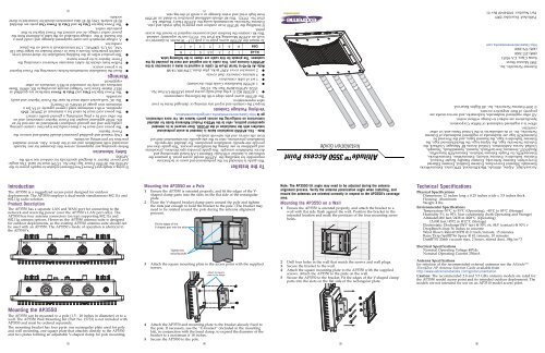
Altitude <strong>3550</strong> <strong>Access</strong> <strong>Point</strong><br />
Installation Guide<br />
To the Installer<br />
This guide is intended for the professional end users or technicians<br />
responsible for installing the AP<strong>3550</strong> model access point. It assumes the<br />
technician is familiar with basic Ethernet LAN-based networking and<br />
device installation concepts. This guide provides specifications, procedures<br />
and guidelines to use during the installation process. This guide does not<br />
provide site-specific installation procedures. For detailed site-specific<br />
installation procedures, refer to the site-specific documentation derived<br />
from site survey and site network analysis.<br />
Note - This AP<strong>3550</strong> Installation Guide is intended to assist professional<br />
installers with the installation of the AP<strong>3550</strong>. Once secured in its intended<br />
operational position, refer to the AP35xx Product Reference Guide for detailed<br />
instructions on configuring the access point’s feature set. For more information,<br />
go to http://www.extremenetworks.com/go/documentation.<br />
Verifying Package Contents<br />
Inspect the contents and report any missing or damaged items to your<br />
sales representative.<br />
The AP<strong>3550</strong> access point ships with the following components:<br />
● 1 AP<strong>3550</strong> 802.11 a+bg dual-radio access point (AP<strong>3550</strong>-US Part No.<br />
15722 AP<strong>3550</strong>-ROW Part No. 15726)<br />
● 1 AP<strong>3550</strong> Installation Guide (this document)<br />
● 1 set of cable connectors<br />
● 3 antenna connector dust covers<br />
● 2 connector cover AP67 jacks, plus chain_LTW-M9/14-SB<br />
Note: An RJ-45 to Serial (9-pin D) cable is required to make a connection to the<br />
AP<strong>3550</strong>’s Console port. This cable is not supplied and must be provided by the<br />
customer. The pinouts for this cable are shown in the following table.<br />
RJ-45 1 2 3 4,5 6 7 8<br />
DB9 8 6 2 5 3 4 7<br />
To mount the AP<strong>3550</strong> access point to a pole (1.5 - 18 inches in diameter) or<br />
wall, an AP<strong>3550</strong> Mounting Kit (Part No. 15733) can be separately ordered.<br />
This kit contains the brackets and accessories required to mount the access<br />
point.<br />
If installing the AP<strong>3550</strong> in an outdoor area prone to high winds and rain,<br />
<strong>Extreme</strong> <strong>Networks</strong> recommends using the AP<strong>3550</strong> Heavy Weather Kit<br />
(Part No. 15732). This kit affords additional protection to shield an AP<strong>3550</strong><br />
from high wind and water damage as a result of driving rain.<br />
(1)<br />
AP<strong>3550</strong>.<br />
Safety Information<br />
Before operating any equipment, review this document for any hazards<br />
associated with installation and use of the device. Also, review standard<br />
practices for preventing accidents.<br />
● Only trained and qualified personnel should install and remove the<br />
Power Injector.<br />
● The power cord must be a three-conductor type (two current carrying<br />
conductors and one ground conductor) terminated on one end by an<br />
IEC 60320 appliance coupler (for Power Injector connection) and on<br />
the other end by a plug containing a ground (earth) contact.<br />
● The power cord must be rated for a minimum of 250VAC RMS<br />
operation, with a minimum rated current capacity of 5A [or a<br />
minimum wire gauge of 18AWG (0.75mm²)].<br />
● The AC wall-socket outlet must be near the Power Injector and easily<br />
accessible.<br />
● The Power Injector Data and Data & Power interfaces are qualified as<br />
SELV (Safety Extra-Low Voltage) circuits according to IEC 60950. These<br />
interfaces can only be connected to SELV interfaces on other<br />
equipment.<br />
Warnings<br />
● Read the installation instructions before connecting the Power Injector<br />
to a power source.<br />
● Follow basic electricity safety measures whenever connecting the<br />
Power Injector to its power source.<br />
● This product relies on the building installation for short-circuit (over<br />
current) protection. Ensure a fuse or circuit breaker no larger than 120<br />
VAC, 3A U.S. (240VAC, 1.5A international) is used on the phase<br />
conductor.<br />
● A voltage mismatch can cause equipment damage and could pose a<br />
fire hazard. If the voltage indicated on the label is different from the<br />
power outlet voltage, do not connect the Power Injector to that<br />
particular outlet.<br />
● The Power Injector Data In and Data & Power Out ports are shielded<br />
RJ-45 sockets. Only RJ-45 data connectors should be connected to these<br />
sockets.<br />
port power injector is designed specifically for outdoor use with the<br />
AP<strong>3550</strong>, the AP<strong>3550</strong> Power Tap (Part No. 15729) must be used. This singleport<br />
If using a single-port Power-Over-Ethernet solution to supply power to the<br />
(2)<br />
Introduction<br />
The AP<strong>3550</strong> is a ruggedized access point designed for outdoor<br />
deployments. The AP<strong>3550</strong> employs a dual-mode simultaneous 802.11a and<br />
802.11g radio solution.<br />
Product Description<br />
The AP<strong>3550</strong> has a separate LAN and WAN port for connecting to the<br />
network and receiving power (over the AP<strong>3550</strong>’s LAN port only). The<br />
AP<strong>3550</strong> has four antenna connectors (on top) supporting 802.11a and<br />
802.11g antenna options. However, the AP<strong>3550</strong> antenna suite is designed<br />
for outdoor deployments, so the existing AP3510 antenna suite should not<br />
be used with an AP<strong>3550</strong>. The AP<strong>3550</strong>’s mode of operation is identical to<br />
the AP3510’s.<br />
Mounting the AP<strong>3550</strong> on a Pole<br />
1 Ensure the AP<strong>3550</strong> is oriented properly, and fit the edges of the V-<br />
shaped clamp parts into the slots on the flat side of the rectangular<br />
plate.<br />
2 Place the V-shaped bracket clamp parts around the pole and tighten<br />
the nuts just enough to hold the bracket to the pole. (The bracket may<br />
need to be rotated around the pole during the antenna alignment<br />
process).<br />
Fit the edges of the<br />
V-shaped part into the slots<br />
Note: The AP<strong>3550</strong> tilt angle may need to be adjusted during the antenna<br />
alignment process. Verify the antenna polarization angle when installing, and<br />
ensure the antennas are oriented correctly in respect to the AP<strong>3550</strong>'s coverage<br />
area.<br />
Mounting the AP<strong>3550</strong> on a Wall<br />
1 Ensure the AP<strong>3550</strong> is oriented properly, and attach the bracket to a<br />
wall with flat side flush against the wall. Position the bracket in the<br />
intended location and mark the positions of the four mounting screw<br />
holes.<br />
Technical Specifications<br />
Physical Specifications<br />
Dimensions 12 inches long x 8.25 inches wide x 3.5 inches thick<br />
Housing Aluminum<br />
Weight 4 lbs.<br />
Environmental Specifications<br />
Temperature-30°C to 55°C (Operating), -40°C to 85°C (Storage)<br />
Humidity 5% to 95% Non-condensing (both Operating and Storage)<br />
Altitude8,000 feet/2438 m @28°C (Operating)<br />
15,000 feet/4572 m @12°C (Storage)<br />
Electrostatic Discharge15kV (air) @ 50% rh, 8kV (contact) @ 50% r<br />
DropBench drop 36 inches to concrete<br />
Wind Blown Rain40 MPH @ 0.1inch/minute, 15 minutes<br />
Rain/Drip/SpillIPX6 Spray @ 4L/minute, 10 minutes<br />
DustIP5X 20mb vacuum max, 2 hours, stirred dust, .88g/m^3<br />
Tighten the<br />
securing bolts<br />
Electrical Specifications<br />
Nominal Operating Voltage 48Vdc<br />
Nominal Operating Current 250mA<br />
3 Attach the square mounting plate to the access point with the supplied<br />
screws.<br />
<br />
<br />
2 Drill four holes in the wall that match the screws and wall plugs.<br />
3 Secure the bracket to the wall.<br />
4 Attach the square mounting plate to the AP<strong>3550</strong> with the supplied<br />
screws. Attach the AP<strong>3550</strong> to the plate on the wall.<br />
5 Secure the AP<strong>3550</strong> to the bracket. Fit the edges of the V-shaped clamp<br />
parts into the slots on the flat side of the rectangular plate.<br />
Antenna Specifications<br />
for selection of the recommended external antennas see the Altitude<br />
35xx/45xx AP Antenna Selection Guide available from<br />
http://www.extremenetworks.com/go/documentation<br />
Caution: The recommended 2.4 and 5.5 GHz antenna models are rated for<br />
the AP<strong>3550</strong> model access point and its intended outdoor deployment. The<br />
models are not intended for use on an AP3510 model access point.<br />
Mounting the AP<strong>3550</strong><br />
The AP<strong>3550</strong> can be mounted to a pole (1.5 - 18 inches in diameter) or to a<br />
wall. The AP<strong>3550</strong> Wall Mounting Kit (Part No. 15733) is not included with<br />
AP<strong>3550</strong> and must be ordered separately.<br />
The mounting bracket has four parts: one rectangular plate used for pole<br />
and wall mounting, one square plate that attaches directly to the AP<strong>3550</strong><br />
and two plates forming an adjustable V-shaped clamp for pole mounting.<br />
4 Attach the AP<strong>3550</strong> and mounting plate to the bracket already fixed to<br />
the pole. If necessary, use the “U-bracket” (included in the mounting<br />
kit), in conjunction with the band clamp, to expand the diameter of the<br />
bracket to a maximum if 18 inches.<br />
5 Secure the AP<strong>3550</strong> to the pole.<br />
(3) (4) (5) (6)
AP<strong>3550</strong> LEDs<br />
The AP<strong>3550</strong> access point has four LEDs matching the functionality of the<br />
AP3510 model access point. However, the AP<strong>3550</strong>’s LEDs are on the<br />
bottom of the access point.<br />
Power and error conditions (split LED)<br />
Data over Ethernet<br />
802.11a radio activity<br />
802.11b/g radio activity<br />
The AP<strong>3550</strong>’s LEDs have the following display and functionality:<br />
● Power Status - Solid white indicates the AP<strong>3550</strong> is adequately powered.<br />
● Error Conditions - Solid red indicates the AP<strong>3550</strong> has a problem<br />
requiring attention.<br />
● Ethernet Activity - Flashing white indicates data transfers and Ethernet<br />
activity.<br />
● 802.11a Activity - Flickering amber indicates beacons and data transfers<br />
over the radio.<br />
● 802.11b/g Activity - Flickering green indicates beacons and data<br />
transfers over the radio.<br />
sy<br />
<strong>Extreme</strong> <strong>Networks</strong> Technical Assistance Centers (TAC) provide 24x7x365<br />
worldwide coverage. These centers are the focal point of contact for postsales<br />
technical and network-related questions or issues. TAC will create a<br />
Service Request (SR) number and manage all aspects of the SR until it is<br />
resolved. For a complete guide to customer support, see the Technical<br />
Assistance Center User Guide at:<br />
http://www.extremenetworks.com/go/TACUserGuide<br />
The <strong>Extreme</strong> <strong>Networks</strong> eSupport website provides the latest information<br />
on <strong>Extreme</strong> <strong>Networks</strong> products, including the latest Release Notes,<br />
troubleshooting, downloadable updates or patches as appropriate, and<br />
other useful information and resources. Directions for contacting the<br />
<strong>Extreme</strong> <strong>Networks</strong> Technical Assistance Centers are also available from the<br />
eSupport website at:<br />
https://esupport.extremenetworks.com<br />
Registration<br />
If you have not already registered with <strong>Extreme</strong> <strong>Networks</strong> using a<br />
registration card supplied with your product, you can register on the<br />
<strong>Extreme</strong> <strong>Networks</strong> website at:<br />
http://www.extremenetworks.com/go/productregistration.<br />
Documentation<br />
Check for the latest versions of documentation on the <strong>Extreme</strong> <strong>Networks</strong><br />
documentation website at:<br />
http://www.extremenetworks.com/go/documentation<br />
Regulatory Information<br />
All <strong>Extreme</strong> <strong>Networks</strong> devices are designed to be compliant with rules and<br />
regulations in locations of intended sale and are labeled as required by the<br />
authorizing agency. Any changes or modifications to <strong>Extreme</strong> <strong>Networks</strong><br />
equipment, not expressly approved by <strong>Extreme</strong> <strong>Networks</strong>, could void the<br />
user's authority to operate the equipment.<br />
When <strong>Extreme</strong> <strong>Networks</strong> devices are professionally installed the Radio<br />
Frequency Output Power will not exceed the maximum allowable limit for<br />
the country of operation when properly installed.<br />
Antennas: Use only the supplied or an approved replacement antenna.<br />
Unauthorized antennas, modifications, or attachments could cause damage<br />
and may violate regulations.<br />
Power Supply<br />
The AP<strong>3550</strong> access point receives power via an Ethernet cable connected to<br />
the RJ45 LAN port (using unused pairs). <strong>Extreme</strong> <strong>Networks</strong> recommends the<br />
model 15729 Power Tap-Altitude <strong>3550</strong> to be used to provide power to the<br />
AP<strong>3550</strong> access point. The Power Tap is a ruggedized solution designed for<br />
outdoor deployments. It is pre-approved for use with the AP<strong>3550</strong> and is<br />
compliant with several international safety, EMC and Environmental<br />
standards. Refer to http://www.extremenetworks.com/go/rfcertification/htm for<br />
approved country list.<br />
Caution - Use only an <strong>Extreme</strong> <strong>Networks</strong> approved power supply. Use of an<br />
alternative power supply may invalidate any approval given to this device and<br />
may be dangerous if not properly tested and approved by local agency.<br />
Wireless Devices - Countries<br />
Country Selection. The <strong>Extreme</strong> <strong>Networks</strong> AP<strong>3550</strong> <strong>Access</strong> <strong>Point</strong> is<br />
manufactured as 2 model numbers. The location of installation will determine<br />
the appropriate model number to choose. Due to unique regulatory<br />
requirements within the United States only the United States will appear in<br />
the country list upon initial set up. The AP<strong>3550</strong>-ROW 11abg will list many<br />
countries where it is the professional installer and end users responsibility to<br />
properly pick the correct country of use and set up the AP in accordance with<br />
all instructions provided.<br />
● 15722 AP<strong>3550</strong>-US 11abg AP (For use in US only)<br />
● 15726 AP<strong>3550</strong>-ROW 11abg AP (For use in Europe & Rest of World)<br />
The outdoor use of an 802.11abg access point may be allowed but it does<br />
have frequency restrictions and may require a license for operation. Please<br />
refer to all instructions to properly set up this AP to ensure proper use.<br />
Contact local country Authority for procedure to follow and regulatory<br />
information. For details on approved countries please visit<br />
http://www.extremenetworks.com/go/rfcertification.htm or contact <strong>Extreme</strong><br />
<strong>Networks</strong>.<br />
Warning: - Select only the country in which you are using the device. Any<br />
other selection will make the operation of this device illegal. The professional<br />
installer and end user are responsible to properly follow all instructions and<br />
warning when installing this device.<br />
United States<br />
The <strong>Extreme</strong> <strong>Networks</strong> 15722 AP<strong>3550</strong>-US <strong>Access</strong> <strong>Point</strong> is dedicated for use in<br />
the United States under rules of the FCC. Other countries may use the model<br />
if they agree with FCC operating frequencies and powers applicable to this<br />
model.<br />
The use on UNII (Unlicensed National Information Infrastructure) Band 1<br />
To reduce potential radio interference to other users, the antenna type and<br />
its gain should be so chosen that the equivalent isotropically radiated<br />
power (EIRP) is not more than that permitted for successful<br />
communication.<br />
This device has been designed to operate with the antennas listed in the<br />
Altitude 35xx/45xx AP Antenna Selection Guide available from<br />
http://www.extremenetworks.com/go/documentation, and have a maximum<br />
gain of 9dBi (2.4GHz) and 10dBi (5GHz). Antennas not included in this<br />
guide, or having a gain greater than 9dBi (2.4GHz) and 10dBi (5GHz) are<br />
strictly prohibited for use with this device. The required antenna<br />
impedance is 50 ohms.<br />
Label Marking: The Term "IC:" before the radio certification signifies that<br />
Industry Canada technical specifications were met.<br />
European Economic Area (EEA)<br />
CE Marking. The Altitude model AP<strong>3550</strong>-ROW 11abg AP is uniquely<br />
designed for use in the European Union and other countries with similar<br />
regulatory restrictions where the end user or installer is allowed to<br />
configure the Altitude AP for operation by selecting a specific country<br />
from a list of countries. Upon connection to the controller, software will<br />
prompt the user to select a country. After the country is selected, the<br />
controller will set up the Altitude AP with the proper frequencies and<br />
power outputs for that country as required by authorities. It is the<br />
professional user or installer’s responsibility to ensure the proper set up of<br />
the AP to correct channel limitations, indoor/outdoor restrictions, license<br />
requirements, and operation within power level limits for the country of<br />
intended operation in accordance with the spectrum usage rules for<br />
compliance with the European R&TTE directive 1999/5/EC.<br />
The outdoor use of an 802.11abg access point is allowed in EU but does<br />
have frequency restrictions and may require a license for operation. Please<br />
refer to all instructions to properly set up this AP to ensure proper use in<br />
accordance with all European spectrum usage rules. Contact local country<br />
Authority for procedure to follow and regulatory information. For details<br />
on approved countries please visit http://www.extremenetworks.com/go/<br />
rfcertification.htm or contact <strong>Extreme</strong> <strong>Networks</strong>.<br />
The use of 2.4GHz RLAN’s, for use throughout the EEA, includes the<br />
following countries have the following restrictions:<br />
Europe includes, Austria, Belgium, Bulgaria, Czech Republic, Cyprus,<br />
Denmark, Estonia, Finland, France, Germany, Greece, Hungary, Iceland,<br />
Ireland, Italy, Latvia, Liechtenstein, Lithuania, Luxembourg, Malta,<br />
Netherlands, Norway, Poland, Portugal, Romania, Slovak Republic,<br />
Slovenia, Spain, Sweden, Switzerland and the United Kingdom.<br />
5150-5250 MHz is restricted to indoor use only, any other use will make the<br />
(7) (9) (11) (13)<br />
Note: When starting the access point in cold weather (below -30°C), there might<br />
not be any LED indicator activity, even though the access point may be<br />
receiving power.<br />
Powering the <strong>Access</strong> <strong>Point</strong><br />
An AP<strong>3550</strong> model access point receives power via an Ethernet cable<br />
connected to the AP<strong>3550</strong>’s LAN port (using unused pairs).<br />
When users purchase an <strong>Extreme</strong> <strong>Networks</strong> WLAN solution, they often<br />
need to place access points in obscure locations. In the past, a dedicated<br />
power source was required for each access point in addition to the Ethernet<br />
infrastructure. This often required an electrical contractor to install power<br />
drops at each access point location. An approved solution merges power<br />
and Ethernet into one cable, reducing the burden of installation and allows<br />
optimal access point placement in respect to the intended radio coverage<br />
area.<br />
The AP<strong>3550</strong> model access point is powered using the <strong>Extreme</strong> <strong>Networks</strong><br />
Power Tap (Part No. 15729). The Power Tap is a ruggedized solution<br />
designed for outdoor deployments. The Power Tap may be deployed<br />
outdoors at the access point location, or deployed indoors to inject power<br />
over the Ethernet cable to an AP<strong>3550</strong> located outdoors.<br />
A Power Tap receives power and is ready for AP<strong>3550</strong> connection and<br />
operation as soon as AC power is applied. There is no On/Off switch.<br />
Caution - The AP<strong>3550</strong> accepts Power over Ethernet only on un-used pairs.<br />
Using the wrong power solution (including a non-compliant POE system or a<br />
solution not rated for outdoor use) could severely damage the AP<strong>3550</strong> and<br />
void the product warranty.<br />
Caution - For Power Tap installations, an electrician is required to open the<br />
unit, feed the power cable through the Line AC connector, secure the power<br />
cable to the unit’s three screw termination block and tighten the unit’s Line<br />
AC clamp (by hand) to secure the power cable. Only a certified electrician<br />
should conduct the installation. Additionally, an electrician must attach a<br />
ground cable between the EARTH GROUND connector (on the back of the<br />
unit) to a suitable earth ground connection as defined by your local<br />
electrical code.<br />
Customer Support<br />
Note - Services can be purchased from <strong>Extreme</strong> <strong>Networks</strong> or through one of its<br />
channel partners. If you are an end-user who has purchased service through an<br />
<strong>Extreme</strong> <strong>Networks</strong> channel partner, please contact your partner first for support.<br />
Country Approvals<br />
Regulatory markings & ID# have been applied to the device product label<br />
signifying the radio (s) are approved for use in the country list located at<br />
http://www.extremenetworks.com/go/rfcertification.htm. This list of countries is<br />
extensive and includes but is not limited to United States, Canada, Australia,<br />
Japan, Europe and China. Operation of the device without appropriate<br />
regulatory approvals is illegal.<br />
Health and Safety Recommendations<br />
Warnings for the use of Wireless Devices<br />
Please observe all warning notices with regard to the usage of<br />
wireless devices.<br />
Potentially Hazardous Atmospheres<br />
You are reminded to observe restrictions on the use of radio devices in fuel<br />
depots, chemical plants etc. and areas where the air contains chemicals or<br />
particles (such as grain, dust, or metal powders) and any other area where<br />
you would normally be advised to turn off your vehicle engine.<br />
Safety in Hospitals<br />
Wireless devices transmit radio frequency energy and may affect<br />
medical electrical equipment. When installed adjacent to other<br />
equipment, it is advised to verify that the adjacent equipment is not<br />
adversely affected.<br />
FCC / EU RF Exposure Guidelines<br />
Safety Information. The device complies with internationally recognized<br />
standards covering human exposure to electromagnetic fields from radio<br />
devices.<br />
Reducing RF Exposure—Use Properly. It is advisable to use the device only in<br />
the normal operating position as described in this guide.<br />
operation of this device illegal. The AP<strong>3550</strong> is not DF2 compliant and is for<br />
outdoor use. Therefore, it only operates using 5.725-5.8250 (Channels 149-165)<br />
The available channels for 802.11 b/g operation in the US are Channels 1 to<br />
11. The range of channels is limited by firmware.<br />
FCC - Radio Frequency Interference Statement<br />
This equipment has been tested and found to comply with the limits for a<br />
Class B digital device, pursuant to Part 15 of the FCC rules. These limits are<br />
designed to provide reasonable protection against harmful interference in a<br />
residential installation. This equipment generates, uses<br />
and can radiate radio frequency energy and, if not<br />
installed and used in accordance with the instructions,<br />
may cause harmful interference to radio communications.<br />
However there is no guarantee that interference will not<br />
occur in a particular installation. If this equipment does<br />
cause harmful interference to radio or television reception, which can be<br />
determined by turning the equipment off and on, the user is encouraged to<br />
try to correct the interference by one or more of the following measures:<br />
● Reorient or relocate the receiving antenna<br />
● Increase the separation between the equipment and receiver<br />
● Connect the equipment into an outlet on a circuit different from that to<br />
which the receiver is connected<br />
● Consult the dealer or an experienced radio/TV technician for help.<br />
Radio Transmitters (Part 15). This device complies with Part 15 of the FCC<br />
Rules. Operation is subject to the following two conditions: (1) this device<br />
may not cause harmful interference, and (2) this device must accept any<br />
interference received, including interference that may cause undesired<br />
operation.<br />
Canada<br />
IC - Radio Frequency Interference Statement<br />
This Class B digital apparatus complies with Canadian ICES-003.<br />
Cet appareil numérique de la classe B est conforme à la norme NMB-003 du<br />
Canada.<br />
● Maximum radiated transmit power of 100 mW EIRP in the frequency<br />
range 2.400 -2.4835 GHz. (Channels 1-13).<br />
● 5GHz operation is limited to 5.15 to 5.25 GHz (Channels 36 40, 44 &<br />
48) indoor use only. The AP<strong>3550</strong> does not support ETSI 301 893 V 1.3.1<br />
therefore 5GHz operation is not allowed for outside applications<br />
● Antenna use is restricted to those antennas listed in Altitude 35xx/<br />
45xx AP Antenna Selection Guide See http://www.extremenetworks.com/<br />
go/documentation for details.<br />
● France outside usage, the equipment is restricted to 2.400-2.45 GHz<br />
frequency range. Channels 1 - 7.<br />
● Italy & Greece requires a user license for outside usage.<br />
● Belgium requires notifying the spectrum agency if deploying > 300<br />
meter wireless links in outdoor public areas and outdoor operation is<br />
only permitted using the 2.46 - 2.4835 GHz band: Channel 13.<br />
● The Altitude APs require the end user or installer to ensure that a valid<br />
license is obtained prior to operating the Altitude AP. The license<br />
contains the region and any restrictions or configuration limitations<br />
required for proper operation in conformance with European National<br />
spectrum usage laws.<br />
Statement of Compliance. <strong>Extreme</strong> <strong>Networks</strong> hereby, declares that this<br />
device is in compliance with the essential requirements and<br />
other relevant provisions of Directive 1999/5/EC. For a copy<br />
of Declaration of Conformity (DoC) and additional declarations<br />
in country languages and warnings please visit<br />
http://www.extremenetworks.com/go/rfcertification.htm.<br />
Note - The Altitude AP<strong>3550</strong> is in compliance with the European Directive 2002/<br />
95/EC on the restriction of the use of certain hazardous substances (RoHS) in<br />
electrical and electronic equipment and the European Directive 2002/96/EC<br />
(WEEE) on waste electrical and electronic equipment.<br />
RF safety distance. This access point must be installed to provide a<br />
separation distance of at least 25cm from all persons and must not be<br />
co-located or operating in conjunction with another antenna or transmitter.<br />
Radio Transmitters. This device complies with RSS 210 of Industry & Science<br />
Remote and Standalone Antenna Configurations. To comply with FCC RF<br />
Canada. Operation is subject to the following two conditions: (1) this device<br />
exposure requirements, antennas that are mounted externally at remote<br />
may not cause harmful interference and (2) this device must accept any<br />
locations or operating near users at stand-alone desktop of similar<br />
interference received, including interference that may cause undesired<br />
configurations must operate with a minimum separation distance of 20 cm<br />
operation.<br />
from all persons.<br />
(8) (10) (12) (14)


