Design and Implementation of NOC Based 16 PE
Design and Implementation of NOC Based 16 PE
Design and Implementation of NOC Based 16 PE

You also want an ePaper? Increase the reach of your titles
YUMPU automatically turns print PDFs into web optimized ePapers that Google loves.
<strong>Design</strong> <strong>and</strong> <strong>Implementation</strong> <strong>of</strong> <strong>NOC</strong> <strong>Based</strong> <strong>16</strong> <strong>PE</strong><br />
O.Hammami, , K.Hamwi, M.H.Jabbar,M.Khaddour,A.Mzah<br />
ENSTA Paristech,<br />
75739, Paris, France<br />
hammami@ensta.fr<br />
Abstract— Multiprocessor system on chip is now emerging in<br />
many embedded system applications. With the transistor<br />
technology continue to be smaller in geometry, integration <strong>of</strong><br />
large number <strong>of</strong> processors <strong>and</strong> other components is possible.<br />
However, communication has become crucial as the number <strong>of</strong><br />
processors <strong>and</strong> IP blocks is increased in the MPSoC architecture.<br />
Network on Chip (NoC) is an alternative to bus based<br />
communication approach which provides superior advantages.<br />
In this paper, we designed <strong>and</strong> implemented NoC-based MPSoC<br />
design on Xilinx Virtex 4 LX200 FPGA. Two NoC architecture;<br />
2-ary 4-tree <strong>and</strong> 2-ary 4-fly, is developed to be used for the<br />
MPSoC communication.<br />
Keywords— MPSoC, NoC, FPGA.<br />
The netlist is converted to EDF files to be used by ZeBu<br />
Compiler. In ZeBu compiler, several threads are performed in<br />
parallel for synthesis, place <strong>and</strong> route process on the target<br />
board. S<strong>of</strong>tware application is developed at this point in the<br />
Xilinx EDK tool using C programming.<br />
Xilinx IP<br />
Library<br />
Processors,<br />
BRAMs<br />
MHS File<br />
Xilinx EDK<br />
NoC Architecture<br />
PDD File<br />
Arteris<br />
NoCcompiler<br />
Arteris<br />
Danube IP<br />
Library<br />
I. INTRODUCTION<br />
The aim <strong>of</strong> this work is to demonstrated MPSoC design<br />
with <strong>16</strong> MicroBlazes as master <strong>and</strong> <strong>16</strong> SSRAMs as slave. The<br />
masters <strong>and</strong> slaves are connected through 2-ary 4-tree <strong>and</strong> 2-<br />
ary 4-fly NoC architecture. It is chosen due to the similar<br />
properties in terms <strong>of</strong> the number <strong>of</strong> master <strong>and</strong> slave such<br />
that fair comparison can be made. Several interfaces have<br />
been designed to accommodate different communication<br />
st<strong>and</strong>ard between MicroBlaze <strong>and</strong> SSRAM with the NoC.<br />
Additional Application Programming Interface (APIs) is also<br />
developed used for synchronization <strong>of</strong> the masters.<br />
II. DESIGN FLOW<br />
Xilinx Platgen<br />
RTL File (vhdl)<br />
RTL File (vhdl)<br />
Xilinx XST <strong>and</strong><br />
ngc2edf<br />
EDF Files<br />
Zebu Compiler<br />
(zCui)<br />
SW Applications<br />
EDK<br />
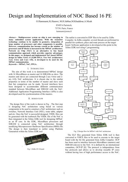
The design flow <strong>of</strong> the work is shown in Fig. . The first step<br />
is designing NoC architecture using based on various<br />
components to be used to construct a NoC architecture such as<br />
switches, Network Interface Unit (NIU), route table, adapter<br />
<strong>and</strong> etc. Once the NoC is successful designed, VHDL files can<br />
be generated with the testbench.The VHDL file <strong>of</strong> the NoC is<br />
then integrated in the Xilinx EDK tool for designing MPSoC<br />
as an IP core. In the EDK, MicroBlaze processors <strong>and</strong><br />
SSRAM is connected using NoC architecture through<br />
modifying Microprocessor Hardware Specification (MHS) file.<br />
The design is then translated to netlist using Platform<br />
Generation within the Xilinx EDK tool<br />
.<br />
Fig. 1 ZeBu UF-4 board<br />
Xilinx PAR<br />
(thread 1)<br />
. . .<br />
Bit File<br />
Xilinx PAR<br />
(thread N)<br />
Execution<br />
ELF Files<br />
VHEX Files<br />
Fig. 2 <strong>Design</strong> flow for MPSoC with NoC architecture<br />
Report Files<br />
The ELF files generated from Xilinx EDK tool is then<br />
converted to VHEX files to be used to execute to the target<br />
board with the bit file generated from ZeBu Compiler. OCP<br />
has been used to interface between MicroBlaze (masters) <strong>and</strong><br />
SSRAM (slaves) to the NoC. It is defined by an international<br />
committee, OCP-IP [8]. The protocol is independence from<br />
bus protocols <strong>and</strong> allows us to develop reusable IP cores<br />
without having loss <strong>of</strong> high performance access to the NoC.<br />
1
The OCP protocol uses 32 bit data width for masters as well<br />
as slave connection.<br />
ZeBu UF-4 board as shown in Fig. has 4 FPGA devices based<br />
on Xilinx Virtex-4 LX200 that is equivalent <strong>of</strong> 6 million <strong>of</strong><br />
ASIC gates on a single PCI card [9].<br />
The structure <strong>of</strong> MPSoC is shown in Fig.3 for the design with<br />
2-ary 4-tree <strong>and</strong> 2-ary 4-fly NoC architecture respectively. All<br />
the MPSoC have been realized using Embedded <strong>Design</strong> Kit<br />
(EDK) tools from Xilinx [10]. MicroBlaze s<strong>of</strong>tcore processor,<br />
as shown in Figure 5, is used as masters <strong>and</strong> SSRAM is used<br />
as slaves for all MPSoC designs. The MicroBlaze is an<br />
embedded s<strong>of</strong>t core processors from Xilinx based on 32 bits<br />
Reduced Instruction Set Computer (RISC). It is highly<br />
reconfigurable <strong>and</strong> <strong>of</strong>fer design flexibility in which users can<br />
select several configuration options such as floating point<br />
Microblaze 0<br />
Microblaze 1<br />
FSL-to-OCP<br />
interface<br />
FSL-to-OCP<br />
interface<br />
OCP-to-NTTP<br />
interface<br />
OCP-to-NTTP<br />
interface<br />
0.0<br />
1.0<br />
2.0<br />
Network-on-chip<br />
3.0<br />
4.0<br />
5.0<br />
6.0<br />
NTTP-to-OCP<br />
interface<br />
NTTP-to-OCP<br />
interface<br />
OCP-to-BRAM<br />
interface<br />
OCP-to-BRAM<br />
interface<br />
SRAM 0<br />
SRAM 1<br />
units, integer multiplier <strong>and</strong> integer divider. The MicroBlaze<br />
processor is configured to its full configuration <strong>and</strong> is given<br />
additional local 32 kB Block R<strong>and</strong>om Access Memory<br />
(BRAM) memory connected via two LMB BRAM Memory<br />
Controllers using 2 LMBs (Local Memory Bus) to provide<br />
Instruction Memory (via ILMB port) <strong>and</strong> Data Memory (via<br />
DLMB port). The MicroBlaze uses Fast Simplex Link (FSL)<br />
for its interconnection. FSL bus is a uni-directional connection,<br />
provides simple <strong>and</strong> fast point-to-point communication<br />
between two components in the EDK environment. Off chip<br />
memory is used for the slave due to the large size is needed to<br />
stored the data block. Using SRAM from the ZeBu UF4 board,<br />
each slave has the value <strong>of</strong> 2 MB.<br />
FSL-to-OCP OCP-to-NTTP<br />
NTTP-to-OCP OCP-to-BRAM<br />
Microblaze 0 Network -on-chip<br />
SRAM 0<br />
interface<br />
interface<br />
interface<br />
interface<br />
0.0<br />
1.0<br />
2.0<br />
3.0<br />
FSL-to-OCP OCP-to-NTTP<br />
NTTP-to-OCP OCP-to-BRAM<br />
Microblaze 1<br />
interface<br />
interface<br />
interface<br />
interface<br />
SRAM 1<br />
Microblaze 2<br />
FSL-to-OCP<br />
interface<br />
OCP-to-NTTP<br />
interface<br />
NTTP-to-OCP<br />
interface<br />
OCP-to-BRAM<br />
interface<br />
SRAM 2<br />
Microblaze 2<br />
Microblaze 3<br />
FSL-to-OCP<br />
interface<br />
FSL-to-OCP<br />
interface<br />
OCP-to-NTTP<br />
interface<br />
OCP-to-NTTP<br />
interface<br />
0.1<br />
1.1<br />
2.1<br />
3.1<br />
4.1<br />
5.1<br />
6.1<br />
NTTP-to-OCP<br />
interface<br />
NTTP-to-OCP<br />
interface<br />
OCP-to-BRAM<br />
interface<br />
OCP-to-BRAM<br />
interface<br />
SRAM 2<br />
SRAM 3<br />
Microblaze 3<br />
Microblaze 4<br />
FSL-to-OCP<br />
interface<br />
FSL-to-OCP<br />
interface<br />
OCP-to-NTTP<br />
interface<br />
OCP-to-NTTP<br />
interface<br />
0.1<br />
1.1<br />
2.1<br />
3.1<br />
NTTP-to-OCP<br />
interface<br />
NTTP-to-OCP<br />
interface<br />
OCP-to-BRAM<br />
interface<br />
OCP-to-BRAM<br />
interface<br />
SRAM 3<br />
SRAM 4<br />
Microblaze 4<br />
Microblaze 5<br />
FSL-to-OCP<br />
interface<br />
FSL-to-OCP<br />
interface<br />
OCP-to-NTTP<br />
interface<br />
OCP-to-NTTP<br />
interface<br />
0.2<br />
1.2<br />
2.2<br />
3.2<br />
4.2<br />
5.2<br />
6.2<br />
NTTP-to-OCP<br />
interface<br />
NTTP-to-OCP<br />
interface<br />
OCP-to-BRAM<br />
interface<br />
OCP-to-BRAM<br />
interface<br />
SRAM 4<br />
SRAM 5<br />
Microblaze 5<br />
Microblaze 6<br />
FSL-to-OCP<br />
interface<br />
FSL-to-OCP<br />
interface<br />
OCP-to-NTTP<br />
interface<br />
OCP-to-NTTP<br />
interface<br />
0.2<br />
1.2<br />
2.2<br />
3.2<br />
NTTP-to-OCP<br />
interface<br />
NTTP-to-OCP<br />
interface<br />
OCP-to-BRAM<br />
interface<br />
OCP-to-BRAM<br />
interface<br />
SRAM 5<br />
SRAM 6<br />
Microblaze 6<br />
Microblaze 7<br />
FSL-to-OCP<br />
interface<br />
FSL-to-OCP<br />
interface<br />
OCP-to-NTTP<br />
interface<br />
OCP-to-NTTP<br />
interface<br />
0.3<br />
1.3<br />
2.3<br />
3.3<br />
4.3<br />
5.3<br />
6.3<br />
NTTP-to-OCP<br />
interface<br />
NTTP-to-OCP<br />
interface<br />
OCP-to-BRAM<br />
interface<br />
OCP-to-BRAM<br />
interface<br />
SRAM 6<br />
SRAM7<br />
Microblaze 7<br />
FSL-to-OCP<br />
interface<br />
OCP-to-NTTP<br />
interface<br />
0.3<br />
1.3<br />
2.3<br />
3.3<br />
NTTP-to-OCP<br />
interface<br />
OCP-to-BRAM<br />
interface<br />
SRAM 7<br />
Microblaze 8<br />
Microblaze 9<br />
FSL-to-OCP<br />
interface<br />
FSL-to-OCP<br />
interface<br />
OCP-to-NTTP<br />
interface<br />
OCP-to-NTTP<br />
interface<br />
0.4<br />
1.4<br />
2.4<br />
3.4<br />
4.4<br />
5.4<br />
6.4<br />
NTTP-to-OCP<br />
interface<br />
NTTP-to-OCP<br />
interface<br />
OCP-to-BRAM<br />
interface<br />
OCP-to-BRAM<br />
interface<br />
SRAM 8<br />
SRAM 9<br />
Microblaze 8<br />
Microblaze 9<br />
FSL-to-OCP<br />
interface<br />
FSL-to-OCP<br />
interface<br />
OCP-to-NTTP<br />
interface<br />
OCP-to-NTTP<br />
interface<br />
0.4<br />
1.4<br />
2.4<br />
3.4<br />
NTTP-to-OCP<br />
interface<br />
NTTP-to-OCP<br />
interface<br />
OCP-to-BRAM<br />
interface<br />
OCP-to-BRAM<br />
interface<br />
SRAM 8<br />
SRAM 9<br />
Microblaze 10<br />
Microblaze 11<br />
FSL-to-OCP<br />
interface<br />
FSL-to-OCP<br />
interface<br />
OCP-to-NTTP<br />
interface<br />
OCP-to-NTTP<br />
interface<br />
0.5<br />
1.5<br />
2.5<br />
3.5<br />
4.5<br />
5.5<br />
6.5<br />
NTTP-to-OCP<br />
interface<br />
NTTP-to-OCP<br />
interface<br />
OCP-to-BRAM<br />
interface<br />
OCP-to-BRAM<br />
interface<br />
SRAM 10<br />
SRAM 11<br />
Microblaze 10<br />
Microblaze 11<br />
FSL-to-OCP<br />
interface<br />
FSL-to-OCP<br />
interface<br />
OCP-to-NTTP<br />
interface<br />
OCP-to-NTTP<br />
interface<br />
0.5<br />
1.5<br />
2.5<br />
3.5<br />
NTTP-to-OCP<br />
interface<br />
NTTP-to-OCP<br />
interface<br />
OCP-to-BRAM<br />
interface<br />
OCP-to-BRAM<br />
interface<br />
SRAM 10<br />
SRAM 11<br />
Microblaze 12<br />
Microblaze 13<br />
FSL-to-OCP<br />
interface<br />
FSL-to-OCP<br />
interface<br />
OCP-to-NTTP<br />
interface<br />
OCP-to-NTTP<br />
interface<br />
0.6<br />
1.6<br />
2.6<br />
3.6<br />
4.6<br />
5.6<br />
6.6<br />
NTTP-to-OCP<br />
interface<br />
NTTP-to-OCP<br />
interface<br />
OCP-to-BRAM<br />
interface<br />
OCP-to-BRAM<br />
interface<br />
SRAM 12<br />
SRAM 13<br />
Microblaze 12<br />
Microblaze 13<br />
FSL-to-OCP<br />
interface<br />
FSL-to-OCP<br />
interface<br />
OCP-to-NTTP<br />
interface<br />
OCP-to-NTTP<br />
interface<br />
0.6<br />
1.6<br />
2.6<br />
3.6<br />
NTTP-to-OCP<br />
interface<br />
NTTP-to-OCP<br />
interface<br />
OCP-to-BRAM<br />
interface<br />
OCP-to-BRAM<br />
interface<br />
SRAM 12<br />
SRAM 13<br />
Microblaze 14<br />
Microblaze 15<br />
FSL-to-OCP<br />
interface<br />
FSL-to-OCP<br />
interface<br />
OCP-to-NTTP<br />
interface<br />
OCP-to-NTTP<br />
interface<br />
0.7<br />
1.7<br />
2.7<br />
3.7<br />
4.7<br />
5.7<br />
6.7<br />
NTTP-to-OCP<br />
interface<br />
NTTP-to-OCP<br />
interface<br />
OCP-to-BRAM<br />
interface<br />
OCP-to-BRAM<br />
interface<br />
SRAM 14<br />
SRAM 15<br />
Microblaze 14<br />
Microblaze 15<br />
FSL-to-OCP<br />
interface<br />
FSL-to-OCP<br />
interface<br />
OCP-to-NTTP<br />
interface<br />
OCP-to-NTTP<br />
interface<br />
0.7<br />
1.7<br />
2.7<br />
3.7<br />
NTTP-to-OCP<br />
interface<br />
NTTP-to-OCP<br />
interface<br />
OCP-to-BRAM<br />
interface<br />
OCP-to-BRAM<br />
interface<br />
SRAM 14<br />
SRAM 15<br />
III. EX<strong>PE</strong>RIMENTAL RESULTS<br />
TABLE I compares the FPGA resources <strong>of</strong> the two NoC<br />
architectures in the MPSoC design. 2-ary 4-tree architecture<br />
has more slices than 2-ary 4-fly NoC for about 2% because it<br />
contains more switches. For BRAM <strong>and</strong> DSP48, both NoC<br />
IV. CONCLUSION<br />
In this paper, we discussed the design <strong>and</strong> implementation<br />
on FPGA <strong>of</strong> MPSoC with NoC architecture. Two MPSoC<br />
designs with different NoC architecture have been executed<br />
on Virtex 4 LX200 FPGA from Xilinx. The design is<br />
evaluated using parallel programming DCT algorithm. Result<br />
shown that for DCT application on 2-ary 4-fly NoC<br />
architecture has slightly better speedup 2-ary 4-fly NoC<br />
architecture. In terms <strong>of</strong> logic utilization, MPSoC design with<br />
2-ary 4-fly used more 2% <strong>of</strong> slices than 2-ary 4-fly NoC<br />
architecture.<br />
Fig. 1 Block diagram <strong>of</strong> MPSoC with 2-ary 4-fly NoC architecture<br />
TABLE I<br />
LOGIC UTILIZATION OF MPSOC WITH DIFFERENT <strong>NOC</strong> ARCHITECTURE<br />
NoC Topology Slices % BRAM % DSP %<br />
2-ary 4-tree 40.73 76.49 50<br />
2-ary 4-fly 38.00 76.49 50<br />
architectures have the same value which is 76% <strong>and</strong> 50%<br />
respectively. These values are come from the MPSoC design<br />
such as MicroBlaze processors <strong>and</strong> other IPs such as OCP<br />
interfaces.<br />
[1] W. Wolf, A. A. Jerraya, <strong>and</strong> G. Martin, "Multiprocessor System-on-<br />
Chip (MPSoC) Technology," Computer-Aided <strong>Design</strong> <strong>of</strong> Integrated<br />
Circuits <strong>and</strong> Systems, IEEE Transactions on, vol. 27, pp. 1701-1713,<br />
2008.<br />
[2] OCP-IP, www.ocpip.org.<br />
[3] EVE, "ZeBu UF-4," http://www.eve-team.com.<br />
[4] Xilinx, www.xilinx.com.<br />
REFERENCES<br />
2