100 Fundamentals for the Do-it-yourself Owner - Saab 900 ...
100 Fundamentals for the Do-it-yourself Owner - Saab 900 ...
100 Fundamentals for the Do-it-yourself Owner - Saab 900 ...

You also want an ePaper? Increase the reach of your titles
YUMPU automatically turns print PDFs into web optimized ePapers that Google loves.
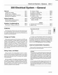
<strong>Fundamentals</strong> <strong>for</strong> <strong>the</strong> <strong>Do</strong>-<strong>it</strong>-<strong>yourself</strong> <strong>Owner</strong> <strong>100</strong>-1<br />
<strong>100</strong> <strong>Fundamentals</strong> <strong>for</strong> <strong>the</strong><br />
<strong>Do</strong>-<strong>it</strong>-<strong>yourself</strong> <strong>Owner</strong><br />
;.;.:.;.:.:.;.:.;.;.<br />
:.:.:.:...;.;.:.....<br />
General. . . . . . . . . . . . . . . . . . . . . . . . . . . . . . <strong>100</strong>-1<br />
Form and Function <strong>100</strong>-2<br />
Engine <strong>100</strong>-2<br />
<strong>Saab</strong> Turbo w<strong>it</strong>h APC <strong>100</strong>-2<br />
Fuel Injection <strong>100</strong>-3<br />
Ign<strong>it</strong>ion System. . . . . . . . . . . . . . . . . . . . . . . . <strong>100</strong>-4<br />
Electrical System . . . . . . . . . . . . . . . . . . . . . . <strong>100</strong>-4<br />
Transmission and Drive Train <strong>100</strong>-5<br />
Brakes. . . . . . . . . . . . . . . . . . . . . . . . . . . . . . . <strong>100</strong>-6<br />
Steering and Suspension . . . . . . . . . . . . . . . . <strong>100</strong>-6<br />
Body <strong>100</strong>-7<br />
I<br />
How To Use This Manual <strong>100</strong>-7<br />
Warnings, Cautions and Notes. . . . . . . . . . . . <strong>100</strong>-7<br />
,<br />
Getting Started <strong>100</strong>-8<br />
Safety . . . . . . . . . . . . . . . . . . . . . . . . . . . . . . . <strong>100</strong>-8<br />
Lifting <strong>the</strong> Car. . . . . . . . . . . . . . . . . . . . . . . . . <strong>100</strong>-8<br />
To raise car safely <strong>100</strong>-9<br />
To work safely under a car <strong>100</strong>-9<br />
General Advice <strong>for</strong> <strong>the</strong> Beginner .... <strong>100</strong>-10<br />
Planning Ahead .. . . . . . . . . . . . . . . . . . . . . <strong>100</strong>-10<br />
Cleanliness <strong>100</strong>-10<br />
Non-reusable Fasteners. . . . . . . . . . . . . . . . <strong>100</strong>-10<br />
Tightening Fasteners . . . . . . . . . . . . . . . . . . <strong>100</strong>-10<br />
Bolt Torque <strong>100</strong>-10<br />
Gaskets. . . . . . . . . . . . . . . . . . . . . . . . . . . . . <strong>100</strong>-11<br />
Seals <strong>100</strong>-11<br />
Cleaning . . . . . . . . . . . . . . . . . . . . . . . . . . . . <strong>100</strong>-11<br />
Electrical Testing ... . . . . . . . . . . . . . . . . . . <strong>100</strong>-11<br />
Wire Repairs. . . . . . . . . . . . . . . . . . . . . . . . . <strong>100</strong>-12<br />
Buying Parts <strong>100</strong>-12<br />
In<strong>for</strong>mation You Need To Know <strong>100</strong>-12<br />
Genuine <strong>Saab</strong> Parts <strong>100</strong>-12<br />
Non-returnable Parts <strong>100</strong>-14<br />
Tools <strong>100</strong>-14<br />
Basic Tool Requirements <strong>100</strong>-14<br />
Jack Stands <strong>100</strong>-16<br />
Oil Change Equipment <strong>100</strong>-16<br />
Torque Wrench <strong>100</strong>-17<br />
Feeler Gauges <strong>100</strong>-17<br />
Volt-Ohm Meter (VOM) or Multimeter <strong>100</strong>-17<br />
<strong>Saab</strong> Special Tools <strong>100</strong>-17<br />
Emergencies <strong>100</strong>-18<br />
Changing a Tire <strong>100</strong>-18<br />
Car Will Not Start <strong>100</strong>-18<br />
Jump-Starting <strong>100</strong>-18<br />
Overheating <strong>100</strong>-19<br />
Oil Pressure Warning Light <strong>100</strong>-20<br />
Brake Fluid Level Warning Light <strong>100</strong>-20<br />
Anti-Lock Brake System Warning Indicator .. <strong>100</strong>-20<br />
Dim Lights <strong>100</strong>-20<br />
Towing <strong>100</strong>-20<br />
Spare Parts K<strong>it</strong> <strong>100</strong>-20<br />
Spare Parts K<strong>it</strong> - Basic Contents <strong>100</strong>-20<br />
Spare Parts K<strong>it</strong> - Add<strong>it</strong>ional Contents <strong>100</strong>-20<br />
TABLES<br />
a. General Tightening Torques<br />
(unless noted o<strong>the</strong>rwise in text) <strong>100</strong>-11<br />
b. Bolt Diameter and Wrench Size <strong>100</strong>-11<br />
GENERAL<br />
Although <strong>the</strong> <strong>Saab</strong> <strong>900</strong> is a sophisticated and complex machine,<br />
nearly all basic maintenance and most repairs can be<br />
accomplished by any interested owner w<strong>it</strong>h basic mechanical<br />
skills and <strong>the</strong> right in<strong>for</strong>mation. While some of <strong>the</strong> repairs covered<br />
in this manual are complicated and require special<br />
knowledge and equipment, most of <strong>the</strong> care that is required in<br />
<strong>the</strong> I~etime of <strong>the</strong> average <strong>Saab</strong> is well w<strong>it</strong>hin <strong>the</strong> capabil<strong>it</strong>ies<br />
of <strong>the</strong> do-rt-<strong>yourself</strong>er.<br />
CAUTION<br />
<strong>Do</strong> not use this manual unless you are familiar w<strong>it</strong>h basic automotive<br />
repair procedures and safe workshop practices. This<br />
manual illustrates <strong>the</strong> workshop procedures required <strong>for</strong> most<br />
service work; <strong>it</strong> is not a subst<strong>it</strong>ute <strong>for</strong> full and up-to-date in<strong>for</strong>mation<br />
from <strong>the</strong> vehicle manufacturer or <strong>for</strong> proper training as<br />
an automotive technician. Note that <strong>it</strong> is not possible <strong>for</strong> us to<br />
anticipate all of <strong>the</strong> ways or cond<strong>it</strong>ions under which vehicles<br />
may be serviced or to provide cautions as to all of <strong>the</strong> possible<br />
hazards that may result.<br />
GENERAL
<strong>100</strong>-2 <strong>Fundamentals</strong> <strong>for</strong> <strong>the</strong> <strong>Do</strong>-<strong>it</strong>-<strong>yourself</strong> <strong>Owner</strong><br />
CAUTION<br />
Your common sense and good judgment are crucial to safe<br />
and successful service work. Read procedures through be<strong>for</strong>e<br />
starting <strong>the</strong>m. Think about whe<strong>the</strong>r <strong>the</strong> cond<strong>it</strong>ion of your<br />
car, your level of mechanical skill, or your level of reading<br />
comprehension might result in or contribute in some way to an<br />
occurrence which might cause you injury, damage your car, or<br />
result in an unsafe repair. If you have doubts <strong>for</strong> <strong>the</strong>se or o<strong>the</strong>r<br />
reasons about your abil<strong>it</strong>y to per<strong>for</strong>m safe repair work on your<br />
car, have <strong>the</strong> work done at an authorized <strong>Saab</strong> dealer or o<strong>the</strong>r<br />
qualified shop.<br />
This section of <strong>the</strong> manual is intended to help <strong>the</strong> beginner<br />
get started smartly and safely w<strong>it</strong>h <strong>Saab</strong> maintenance and repair.<br />
The section begins w<strong>it</strong>h Form and Function, a general<br />
description of <strong>the</strong> car and <strong>it</strong>s individual systems, followed by a<br />
discussion on How To Use This Manual.<br />
Tips on mechanic's skills and workshop practices that can<br />
help <strong>the</strong> beginner do a faster, complete, and more thorough job<br />
can be found under Getting Started. Tools describes <strong>the</strong> basic<br />
tools needed to do most of <strong>the</strong> procedures in this manual.<br />
The section ends w<strong>it</strong>h a quick reference guide to emergencies-what<br />
to do when <strong>the</strong> car won't start or when a warning<br />
light comes on, including basic troubleshooting and in<strong>for</strong>mation<br />
on how to gauge <strong>the</strong> seriousness of a problem.<br />
FORM AND FUNCTION<br />
89048<br />
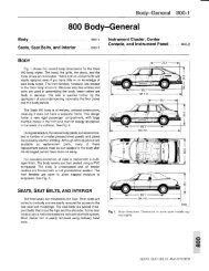
Fig. 1. Cutaway of <strong>Saab</strong> <strong>900</strong> 16 valve overhead camshaft engine.<br />
The engine is sloped at 45% to lower <strong>the</strong> car's center of grav<strong>it</strong>y<br />
and to allow <strong>for</strong> a low hood line. The transmission is bolted<br />
to <strong>the</strong> bottom of <strong>the</strong> engine.<br />
While <strong>the</strong> complex<strong>it</strong>y of <strong>the</strong> <strong>Saab</strong> <strong>900</strong> may at first seem<br />
overwhelming to <strong>the</strong> do-<strong>it</strong>-<strong>yourself</strong> owner, <strong>it</strong> can be simplified<br />
and more easily understood by viewing <strong>the</strong> car as an assembly<br />
of simpler systems, each per<strong>for</strong>ming <strong>it</strong>s own independent<br />
functions.<br />
Engine<br />
The <strong>Saab</strong> <strong>900</strong> models covered by this manual are powered<br />
by a liquid-cooled, four-cylinder, 16-valve, in-line engine. The<br />
power train is integrated w<strong>it</strong>h <strong>the</strong> clutch, transmission, and differential<br />
in a compact, lightweight power un<strong>it</strong> that occupies<br />
very l<strong>it</strong>tle space. See Fig. 1.<br />
The 16 valve cylinder head uses self-adjusting hydraulic<br />
cam followers to actuate <strong>the</strong> valves. Each valve has a large<br />
flow area to allow <strong>the</strong> engine to breath efficiently. Because <strong>the</strong><br />
cylinder head has four valves per cylinder instead of two, individual<br />
valves are subject to far less demanding working cond<strong>it</strong>ions.<br />
See Fig. 2.<br />
<strong>Saab</strong> Turbo w<strong>it</strong>h APC<br />
In add<strong>it</strong>ion to <strong>the</strong> naturally aspirated engine family, <strong>the</strong> <strong>900</strong><br />
is available w<strong>it</strong>h a turbocharged engine. See Fig. 3. The turbo<br />
Fig. 2. Cutaway view of valve train.<br />
FORM AND FUNCTION
<strong>Fundamentals</strong> <strong>for</strong> <strong>the</strong> <strong>Do</strong>-<strong>it</strong>-<strong>yourself</strong> <strong>Owner</strong> <strong>100</strong>-3<br />
engine delivers extra power at low engine speeds when demanded,<br />
but during normal driving <strong>it</strong> is as economical as <strong>the</strong><br />
naturally aspirated engine. The turbocharged engine offers<br />
<strong>the</strong> same acceleration as many six-cylinder and eight-cylinder<br />
engines, but w<strong>it</strong>hout <strong>the</strong> well-known disadvantages of excessive<br />
weight, unwieldy bulk w<strong>it</strong>h too many moving parts, and<br />
high fuel consumption.<br />
Octane rating<br />
<strong>100</strong><br />
97<br />
Energy utilization<br />
w<strong>it</strong>h APC<br />
93<br />
Risk<br />
margins<br />
91<br />
Hot eXhauslgasses<br />
~_I".""~:~<br />
89050<br />
Fig. 3. Cutaway of turbocharger system. The intake air is compressed<br />
by <strong>the</strong> exhaust-driven turbocharger, It is <strong>the</strong>n cooled<br />
by as much as 11 QOF in <strong>the</strong> intercooler be<strong>for</strong>e <strong>it</strong> enters <strong>the</strong> engine,<br />
The intercooler increases power and reduces <strong>the</strong> <strong>the</strong>rmal<br />
stresses in <strong>the</strong> engine,<br />
Safety margins must be built into <strong>the</strong> design of an internal<br />
combustion engine to allow <strong>for</strong> manufacturing tolerances,<br />
changes in <strong>the</strong> cond<strong>it</strong>ion of <strong>the</strong> engine, and varying climatic<br />
cond<strong>it</strong>ions and fuel qual<strong>it</strong>y. As a result, <strong>the</strong> energy content of<br />
<strong>the</strong> fuel cannot be fully utilized. To answer this problem, <strong>the</strong><br />
<strong>Saab</strong> APC system was .designed to ensure maximum utilization<br />
of <strong>the</strong> energy in <strong>the</strong> fuel at all times. The boost pressure<br />
delivered by <strong>the</strong> turbocharger is continually adjusted to su<strong>it</strong><br />
<strong>the</strong> knocking lim<strong>it</strong> of <strong>the</strong> air/fuel mixture in <strong>the</strong> cylinders. There<strong>for</strong>e,<br />
<strong>the</strong> engine adjusts <strong>it</strong>self automatically to <strong>the</strong> fuel being<br />
used. The higher <strong>the</strong> octane, <strong>the</strong> higher <strong>the</strong> maximum engine<br />
power. See Fig. 4.<br />
NOTE<br />
On <strong>Saab</strong> Turbo SPG models, premium unleaded fuel is required<br />
at all times.<br />
2000 4000<br />
Energy utilization<br />
w<strong>it</strong>hout APC<br />
Engine<br />
speed<br />
89051<br />
Fig. 4. A conventional engine must incorporate safety margins <strong>for</strong><br />
engine tolerances, various climatic cond<strong>it</strong>ions, and variations<br />
in fuel grades available. The <strong>Saab</strong> APC turbo engine adjusts<br />
<strong>it</strong>self automatically to su<strong>it</strong> <strong>the</strong> operating cond<strong>it</strong>ions.<br />
Fuel Injection<br />
All <strong>Saab</strong> <strong>900</strong> 16-valve models use an electronically controlled<br />
Bosch LH-Jetronic fuel injection system. See Fig. 5. LH<br />
is a German acronym <strong>for</strong> hot wire, or "Luft masse messen m<strong>it</strong><br />
h<strong>it</strong>zdraht". Hot wire refers to <strong>the</strong> operation of <strong>the</strong> air mass<br />
meter, which is used to measure <strong>the</strong> air entering <strong>the</strong> engine.<br />
The intake air flows acro~s an electrically heated platinum<br />
wire in <strong>the</strong> tubular air meter. See Fig. 6. The control un<strong>it</strong> <strong>the</strong>n<br />
measures <strong>the</strong> electrical energy necessary to maintain <strong>the</strong> wire<br />
at a constant temperature as a measure of <strong>the</strong> air mass. At <strong>the</strong><br />
same time <strong>the</strong> control un<strong>it</strong> senses <strong>the</strong> engine speed and <strong>the</strong><br />
engine temperature, which enables <strong>it</strong> to meter <strong>the</strong> correct<br />
quant<strong>it</strong>y of fuel to su<strong>it</strong> <strong>the</strong> requirements of <strong>the</strong> engine at all<br />
times.<br />
The APC system consists of simple electronics. A knock<br />
sensor on <strong>the</strong> engine block senses <strong>the</strong> onset and degree of<br />
engine knock and transm<strong>it</strong>s an electrical signal to <strong>the</strong> control<br />
un<strong>it</strong>. The control un<strong>it</strong> also receives signals from <strong>the</strong> intake<br />
manifold pressure sensor and <strong>the</strong> ign<strong>it</strong>ion system (engine<br />
rpm). The data is processed by <strong>the</strong> control un<strong>it</strong>, which transm<strong>it</strong>s<br />
a signal to <strong>the</strong> APC solenoid valve to regulate <strong>the</strong> boost<br />
pressure (via <strong>the</strong> wastegate) of <strong>the</strong> turbocharger. There<strong>for</strong>e,<br />
maximum operating boost pressure under full engine load is<br />
electronically governed. In <strong>the</strong> event of an APC system malfunction,<br />
<strong>the</strong> wastegate is mechanically adjusted to provide a<br />
safe, low boost pressure lim<strong>it</strong>.<br />
Fuel is delivered to <strong>the</strong> engine through <strong>the</strong> fuel injectors.<br />
The intake manifold is equipped w<strong>it</strong>h one fuel injector per cylinder.<br />
Each injector is f<strong>it</strong>ted upstream of <strong>the</strong> corresponding intake<br />
valves and actuated electro-magnetically by signals from<br />
<strong>the</strong> electronic control un<strong>it</strong>. The control un<strong>it</strong> calculates <strong>the</strong><br />
opening time <strong>for</strong> <strong>the</strong> injectors so that <strong>the</strong> quant<strong>it</strong>y of <strong>the</strong> fuel injected<br />
will be correct in relation to <strong>the</strong> quant<strong>it</strong>y of air flowing to<br />
<strong>the</strong> engine. See Fig. 7.<br />
FORM AND FUNCTION
<strong>100</strong>-4 <strong>Fundamentals</strong> <strong>for</strong> <strong>the</strong> <strong>Do</strong>-<strong>it</strong>-<strong>yourself</strong> <strong>Owner</strong><br />
89052<br />
1. Fuel tank w<strong>it</strong>h in-tank fuel 4. Throttle valve<br />
pump 5. Automatic Idle Control (AI C)<br />
2. Electronic control un<strong>it</strong> 6. Fuel injector<br />
3. Air mass meter 7. Temperature sensor<br />
Fig. 5. SChematic of LH-Jetronic fuel injection system used on all<br />
saab 16 valve engines.<br />
Fig. 7. Cutaway view of engine showing operation of <strong>the</strong> electromagnetic<br />
fuel injector. The injectors are mounted in <strong>the</strong> intake<br />
manifold, one <strong>for</strong> each cylinder.<br />
right time. Since each cylinder has to have a spark once <strong>for</strong><br />
every two revolutions of <strong>the</strong> crankshaft, <strong>the</strong> distributor turns at<br />
one-half crankshaft speed. The basic system is shown schematically<br />
in Fig. 8.<br />
Electrical System<br />
Many components, and all electrical accessories, are powered<br />
by <strong>the</strong> car's electrical system. The electrical system uses<br />
a battery to store energy, an engine-driven alternator to generate<br />
electric<strong>it</strong>y and recharge <strong>the</strong> battery, and various wiring<br />
harnesses and o<strong>the</strong>r circu<strong>it</strong>s to distribute electric power to <strong>the</strong><br />
rest of <strong>the</strong> car. The electrical system is represented in Fig. 9.<br />
Fig. 6. View of LH (hot wire) air mass meter. The platinum heated<br />
wire is maintained at a constant temperature and measures<br />
<strong>the</strong> mass of <strong>the</strong> air flow going into <strong>the</strong> engine. It uses solidstate<br />
circu<strong>it</strong>ry and has no moving parts to wear out. The inset<br />
shows a front view of air mass meter.<br />
Ign<strong>it</strong>ion System<br />
The electronic ign<strong>it</strong>ion system creates <strong>the</strong> high-voltage<br />
spark necessary to ign<strong>it</strong>e <strong>the</strong> combustible air/fuel mixture in<br />
<strong>the</strong> cylinders. The ign<strong>it</strong>ion coil boosts <strong>the</strong> voltage so that <strong>the</strong><br />
spark will be hot enough to ign<strong>it</strong>e <strong>the</strong> air/fuel mixture. The timing<br />
of <strong>the</strong> spark is controlled by <strong>the</strong> ign<strong>it</strong>ion control un<strong>it</strong>.<br />
The ign<strong>it</strong>ion distributor, synchronized to <strong>the</strong> rotation of <strong>the</strong><br />
engine, delivers <strong>the</strong> spark to <strong>the</strong> right cylinder at precisely <strong>the</strong><br />
The flow of electric<strong>it</strong>y depends upon a closed-loop path-a<br />
complete circu<strong>it</strong>. Electrical current flows through wires to <strong>the</strong><br />
consumer, a light bulb <strong>for</strong> example, and back to <strong>the</strong> battery in<br />
a complete circu<strong>it</strong>. The electrical route back to <strong>the</strong> source,<br />
which completes <strong>the</strong> circu<strong>it</strong>, is called a path to ground. Every<br />
consumer of electrical power in <strong>the</strong> car must have a source of<br />
power and a path to ground in order to operate.<br />
Commonly, <strong>the</strong> electrically conductive metal structure of<br />
<strong>the</strong> automobile is used as a ground path. The negative (-) terminal<br />
of <strong>the</strong> battery connects to <strong>the</strong> car body, and all of <strong>the</strong><br />
electrical consumers in <strong>the</strong> car make a ground connection to<br />
<strong>the</strong> car body, thus eliminating <strong>the</strong> need <strong>for</strong> many feet of add<strong>it</strong>ional<br />
wire.<br />
Electrical components near <strong>the</strong> engine are often grounded<br />
directly to <strong>the</strong> engine, which is <strong>the</strong>n grounded to <strong>the</strong> body.<br />
Some components are grounded through <strong>the</strong>ir housings<br />
which are bolted to a ground. Electrically, <strong>the</strong> effect is <strong>the</strong><br />
same.<br />
FORM AND FUNCTION
<strong>Fundamentals</strong> <strong>for</strong> <strong>the</strong> <strong>Do</strong>-<strong>it</strong>-<strong>yourself</strong> <strong>Owner</strong> <strong>100</strong>-5<br />
Ign<strong>it</strong>ion<br />
control<br />
un<strong>it</strong><br />
Ign<strong>it</strong>ion coil<br />
Rg. 8. SChematic of typical ign<strong>it</strong>ion system.<br />
Altemator<br />
!}]<br />
f<br />
.t=J<br />
<strong>100</strong>-6 <strong>Fundamentals</strong> <strong>for</strong> <strong>the</strong> <strong>Do</strong>-<strong>it</strong>-<strong>yourself</strong> <strong>Owner</strong><br />
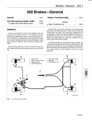
Clutch<br />
The brakes act to slow or stop <strong>the</strong> car by causing friction.<br />
Since cars are relatively heavy, <strong>the</strong> friction required to stop<br />
safely and effectively is qu<strong>it</strong>e high, and generating this friction<br />
requires considerable <strong>for</strong>ce. The cars covered by this manual<br />
use ei<strong>the</strong>r an engine vacuum boost system or hydraulic boost<br />
system (cars w<strong>it</strong>h ASS) to multiply <strong>the</strong> <strong>for</strong>ce applied to <strong>the</strong><br />
brake pedal and to distribute <strong>it</strong> uni<strong>for</strong>mly to <strong>the</strong> wheels.<br />
The brake pedal is connected by a mechanical linkage to<br />
<strong>the</strong> master cylinder, mounted on <strong>the</strong> firewall at <strong>the</strong> back of <strong>the</strong><br />
engine compartment. A piston in <strong>the</strong> master cylinder creates<br />
hydraulic pressure in <strong>the</strong> brake lines going to <strong>the</strong> wheels.<br />
Differencial w<strong>it</strong>h<br />
final drive<br />
89058<br />
Fig. 11. The gear reduction between <strong>the</strong> engine and <strong>the</strong> driven wheels<br />
takes place in three stages: <strong>the</strong> primary chain drive, <strong>the</strong> transmission<br />
gears, and <strong>the</strong> final drive,<br />
At each wheel, <strong>the</strong> hydraulic pressure acts on <strong>the</strong> brake caliper<br />
to cause friction and slow <strong>the</strong> wheel. The sizes of <strong>the</strong> hydraulic<br />
components are such that <strong>the</strong> driver's <strong>for</strong>ce applied to<br />
<strong>the</strong> brake pedal is multiplied many times by <strong>the</strong> time <strong>it</strong> reaches<br />
<strong>the</strong> wheels.<br />
1990 and later <strong>900</strong> models are equipped w<strong>it</strong>h an anti-lock<br />
braking system (ASS). As <strong>the</strong> name implies, <strong>the</strong> purpose of<br />
this system is to prevent <strong>the</strong> wheels from locking during hard<br />
braking. Speed sensors at each wheel sense when <strong>the</strong> wheel<br />
is about to lock, and an electronic system modulates <strong>the</strong> braking<br />
<strong>for</strong>ce to that wheel. See Fig. 13.<br />
Brakes<br />
All of <strong>the</strong> <strong>Saab</strong> models covered in this manual feature disc<br />
brakes at all four wheels. A disc brake squeezes pads lined<br />
w<strong>it</strong>h friction material against both sides of a flat, round brake<br />
disc, called a rotor. A typical disc brake assembly is shown in<br />
Fig. 12.<br />
Pickup<br />
coil<br />
Splash<br />
shield<br />
Too<strong>the</strong>d<br />
gearwheel<br />
89060<br />
Fig. 13. A moisture-proof sensor senses <strong>the</strong> rolling speed of each<br />
wheel. The sensor is inductive in that an electric current is induced<br />
in <strong>the</strong> pickup coil every time a tooth on <strong>the</strong> gearwheel<br />
passes <strong>the</strong> sensor,<br />
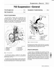
Steering and Suspension<br />
89059<br />
Fig. 12. Disc brake assembly showing disc, caliper, and splash shield,<br />
Caliper assembly holds pads w<strong>it</strong>h friction material.<br />
The suspension and steering systems are what allow <strong>the</strong><br />
wheels to move and turn <strong>for</strong> a smooth ride, stabil<strong>it</strong>y and directional<br />
control. See Fig. 14. The suspension system is <strong>the</strong> combination<br />
of springs, shock absorbers, and o<strong>the</strong>r stabilizing<br />
devices that support <strong>the</strong> weight of <strong>the</strong> car and cushion <strong>the</strong> effects<br />
of bumps. On some models, stabilizer bars aid stabil<strong>it</strong>y<br />
by transferring some of <strong>the</strong> cornering <strong>for</strong>ce acting on <strong>the</strong> suspension.<br />
FORM AND FUNCTION
<strong>Fundamentals</strong> <strong>for</strong> <strong>the</strong> <strong>Do</strong>-<strong>it</strong>-<strong>yourself</strong> <strong>Owner</strong> <strong>100</strong>-7<br />
~----------------<br />
89061<br />
Fig. 14. The suspension and steering system gives <strong>the</strong> driver control<br />
over <strong>the</strong> car by supplying constant feedback on <strong>the</strong> car's reactions.<br />
The steering system consists of <strong>the</strong> steering rack mechanisms,<br />
linkages, and a belt-driven hydraulic pump. Power-assisted<br />
steering uses hydraulic fluid under pressure to do some<br />
of <strong>the</strong> work normally done by <strong>the</strong> driver turning <strong>the</strong> steering<br />
wheel.<br />
Body<br />
The body is <strong>the</strong> basic building block. All of <strong>the</strong> <strong>Saab</strong> models<br />
covered in this manual feature un<strong>it</strong>ized body construction,<br />
meaning that <strong>the</strong>y do not have a separate frame. A complex<br />
body shell is <strong>the</strong> main structural plat<strong>for</strong>m to which all <strong>the</strong> o<strong>the</strong>r<br />
systems are attached. Subassemblies attach engine, drivetrain,<br />
suspension, and steering systems to <strong>the</strong> basic body<br />
structure.<br />
The doors, <strong>the</strong> instrument panel, <strong>the</strong> seats, and o<strong>the</strong>r interior<br />
trim pieces are also added to <strong>the</strong> body shell. O<strong>the</strong>r parts of<br />
<strong>the</strong> body shell function as mounting points <strong>for</strong> <strong>the</strong> o<strong>the</strong>r major<br />
and minor subsystems.<br />
How TO USE THIS MANUAL<br />
The manual is divided into 9 sections:<br />
oTECHNICAL DATA<br />
1 LUBRICATION AND MAINTENANCE<br />
2 ENGINE<br />
3 ELECTRICAL SYSTEM<br />
4 TRANSMISSION<br />
5 BRAKES<br />
6 STEERING AND WHEEL ALIGNMENT<br />
7 SUSPENSION<br />
8 BODY AND STEERING<br />
o TECHNICAL DATA lists all of <strong>the</strong> specifications used<br />
throughout <strong>the</strong> manual and is intended to be used as a quick<br />
reference guide <strong>for</strong> <strong>the</strong> more experienced technician familiar<br />
w<strong>it</strong>h <strong>Saab</strong> <strong>900</strong> cars. 1 LUBRICATION AND MAINTENANCE<br />
covers <strong>the</strong> maintenance schedules and service procedures<br />
needed to do all of <strong>the</strong> <strong>Saab</strong> recommended scheduled maintenance<br />
work.<br />
The remaining seven sections (2 through 8) are repair oriented<br />
and are divided into multiple repair groups. For clar<strong>it</strong>y<br />
and ease of use, each major section begins w<strong>it</strong>h a General repair<br />
group, e.g. 200 Engine-General. These "00" (double<br />
zero) groups are mostly descriptive in nature, covering topics<br />
such as <strong>the</strong>ory of operation and troubleshooting. The remainder<br />
of <strong>the</strong> repair groups contain <strong>the</strong> more involved and more<br />
detailed system repair in<strong>for</strong>mation.<br />
A master listing of <strong>the</strong> 9 sections and <strong>the</strong> corresponding 69<br />
individual repair groups can be found at <strong>the</strong> beginning of each<br />
section. Thumb tabs on <strong>the</strong> first page of each repair group<br />
page help locate <strong>the</strong> groups quickly.<br />
Each repair group has <strong>it</strong>s own Table of Contents listing <strong>the</strong><br />
major subject headings w<strong>it</strong>hin <strong>the</strong> group, and <strong>the</strong> pages on<br />
which <strong>the</strong>y begin. Page numbers throughout <strong>the</strong> manual are<br />
organized according to <strong>the</strong> repair group system. For example,<br />
you can expect to find in<strong>for</strong>mation on <strong>the</strong> turbocharger (Repair<br />
Group 291) beginning on page 291-1. A comprehensive index<br />
is found at <strong>the</strong> back of <strong>the</strong> manual.<br />
Warnings, Cautions and Notes<br />
Throughout this manual are many passages w<strong>it</strong>h <strong>the</strong> headings<br />
WARNING, CAUTION, or NOTE. These very important<br />
headings have different meanings.<br />
HOW TO USE THIS MANUAL
<strong>100</strong>-8 <strong>Fundamentals</strong> <strong>for</strong> <strong>the</strong> <strong>Do</strong>-It-<strong>yourself</strong> <strong>Owner</strong><br />
WARNING<br />
A waming is <strong>the</strong> most serious of <strong>the</strong> three. It wams of unsafe<br />
practices that are very likely to cause injury, ei<strong>the</strong>r by direct<br />
threat to <strong>the</strong> person(s) doing <strong>the</strong> work or by increased risk of<br />
accident or mechanical failure while driving.<br />
CAUTION<br />
A caution calls attention to important precautions to be observed<br />
during <strong>the</strong> repair work that will help prevent accidentally<br />
damaging <strong>the</strong> car or <strong>it</strong>s parts.<br />
NOTE<br />
A note contains helpful in<strong>for</strong>mation, tips that will help in doing<br />
a better job and completing <strong>it</strong> more easily.<br />
Please read every WARNING, CAUTION, and NOTE at <strong>the</strong><br />
front of <strong>the</strong> manual and as <strong>the</strong>y appear in repair procedures.<br />
They are very important. Read <strong>the</strong>m be<strong>for</strong>e you begin any<br />
maintenance or repair job.<br />
Some WARNINGs and CAUTIONs are repeated wherever<br />
<strong>the</strong>y apply. Read <strong>the</strong>m all. <strong>Do</strong> not skip any. These messages<br />
are important, even to <strong>the</strong> owner who never intends to work on<br />
<strong>the</strong> car.<br />
GETTING STARTED<br />
Most of <strong>the</strong> necessary maintenance and minor repair that a<br />
<strong>Saab</strong> will need can be done w<strong>it</strong>h ordinary tools, even by owners<br />
w<strong>it</strong>h l<strong>it</strong>tle or no experience in car repair. Below is some important<br />
in<strong>for</strong>mation on how to work safely, a discussion of<br />
what tools will be needed and howto use <strong>the</strong>m, and a series of<br />
mechanic's tips on methods and workmanship.<br />
Safety<br />
Although an automobile presents many hazards, common<br />
sense and good equipment can ensure safety. Accidents happen<br />
because of carelessness. Pay attention and stick to <strong>the</strong>se<br />
few important safety rules.<br />
WARNING<br />
• Remove rings, watches, and bracelets. Aside from <strong>the</strong> dangers<br />
of moving parts, metallic jewelry conducts electric<strong>it</strong>y and<br />
may cause shorts, sparks, bums, or damage to <strong>the</strong> electrical<br />
system when accidentally contacting <strong>the</strong> battery or o<strong>the</strong>r electrical<br />
terminals.<br />
• Disconnect <strong>the</strong> battery negative (-) cable whenever working<br />
on or near <strong>the</strong> fuel system or anything that is electrically powered.<br />
Accidental electrical contact may damage <strong>the</strong> electrical<br />
system or cause fire.<br />
• Never work under a lifted car unless <strong>it</strong> is solidly supported<br />
on jack stands that are intended <strong>for</strong> that purpose. <strong>Do</strong> not support<br />
a car on cinder blocks, bricks, or o<strong>the</strong>r objects that may<br />
shift or crumble under continuous load. Never work under a<br />
car that is supported only by <strong>the</strong> lifting jack.<br />
• The fuel system is designed to retain pressure even when<br />
<strong>the</strong> ign<strong>it</strong>ion is off. When working w<strong>it</strong>h <strong>the</strong> fuel system, loosen<br />
<strong>the</strong> fuel lines very slowly to allow <strong>the</strong> residual pressure to dissipate<br />
gradually. Avoid spraying fuel.<br />
• Fuel is highiy flammable. When working around fuel, do not<br />
smoke or work near heaters or o<strong>the</strong>r fire hazards. Keep an approved<br />
fire extinguisher handy.<br />
• Illuminate <strong>the</strong> work area adequately and safely. Use a portable<br />
safety light <strong>for</strong> working inside or under <strong>the</strong> car. A fluorescent<br />
type light is best because <strong>it</strong> gives off less heat. If using a<br />
light w<strong>it</strong>h a normal incandescent bulb, use rough service bulbs<br />
to avoid breakage. The hot filament of an accidentally broken<br />
bulb can ign<strong>it</strong>e spilled fuel or oil.<br />
• Keep sparks, lighted matches, and open flame away from<br />
<strong>the</strong> top of <strong>the</strong> battery. Hydrogen gas em<strong>it</strong>ted by <strong>the</strong> battery is<br />
highly flammable. Any nearby source of ign<strong>it</strong>ion may cause<br />
<strong>the</strong> battery to explode.<br />
• Never lay tools or parts in <strong>the</strong> engine compartment or on top<br />
of <strong>the</strong> battery. They may fall into confined spaces and be difficult<br />
to retrieve, become caught in belts or o<strong>the</strong>r rotating parts<br />
when <strong>the</strong> engine is started, or cause electrical shorts and<br />
damage to <strong>the</strong> electrical system.<br />
• Some of <strong>the</strong> cars covered by this manual are equipped w<strong>it</strong>h<br />
a Supplemental Restraint System (SRS) that automatically<br />
deploys an airbag. The airbag un<strong>it</strong> uses an explosive device<br />
to electrically ign<strong>it</strong>e a powerful gas. On cars so equipped, any<br />
work involving <strong>the</strong> steering wheel should only be per<strong>for</strong>med by<br />
an authorized <strong>Saab</strong> dealer. Per<strong>for</strong>ming repairs w<strong>it</strong>hout disarming<br />
<strong>the</strong> SRS may cause serious personal injury.<br />
WARNING<br />
• Never run <strong>the</strong> engine in <strong>the</strong> work area unless <strong>it</strong> is well-ventilated.<br />
The exhaust should be vented to <strong>the</strong> outside. Carbon<br />
Monoxide (CO) in <strong>the</strong> exhaust kills.<br />
• Remove all neckties, scarfs, loose clothing, or jewelry when<br />
working near running engines or power tools. Tuck in shirts.<br />
Tie long hair and secure <strong>it</strong> under a cap. Severe injury can result<br />
from <strong>the</strong>se things being caught in rotating parts.<br />
Lifting <strong>the</strong> Car<br />
For those repairs that require raising <strong>the</strong> car, <strong>the</strong> proper<br />
jacking points should be used to raise <strong>the</strong> car safely and avoid<br />
damage. There are six jacking points from which <strong>the</strong> car can<br />
be safely raised. The jack supplied w<strong>it</strong>h <strong>the</strong> car by <strong>Saab</strong> can<br />
only be used at <strong>the</strong> four side points-just behind <strong>the</strong> front<br />
wheel or just in front of <strong>the</strong> rear wheel. In add<strong>it</strong>ion to <strong>the</strong> four<br />
side points, <strong>the</strong>re are front and rear center jacking points that<br />
can be used to lift one end. See Fig. 15.<br />
GETTING STARTED
<strong>Fundamentals</strong> <strong>for</strong> <strong>the</strong> <strong>Do</strong>-<strong>it</strong>-<strong>yourself</strong> <strong>Owner</strong> <strong>100</strong>-9<br />
Lift points <strong>for</strong> car lift, jack stands, or <strong>Saab</strong>-supplied jack<br />
Floor jack lift points<br />
(floorpan rein<strong>for</strong>cement crossmembers)<br />
89062<br />
Fig. 15. saab jacking points.<br />
CAUTION<br />
When raising <strong>the</strong> car using a floor jack or a hydraulic lift, carefully<br />
pos<strong>it</strong>ion <strong>the</strong> jack pad so that <strong>it</strong> does not damage <strong>the</strong> body.<br />
A su<strong>it</strong>able liner (wood, rubber. etc.) should be placed between<br />
<strong>the</strong> jack and <strong>the</strong> car so that <strong>the</strong> underbody will not be damaged.<br />
To raise car safely<br />
1. Park <strong>the</strong> car on a flat, level surface.<br />
2. Place <strong>the</strong> jack in pos<strong>it</strong>ion. See Fig. 16. Make sure <strong>the</strong><br />
jack is resting on flat, solid ground. Use a board or o<strong>the</strong>r<br />
support to provide a firm surface <strong>for</strong> <strong>the</strong> jack, if necessary.<br />
3. Raise <strong>the</strong> car slowly.<br />
WARNING<br />
Watch <strong>the</strong> jack closely. Make <strong>it</strong> stays stable and does not shift<br />
or tilt. As <strong>the</strong> car is raised, <strong>the</strong> car will want to roll slightly and<br />
<strong>the</strong> jack will want to shift.<br />
4. Once <strong>the</strong> car is raised, block <strong>the</strong> wheel that is oppos<strong>it</strong>e<br />
and far<strong>the</strong>st from <strong>the</strong> jack to prevent <strong>the</strong> car from unexpectedly<br />
rolling.<br />
WARNING<br />
<strong>Do</strong> not rely on <strong>the</strong> transmission or <strong>the</strong> emergency brake to<br />
keep <strong>the</strong> car from rolling. While <strong>the</strong>y will help, <strong>the</strong>y are not a<br />
subst<strong>it</strong>ute <strong>for</strong> pos<strong>it</strong>ively blocking <strong>the</strong> oppos<strong>it</strong>e wheel.<br />
Never work under a car that is supported only by a jack. Use<br />
jack stands that are properly designed to support <strong>the</strong> car. See<br />
Tools.<br />
To work safely under a car<br />
1. Disconnect <strong>the</strong> battery negative (-) cable so that no<br />
one else can start <strong>the</strong> car. Let o<strong>the</strong>rs know what you will<br />
be doing.<br />
2. Raise <strong>the</strong> car slowly as described above.<br />
Fig. 16. saab-supplied jack correctly installed at front left jacking<br />
point.<br />
GETTING STARTED
<strong>100</strong>-10 <strong>Fundamentals</strong> <strong>for</strong> <strong>the</strong> <strong>Do</strong>-<strong>it</strong>-<strong>yourself</strong> <strong>Owner</strong><br />
3. Use at least two jack stands to support <strong>the</strong> car. A jack<br />
is a temporary lifting device and should not be used<br />
alone to support <strong>the</strong> car while you are under <strong>it</strong>. Use<br />
pos<strong>it</strong>ively locking jack stands that are designed <strong>for</strong> <strong>the</strong><br />
purpose of supporting a car. For more in<strong>for</strong>mation on<br />
jack stands, see Tools below.<br />
WARNING<br />
<strong>Do</strong> not use wood, concrete blocks, or bricks to support a car.<br />
Wood may spl<strong>it</strong>. Blocks or bricks, while strong, are not designed<br />
<strong>for</strong> that kind of load, and may break or collapse.<br />
4. Place jack stands on a firm, solid surface, just like <strong>the</strong><br />
jack. If necessary, use a flat board or similar solid object<br />
to provide a firm footing.<br />
5. After placing <strong>the</strong> jack stands, lower <strong>the</strong> car slowly until<br />
<strong>it</strong>s weight is fully supported by <strong>the</strong> jack stands. Watch<br />
to make sure that <strong>the</strong> jack stands do not tip or lean as<br />
<strong>the</strong> car settles on <strong>the</strong>m, and that <strong>the</strong>y are placed solidly<br />
and will not move.<br />
6. Observe all jacking precautions again when raising <strong>the</strong><br />
car to remove <strong>the</strong> jack stands.<br />
GENERAL ADVICE FOR THE BEGINNER<br />
The tips in <strong>the</strong> paragraphs that follow are general advice to<br />
help any do-<strong>it</strong>-<strong>yourself</strong> <strong>Saab</strong> owner per<strong>for</strong>m repairs and maintenance<br />
tasks more easily and more professionally.<br />
Non-reusable Fasteners<br />
Many fasteners used on <strong>the</strong> cars covered by this manual<br />
must be replaced w<strong>it</strong>h new ones when <strong>the</strong>y are removed.<br />
These include but are not lim<strong>it</strong>ed to: bolts, nuts (self-locking,<br />
nylock etc.), cotter pins, studs, brake f<strong>it</strong>tings, roll pins, pins,<br />
clips and washers. Genuine <strong>Saab</strong> parts should only be used<br />
<strong>for</strong> this purpose.<br />
Some bolts, <strong>for</strong> example, are designed to stretch during assembly<br />
and are permanently altered rendering <strong>the</strong>m unusable<br />
again. Always replace fasteners where instructed to do so.<br />
See an authorized <strong>Saab</strong> dealer <strong>for</strong> applications and ordering<br />
in<strong>for</strong>mation.<br />
Tightening Fasteners<br />
When tightening <strong>the</strong> bolts or nuts that attach a component,<br />
<strong>it</strong> is always good practice to tighten <strong>the</strong> bolts gradually and<br />
evenly to avoid misalignment or over stressing anyone portion<br />
of <strong>the</strong> component. For components sealed w<strong>it</strong>h gaskets,<br />
this method helps to ensure that <strong>the</strong> gasket will seal properly<br />
and completely.<br />
Where <strong>the</strong>re are several fasteners, tighten <strong>the</strong>m in a sequence<br />
alternating between oppos<strong>it</strong>e sides of <strong>the</strong> component.<br />
Fig. 17 shows such a sequence <strong>for</strong> tightening six bolts attaching<br />
a typical component. Repeat <strong>the</strong> sequence until all <strong>the</strong><br />
bolts are evenly tightened to <strong>the</strong> proper specification.<br />
Planning Ahead<br />
Most of <strong>the</strong> repairs and maintenance tasks described in this<br />
manual can be successfully completed by anyone w<strong>it</strong>h basic<br />
tools and abil<strong>it</strong>ies. Some cannot. To prevent getting in too<br />
deep, know what <strong>the</strong> whole job requires be<strong>for</strong>e starting. Read<br />
<strong>the</strong> procedure thoroughly, from beginning to end, in order to<br />
know just what to expect and what parts will have to be replaced.<br />
Cleanliness<br />
Keeping things organized, neat, and clean is essential to<br />
doing a good job, and a more satisfying way to work. When<br />
working under <strong>the</strong> hood, fender covers will protect <strong>the</strong> 'finish<br />
from scratches and o<strong>the</strong>r damage. Make sure <strong>the</strong> car is relatively<br />
clean so that dirt under <strong>the</strong> cover does not scratch.<br />
Avoid getting tools or clothing near <strong>the</strong> battery. Battery electrolyte<br />
is a corrosive acid. Be careful w<strong>it</strong>h brake fluid, as <strong>it</strong> can<br />
cause permanent damage to <strong>the</strong> car's paint. Finally, keep rubber<br />
parts such as hoses and belts free from oil or gasoline, as<br />
<strong>the</strong>y will cause <strong>the</strong> material to soften and fail prematurely.<br />
Fig. 17. Sequence <strong>for</strong> alternately tightening multiple fasteners.<br />
For some repairs a specific tightening sequence is necessary,<br />
or a particular order of assembly is required. Such special<br />
cond<strong>it</strong>ions are noted in <strong>the</strong> text, and <strong>the</strong> necessary<br />
sequence is described or illustrated.<br />
Bolt Torque<br />
Tightening fasteners to a specified torque value using a<br />
torque wrench is a good way to ensure that bolts are correctly<br />
tightened. If a torque wrench is not used <strong>the</strong>re is a danger of<br />
going too far and damaging <strong>the</strong> fastener or <strong>the</strong> threads in <strong>the</strong><br />
mating part.<br />
GENERAL ADVICE FOR THE BEGINNER
<strong>Fundamentals</strong> <strong>for</strong> <strong>the</strong> <strong>Do</strong>-<strong>it</strong>-<strong>yourself</strong> <strong>Owner</strong> <strong>100</strong>-11<br />
Too l<strong>it</strong>tle torque on a fastener can also cause problems. Vibration<br />
of assembled parts can subject fasteners to stress alternating<br />
in oppos<strong>it</strong>e directions that will eventually cause <strong>the</strong>m<br />
to loosen. To counter this loosening, fasteners are tightened<br />
more and actually stretched a small amount.<br />
When special tightening torques are required, <strong>the</strong>y are listed<br />
in <strong>the</strong> text where <strong>the</strong> fastener is being installed. If <strong>the</strong>re is<br />
no torque listed <strong>for</strong> a specific fastener, use Table a as a general<br />
guide. The sizes listed are <strong>for</strong> <strong>the</strong> bolt thread diameter,<br />
not <strong>the</strong> size of <strong>the</strong> wrench. Table b lists <strong>the</strong> most common<br />
wrench sizes <strong>for</strong> <strong>the</strong> bolts used on <strong>the</strong> cars covered by this<br />
manual.<br />
Table a. General Tightening Torques<br />
(unless noted o<strong>the</strong>rwise in text)<br />
Bolt diameter Nm I ft~lb<br />
M5 5 -+3.5 (44 in-Ib)<br />
M6 10 7.5 (89 in-Ib)<br />
M8 20 15<br />
M10 40 30<br />
Table b. Bolt Diameter and Wrench Size<br />
Bolt diameter<br />
Most Common Wrench Size<br />
M5 8mm l<br />
M6<br />
M8 ::::or 13mm ==<br />
M10 17mm -<br />
M12<br />
M14<br />
Gaskets<br />
19mm<br />
22mm<br />
The smoo<strong>the</strong>st metal mating surfaces still have imperfections<br />
that can allow leakage. To prevent leakage at cr<strong>it</strong>ical<br />
joints, gaskets of soft, <strong>for</strong>m-f<strong>it</strong>ting material are used to fill in <strong>the</strong><br />
imperfections.<br />
To be most effective, gaskets are designed to crush and become<br />
thinner as <strong>the</strong> mating parts are bolted toge<strong>the</strong>r. Once a<br />
gasket has been used and crushed, <strong>it</strong> is no longer capable of<br />
making as good a seal as when new, and is much more likely<br />
to leak. Forthis reason, gaskets should not be reused. Always<br />
plan to use new gaskets <strong>for</strong> any reassembly. Some gasketssuch<br />
as headgaskets are directional. Make sure that <strong>the</strong>se<br />
are being installed correctly. This same logic applies to any<br />
part used <strong>for</strong> sealing, including rubber O-rings and copper<br />
sealing washers.<br />
Seals<br />
In places where a shaft must pass through a housing, flexible<br />
lip seals are used to keep <strong>the</strong> lubricating oil or grease from<br />
leaking out past <strong>the</strong> rotating shaft.<br />
Seals are designed to be installed in <strong>the</strong> housing only once<br />
and should never be reused. As long as <strong>the</strong>y are not removed<br />
from <strong>the</strong> housing and not leaking, <strong>the</strong>y need not be replaced.<br />
Seals, however, do age and deteriorate, and <strong>the</strong>re is no easier<br />
time to replace <strong>the</strong>m than when <strong>the</strong> car is already apart <strong>for</strong><br />
some o<strong>the</strong>r repair.<br />
When doing repairs that require removing a seal, be very<br />
careful not to scratch or o<strong>the</strong>rwise damage <strong>the</strong> metal surfaces.<br />
Even minor damage to sealing surfaces can cause seal<br />
damage and leakage.<br />
The key to seal installation is to get <strong>the</strong> seal in straight w<strong>it</strong>hout<br />
damaging <strong>it</strong>. Use an object that is <strong>the</strong> same diameter as<br />
<strong>the</strong> seal housing to gently and evenly drive <strong>it</strong> into place. If a<br />
proper size seal driver is not available, a socket of <strong>the</strong> right<br />
size will do.<br />
Coat <strong>the</strong> entire seal w<strong>it</strong>h oil to help <strong>it</strong> go in more easily.<br />
Seals are directional. Make sure that <strong>it</strong> is being installed w<strong>it</strong>h<br />
<strong>the</strong> lip facing <strong>the</strong> correct way. Normally <strong>the</strong> lip faces <strong>the</strong> inside.<br />
Notice <strong>the</strong> installation direction of <strong>the</strong> old seal be<strong>for</strong>e removing<br />
<strong>it</strong>.<br />
Cleaning<br />
Any repair job will be less troublesome if <strong>the</strong> parts are clean.<br />
For cleaning old parts, <strong>the</strong>re are any number of solvents and<br />
parts cleaners available commercially.<br />
For cleaning parts prior to assembly, commercially available<br />
aerosol cans of carburetor cleaner or brake cleaner are<br />
handy to use, and <strong>the</strong> cleaner will evaporate completely, leaving<br />
no residue.<br />
WARNING<br />
Virtually all solvents used <strong>for</strong> cleaning parts are highly flammable,<br />
especially in aerosol <strong>for</strong>m. Use w<strong>it</strong>h extreme care. <strong>Do</strong><br />
not smoke. <strong>Do</strong> not use <strong>the</strong>se products near any source of<br />
sparks or flame.<br />
Let any solvent or cleaning product dry completely. Lowpressure,<br />
dry compressed air is helpful if available. Also, use<br />
only Iint-Iree rags <strong>for</strong> cleaning and drying.<br />
Electrical Testing<br />
A great many electrical problems can be understood and<br />
solved w<strong>it</strong>h only a l<strong>it</strong>tle fundamental knowledge of how electrical<br />
Circu<strong>it</strong>s function.<br />
GENERAL ADVICE FOR THE BEGINNER
<strong>100</strong>-12 <strong>Fundamentals</strong> <strong>for</strong> <strong>the</strong> <strong>Do</strong>-<strong>it</strong>-<strong>yourself</strong> <strong>Owner</strong><br />
Electric current only flows in a complete circu<strong>it</strong>. To operate,<br />
every electrical device in <strong>the</strong> car requires a complete circu<strong>it</strong> including<br />
a voltage source and a path to ground. The pos<strong>it</strong>ive<br />
(+) side of <strong>the</strong> battery is <strong>the</strong> original voltage source, and<br />
ground is any return path to <strong>the</strong> negative (-) side of <strong>the</strong> battery,<br />
whe<strong>the</strong>r through <strong>the</strong> wiring harness or <strong>the</strong> car body. Except<br />
<strong>for</strong> portions of <strong>the</strong> charging system, all electrical current<br />
in <strong>the</strong> car is direct current (DC) and flows from pos<strong>it</strong>ive (+) to<br />
negative (-).<br />
Sw<strong>it</strong>ches are used·to turn components on or off by completing<br />
or interrupting <strong>the</strong> circu<strong>it</strong>. A sw<strong>it</strong>ch is "open" when <strong>the</strong> circu<strong>it</strong><br />
is interrupted, and "closed" when <strong>the</strong> circu<strong>it</strong> is completed.<br />
Fig. 18 shows a complete circu<strong>it</strong> schematically. See 3 ELEC<br />
TRICAL SYSTEM <strong>for</strong> electrical troubleshooting.<br />
Direction<br />
of current flow<br />
•<br />
Insulate <strong>the</strong> finished connection. Electronics stores can<br />
supply heat-shrinkable insulating tubing that can be placed<br />
onto <strong>the</strong> wire be<strong>for</strong>e connecting, slid over <strong>the</strong> finished joint,<br />
and shrunk to a tight f<strong>it</strong> w<strong>it</strong>h a heat gun or hair dryer. The next<br />
best alternative is electrical tape. Make sure <strong>the</strong> wire is clean<br />
and free of solder flux or o<strong>the</strong>r contamination. Wrap <strong>the</strong> joint<br />
tightly and completely to seal out moisture.<br />
BUYING PARTS<br />
Many of <strong>the</strong> maintenance and repair tasks in this manual<br />
call <strong>for</strong> <strong>the</strong> installation of new parts, or <strong>the</strong> use of new gaskets<br />
and o<strong>the</strong>r materials when reinstalling parts. Most often, <strong>the</strong><br />
parts that will be needed should be on hand be<strong>for</strong>e beginning<br />
<strong>the</strong> job. Read <strong>the</strong> introductory text and <strong>the</strong> complete proce<br />
dure to determine which parts will be needed.<br />
NOTE<br />
For some bigger jobs, partial disassembly and inspection are<br />
required to determine a complete parts list. Read <strong>the</strong> procedure<br />
carefully and, if necessary, make o<strong>the</strong>r arrangements to<br />
get <strong>the</strong> necessary parts while your car is disassembled.<br />
Car body<br />
(ground)<br />
Fig. 18. Schematic representation of simple circu<strong>it</strong> <strong>for</strong> light bulb.<br />
Sw<strong>it</strong>ch is shown closed, making circu<strong>it</strong> complete.<br />
Wire Repairs<br />
Repairs to a wiring harness to reconnect broken wires or correct<br />
shorts to ground deserve special care to make <strong>the</strong> repair<br />
permanent. The wire ends must be clean. If frayed or o<strong>the</strong>rwise<br />
damaged, cut off <strong>the</strong> end. If <strong>the</strong> wire is too short, splice in a new<br />
piece of wire of <strong>the</strong> same size and make two connections.<br />
Use connectors that are designed <strong>for</strong> <strong>the</strong> purpose.<br />
Crimped-on or soldered-on connectors are best. Crimp connectors<br />
and special crimping pliers are widely available. If soldering,<br />
use a needlenose pliers to hold <strong>the</strong> wire near <strong>the</strong><br />
solder joint and create a "heat dam". This keeps <strong>the</strong> heat and<br />
<strong>the</strong> solder from traveling up <strong>the</strong> wire. Always use a solder<br />
made specifically <strong>for</strong> electrical work.<br />
NOTE<br />
Twisting wires toge<strong>the</strong>r is really only a temporary repair, since<br />
corrosion and vibration will eventually spoil <strong>the</strong> connection.<br />
In<strong>for</strong>mation You Need To Know<br />
Fig. 19 shows <strong>the</strong> locations of <strong>the</strong> important in<strong>for</strong>mation that<br />
may be necessary to have on hand when buying parts or having<br />
work done on <strong>the</strong> car.<br />
Genuine <strong>Saab</strong> Parts<br />
Genuine <strong>Saab</strong> replacement parts from an authorized <strong>Saab</strong><br />
dealer are designed and manufactured to <strong>the</strong> same high standards<br />
as <strong>the</strong> original parts. They will be <strong>the</strong> correct material,<br />
manufactured to <strong>the</strong> same specifications, and guaranteed to<br />
f<strong>it</strong> and work as intended by <strong>the</strong> engineers who designed <strong>the</strong><br />
car. Some genuine <strong>Saab</strong> parts have a lim<strong>it</strong>ed warranty.<br />
Many independent repair shops make a point of using genuine<br />
<strong>Saab</strong> parts, even though <strong>the</strong>y may at times be more expensive.<br />
They know <strong>the</strong> value of doing <strong>the</strong> job right w<strong>it</strong>h <strong>the</strong><br />
right parts. Parts from o<strong>the</strong>r sources can be as good, particularly<br />
if manufactured by one of <strong>Saab</strong>s original equipment suppliers,<br />
but <strong>it</strong> is often difficult to know.<br />
<strong>Saab</strong> is constantly updating and improving <strong>the</strong>ir cars, often<br />
making improvements during a given model year. <strong>Saab</strong> may<br />
recommend a newer, improved part as a replacement, and<br />
your authorized dealer's parts department will know about <strong>it</strong><br />
and provide <strong>it</strong>. The <strong>Saab</strong> parts organization is best equipped<br />
to deal w<strong>it</strong>h any <strong>Saab</strong> parts needs.<br />
BUYING PARTS
I<br />
<strong>Fundamentals</strong> <strong>for</strong> <strong>the</strong> <strong>Do</strong>-<strong>it</strong>-<strong>yourself</strong> <strong>Owner</strong> <strong>100</strong>-13<br />
Transmission number,<br />
automatic transmission<br />
o ~ ~AB AUTOMOBILE ABI 0<br />
=-- ~<br />
::::':'~OOOOOGOOQQQ]<br />
:~•• L:QQo 0 kll =:::J<br />
:::~~: C=OOOO ~=:::J<br />
:::-":=;.CEQ<strong>Do</strong>o kg<br />
o ;:::o:::.cr:::-OOOO . kg -~ 0<br />
Chassis numberplate,<br />
1991 andlatermodels<br />
1t"..:",C ... J':"') J It, •• (ItHII<br />
.f}j'J"<br />
~<br />
Colour code plate, body and<br />
trim, 1986-1989 models<br />
(j :: I ::.']1:: ,': ".ob~ II<br />
~ ",:0(1.'", :""'0('7' II<br />
Colour code plate, body and<br />
trim 1989-1990 models<br />
1 • • ,n k<br />
2· 'JIO'"<br />
Chassis data plate,<br />
1985-1990 models<br />
Colour code plate, bodyand<br />
trim, 1991 models"<br />
Gearbox number<br />
manual gearbox<br />
1985 models<br />
Engine number,<br />
Two-tone colour code<br />
body<br />
~,<br />
~<br />
~<br />
'--------~~~~~~~~~<br />
Body c%ur code<br />
Chassis number stamped on<br />
rear cross-member (under floor<br />
hatch in luggage compartment)<br />
from 1981 models<br />
Production label<br />
Spare parts label<br />
Anti-<strong>the</strong>ft label from<br />
<strong>the</strong> 1987 models<br />
(cars <strong>for</strong> <strong>the</strong> U.S.A.)<br />
Trim c%ur code<br />
'.. ,, __U"\~:-~ ..~~<br />
C"lI4I ._.... ':::;::-:==..:~:~'-~<br />
CO ~':';~~:;":'~~-""':~'.-<br />
~~~~~~~~~:<br />
'" :~,-:'''',~:7:.==~~<br />
Exhaust emission control data<br />
"Colour code plate on passenger doorpillar,<br />
1992 and latermodels<br />
Fig. 19. Locations of important in<strong>for</strong>mation that may be required when<br />
buying parts,<br />
BUYING PARTS
<strong>100</strong>-14 <strong>Fundamentals</strong> <strong>for</strong> <strong>the</strong> <strong>Do</strong>-<strong>it</strong>-<strong>yourself</strong> <strong>Owner</strong><br />
Non-returnable Parts<br />
Some parts cannot be returned <strong>for</strong> cred<strong>it</strong>, even if <strong>the</strong>y are<br />
<strong>the</strong> wrong parts <strong>for</strong> <strong>the</strong> car. The best example is electrical<br />
parts, which are almost universally considered non-returnable<br />
because <strong>the</strong>y are so easily damaged internally.<br />
Buy electrical parts carefully, and be as sure as possible<br />
that a replacement is needed, especially <strong>for</strong> expensive parts<br />
such as control un<strong>it</strong>s. It may be wise to let an authorized <strong>Saab</strong><br />
dealer or o<strong>the</strong>r qualified shop confirm your diagnosis be<strong>for</strong>e<br />
replacing an expensive part that cannot be returned.<br />
TOOLS<br />
Most maintenance can be accomplished w<strong>it</strong>h a small selection<br />
of <strong>the</strong> right tools. Tools range in qual<strong>it</strong>y from inexpensive<br />
junk, which may break at first use, to very expensive and wellmade<br />
tools which, to <strong>the</strong> professional, are worth every b<strong>it</strong> of<br />
<strong>the</strong>ir high cost. The best tools <strong>for</strong> most do-<strong>it</strong>-<strong>yourself</strong> <strong>Saab</strong><br />
owners lie somewhere in between.<br />
Cheap tools are not a bargain. They often do not hold up to<br />
even casual use, and <strong>the</strong>y present a greater risk of personal<br />
injury. If <strong>the</strong>y f<strong>it</strong> poorly, <strong>the</strong>y can actually damage <strong>the</strong> fasteners<br />
<strong>the</strong>y are intended to remove, making <strong>it</strong> that much harderto<br />
use a good tool <strong>the</strong> next time around.<br />
Many reputable tool manufacturers offer good qual<strong>it</strong>y, moderately<br />
priced tools w<strong>it</strong>h a lifetime guarantee. A broken tooi<br />
can be exchanged <strong>for</strong> a new one, <strong>for</strong><strong>the</strong> life of <strong>the</strong> tool. These<br />
are your best buy. They cost a l<strong>it</strong>tle more, but <strong>the</strong>y are good<br />
qual<strong>it</strong>y tools that will do what is expected of <strong>the</strong>m. Sears'<br />
Craftsman® line is one such source of good qual<strong>it</strong>y, reasonably<br />
priced, and guaranteed tools. O<strong>the</strong>r sources of special<br />
tools are:<br />
Schley Products Inc.<br />
5350 E. Hunter Ave., Anaheim Hills, CA 92807<br />
(714) 693-7666<br />
Baum Tools Unltd. Inc.<br />
P.O. Box 87, Longboat Key, FL 34228<br />
(800) 848-6657<br />
Assenmacher Specialty Tools<br />
6440 Odell Place, Boulder, CO 80301<br />
(303) 530-2424<br />
Basic Tool Requirements<br />
NOTE<br />
<strong>Saab</strong>s are delivered w<strong>it</strong>h a tool k<strong>it</strong> mounted to <strong>the</strong> underside<br />
of <strong>the</strong> trunk lid. The k<strong>it</strong> contains a basic selection of tools that<br />
may fulfill some of <strong>the</strong> requirements listed in this section.<br />
TOOLS<br />
The basic hand tools described below can be used to accomplish<br />
most of <strong>the</strong> simple maintenance and repair tasks.<br />
Screwdrivers. Three types, <strong>the</strong> common 'flat-blade type,<br />
<strong>the</strong> Phillips type will handle almost all screws used on <strong>Saab</strong>s.<br />
Two or three different sizes of each type will be best, since a<br />
screwdriver of <strong>the</strong> wrong size will damage <strong>the</strong> screw head. On<br />
late models <strong>Saab</strong>s, Torx® screw are qu<strong>it</strong>e common. A T25<br />
size Torx driver will handle most of <strong>the</strong>se screws.<br />
A complete set of screwdrivers can often be purchased <strong>for</strong><br />
about <strong>the</strong> same money as <strong>the</strong> four or six individual ones that<br />
are really necessary. See Fig. 20.<br />
( t] < ::::-
I<br />
!<br />
<strong>Fundamentals</strong> <strong>for</strong> <strong>the</strong> <strong>Do</strong>-<strong>it</strong>-<strong>yourself</strong> <strong>Owner</strong> <strong>100</strong>-15<br />
I<br />
I<br />
I<br />
I<br />
89070<br />
I<br />
89068~<br />
------------------<br />
Fig. 21. Types of wrench heads. From left, open-end, 12-point boxend,<br />
6-polnt box-end, flare nut.<br />
Fig. 23. SocKets, extensions, and a ratchet handle,<br />
As a start, 6-point sockets w<strong>it</strong>h a 3/8 in. square drive, two or<br />
three 3/8 in. extensions of different lengths, and a 3/8 in. drive<br />
ratchet handle will be su<strong>it</strong>able <strong>for</strong> most jobs.<br />
For a more complete tool box, add deep sockets and a<br />
greater variety of handles and extensions. A universal joint<br />
extension can allow access from an angle where a straight extension<br />
will not qu<strong>it</strong>e f<strong>it</strong>.<br />
=I<br />
Spark Plug Socket. A special socket <strong>for</strong> spark plugs is <strong>the</strong><br />
correct size, is deep enough to accommodate a spark plug's<br />
length, and includes a rubber insert to both protect <strong>the</strong> spark<br />
plug from damage and grip <strong>it</strong> <strong>for</strong> easier removal. The spark<br />
plugs used in <strong>Saab</strong> engines require a 5/8 in. socket. See Fig.<br />
24.<br />
I<br />
-<br />
89069<br />
Fig. 22. Combination wrenches w<strong>it</strong>h one open-end and one 12-point<br />
box-end.<br />
Sockets. Sockets per<strong>for</strong>m <strong>the</strong> same job as box-end<br />
wrenches, but offer greater flexibil<strong>it</strong>y. They are normally used<br />
w<strong>it</strong>h a ratchet handle <strong>for</strong> speed and convenience, and can be<br />
combined w<strong>it</strong>h extensions to reach fasteners more easily.<br />
Standard sockets come in 6-point and 12-point styles. For<br />
use w<strong>it</strong>h a ratchet <strong>the</strong> 6-point offers a better grip on tight nuts<br />
and bolts. As w<strong>it</strong>h wrenches, 6mm to 15mm, 17mm, and<br />
19mm are <strong>the</strong> most needed sizes. See Fig. 23.<br />
Sockets come w<strong>it</strong>h different size connections to drive handles<br />
or extensions, called <strong>the</strong> drive size. The most common<br />
drive sizes are 1/4 in., 3/8 in., and 1/2 in.<br />
Fig. 24. Spark plug socket (5/8 in.).<br />
89071<br />
Pliers. A few of <strong>the</strong> many types of pliers are shown in Fig.<br />
25. Most are used <strong>for</strong> holding irregular objects, bending, or<br />
crimping. Some have special applications.<br />
A needlenose plier is used <strong>for</strong> gripping small and poorly accessible<br />
objects, and is useful <strong>for</strong> wiring and o<strong>the</strong>r electrical<br />
work. A locking plier such as <strong>the</strong> well-known Vise-Grip® is<br />
useful because of <strong>it</strong>s tight grip.<br />
TOOLS
<strong>100</strong>-16 <strong>Fundamentals</strong> <strong>for</strong> <strong>the</strong> <strong>Do</strong>-<strong>it</strong>-<strong>yourself</strong> <strong>Owner</strong><br />
Use only jack stands that are designed <strong>for</strong> <strong>the</strong> purpose.<br />
Blocks of wood, concrete, bricks, etc. are not safe or su<strong>it</strong>able<br />
subst<strong>it</strong>utes.<br />
Jack stands are available in several styles. A typical jack<br />
stand is shown in Fig. 27. The best ones are made of heavy<br />
material <strong>for</strong> strength, have a wide base <strong>for</strong> stabil<strong>it</strong>y, and are<br />
equipped to pos<strong>it</strong>ively lock in <strong>the</strong>ir raised pos<strong>it</strong>ions. Get <strong>the</strong><br />
best ones available.<br />
B9072<br />
Fig. 25. Pliers, From left, snap-ring, needlenose, Channel-Iock®,<br />
common, locking,<br />
Snap-ring and circlip pliers w<strong>it</strong>h special tipped jaws are<br />
used to remove and install snap-rings or circlips. A Channellock®<br />
or water pump plier has adjustable jaws that can be<br />
quickly changed to match <strong>the</strong> size of <strong>the</strong> object being held to<br />
give greater leverage.<br />
Adjustable wrench can be a useful add<strong>it</strong>ion to a small tool<br />
k<strong>it</strong>. See Fig. 26. It can subst<strong>it</strong>ute in a pinch, if two wrenches of<br />
<strong>the</strong> same size are needed to remove a nut and bolt. Use extra<br />
care w<strong>it</strong>h adjustable wrenches, as <strong>the</strong>y especially tend to<br />
loosen, slip, and damage fasteners.<br />
B9074<br />
Fig. 27. Jack stand <strong>for</strong> safely supporting car to work underneath.<br />
Oil Change Equipment<br />
Changing engine oil requires a box-end wrench or socket to<br />
loosen and tighten <strong>the</strong> drain plug 19mm (13mm on 1991 and<br />
later cars), a drain pan (at least 7 qt. capac<strong>it</strong>y), and an oil filter<br />
wrench. These <strong>it</strong>ems are shown in Fig. 28. A wide, low drain<br />
pan will f<strong>it</strong> more easily under <strong>the</strong> car. Use a funnel to pour <strong>the</strong><br />
new oil into <strong>the</strong> engine.<br />
B9073<br />
An oil filter wrench is needed <strong>for</strong> some models to remove<br />
<strong>the</strong> oil filter. Be sure to get a filter wrench that will grip <strong>the</strong> <strong>Saab</strong><br />
oil filter tightly.<br />
Fig. 26. Adjustable wrench,<br />
Compared to a wrench of <strong>the</strong> correct size, an adjustable<br />
wrench is always second best. They should only be used<br />
when <strong>the</strong> correct size wrench is not available. Choose one of<br />
average size range, about 6 to 8 inches in length.<br />
Jack Stands<br />
Strong jack stands are extremely important <strong>for</strong> any work<br />
that is done under <strong>the</strong> car. Jacks are designed only <strong>for</strong> short<br />
term use and are not solid enough to support <strong>the</strong> car <strong>for</strong> a long<br />
period. A jack should never be used alone to support <strong>the</strong> car<br />
while working underneath.<br />
B9075<br />
Fig. 28. Oil change equipment includes drain plug wrench (19mm or<br />
13mm), 7 qt. drain pan, oil filter wrench, and funnel.<br />
TOOLS
<strong>Fundamentals</strong> <strong>for</strong> <strong>the</strong> <strong>Do</strong>-<strong>it</strong>-<strong>yourself</strong> <strong>Owner</strong> <strong>100</strong>-17<br />
Torque Wrench<br />
A torque wrench is used to precisely tighten threaded fasteners<br />
to a predetermined value. Nearly all of <strong>the</strong> repair procedures<br />
in this manual include <strong>Saab</strong>-specified torque values in<br />
Newton-meters (Nm) and <strong>the</strong> equivalent values in footpounds<br />
(ft-Ib).<br />
Several types of torque wrenches are widely available.<br />
They all do <strong>the</strong> same job, but offer different convenience features<br />
at different prices. Two typical torque wrenches are<br />
shown in Fig. 29. The most convenient ones have a built-in<br />
ratchet, and can be preset to indicate when a specific torque<br />
value has been reached. Follow <strong>the</strong> wrench manufacturer's<br />
directions <strong>for</strong> use to achieve <strong>the</strong> greatest accuracy.<br />
I<br />
I L<br />
B9077<br />
Fig. 30. Feeler gauge set, used <strong>for</strong> precise measurement of clearances<br />
between parts.<br />
meters have automotive functions such as dwell and pulse<br />
width that are useful <strong>for</strong>troubleshooting ign<strong>it</strong>ion and fuel injection<br />
problems.<br />
_<br />
B9076<br />
Fig. 29. Torque wrenches, Inexpensive beam-type (top) is adequate<br />
but must be read visually, Ratchet-type (bottom) can be preset<br />
to indicate when torque value has been reached,<br />
Fig. 31. Multimeter w<strong>it</strong>h test probes.<br />
B9079<br />
A torque wrench w<strong>it</strong>h a range up to about 250 Nm (185 ft-Ib)<br />
has adequate capac<strong>it</strong>y <strong>for</strong> most of <strong>the</strong> repairs covered in this<br />
manual. For recommended torque values of 10 Nm or below,<br />
<strong>the</strong> English system equivalent is given in inch-pounds (in-Ib).<br />
These small values may be most easily reached using a<br />
torque wrench calibrated in inch-pounds. To convert footpounds<br />
to inch-pounds, multiply by 12. To convert inchpounds<br />
to foot-pounds, divide by 12.<br />
CAUTION<br />
Ign<strong>it</strong>ion, fuel injection, emission controls and o<strong>the</strong>r electronic<br />
systems may be damaged by <strong>the</strong> high current draw of a test<br />
light w<strong>it</strong>h a nonnal incandescent bulb. As a general rule, use<br />
a high impedance dig<strong>it</strong>al multimeter or an LED test light <strong>for</strong> all<br />
electrical testing.<br />
Feeler Gauges<br />
Feeler gauges are thin metal strips of precise thickness,<br />
used to measure small clearances. They are normally available<br />
as a set, covering a range of sizes. For <strong>Saab</strong>s, metric<br />
feeler gauges (in millimeters) are <strong>the</strong> best choice. Fig. 30<br />
shows a set of feeler gauges.<br />
Volt-Ohm Meter (VOM) or Multimeter<br />
Many of <strong>the</strong> electrical tests in this manual call <strong>for</strong> <strong>the</strong> measurement<br />
of resistance (ohms) or voltage values. For safe and<br />
accurate tests of ign<strong>it</strong>ion, fuel injection, and emission control<br />
systems, <strong>the</strong> multimeter, shown in Fig. 31, should be dig<strong>it</strong>al,<br />
w<strong>it</strong>h high (at least 10,000 ohms) input impedance. Some<br />
<strong>Saab</strong> Special Tools<br />
Some of <strong>the</strong> more challenging repairs covered in this manual<br />
call <strong>for</strong> <strong>the</strong> use of <strong>Saab</strong> special tools. This, however, does<br />
not automatically mean that <strong>the</strong> job is too complicated or out of<br />
reach of <strong>the</strong> novice.<br />
Many of <strong>the</strong> <strong>Saab</strong> special tools mentioned in this manual<br />
are inexpensive and are simply <strong>the</strong> best thing to use to do <strong>the</strong><br />
job correctly. In <strong>the</strong>se cases, <strong>the</strong> tool is identified w<strong>it</strong>h a <strong>Saab</strong><br />
part number. See your authorized <strong>Saab</strong> dealer parts department<br />
<strong>for</strong> in<strong>for</strong>mation on how to order special tools.<br />
There are some jobs <strong>for</strong> which expensive special tools are<br />
essential, and not a cost-effective purchase <strong>for</strong> one-time re-<br />
TOOLS
<strong>100</strong>-18 <strong>Fundamentals</strong> <strong>for</strong> <strong>the</strong> <strong>Do</strong>-<strong>it</strong>-<strong>yourself</strong> <strong>Owner</strong><br />
pair by <strong>the</strong> do-<strong>it</strong>-<strong>yourself</strong> owner. This manual includes such<br />
repairs <strong>for</strong> <strong>the</strong> benef<strong>it</strong> of those w<strong>it</strong>h <strong>the</strong> necessary experience<br />
and access to tools. For <strong>the</strong> do-<strong>it</strong>-<strong>yourself</strong>er, <strong>the</strong> need <strong>for</strong> special<br />
tools is noted in <strong>the</strong> text, and whe<strong>the</strong>r or not <strong>Saab</strong> dealer<br />
service is recommended.<br />
NOTE<br />
Be sure to read <strong>the</strong> cautions under Jump Starting prior to<br />
jump starting a low battery. Failure to follow <strong>the</strong> cautions may<br />
result in damage to <strong>the</strong> electronic components in <strong>the</strong> car.<br />
EMERGENCIES<br />
Changing a Tire<br />
If a tire goes Hat while driving, pull well off <strong>the</strong> road. Changing<br />
a tire on a busy street or highway is very dangerous. If necessary,<br />
drive a short distance on <strong>the</strong> flat tire to get to a safe<br />
place. It is much better to ruin a tire or rim than to risk being h<strong>it</strong>.<br />
Stop <strong>the</strong> car on as flat a surface as possible, in a place<br />
where you can be easily seen by o<strong>the</strong>r drivers. Avoid stopping<br />
just over <strong>the</strong> crest of a hill. Turn on <strong>the</strong> emergency flashers,<br />
and set out flares or emergency markers well behind <strong>the</strong> car.<br />
Passengers should get out of <strong>the</strong> car and stand well away<br />
from <strong>the</strong> road. Take <strong>the</strong> jack, tools, and spare wheel from <strong>the</strong><br />
trunk. Chock <strong>the</strong> wheel diagonally oppos<strong>it</strong>e to <strong>the</strong> one being<br />
changed.<br />
Loosen <strong>the</strong> wheel bolts while <strong>the</strong> car is on <strong>the</strong> ground, but<br />
leave <strong>the</strong>m a l<strong>it</strong>tle snug. Place <strong>the</strong> jack under in <strong>the</strong> lifting point<br />
nearest <strong>the</strong> wheel being changed (lifting points are shown<br />
above in Fig. 15). Use a board to provide a firm footing <strong>for</strong> <strong>the</strong><br />
jack if <strong>the</strong> ground is soft. Raise <strong>the</strong> car only far enough so that<br />
<strong>the</strong> wheel is off <strong>the</strong> ground, and <strong>the</strong>n remove <strong>the</strong> wheel bolts and<br />
<strong>the</strong> wheel. Remove <strong>the</strong> lug bolts or nuts and remove <strong>the</strong> tire.<br />
Install <strong>the</strong> spare wheel. Install <strong>the</strong> wheel bolts or nuts and<br />
tighten <strong>the</strong>m by hand, <strong>the</strong>n lower <strong>the</strong> car. W<strong>it</strong>h all wheels on<br />
<strong>the</strong> ground, fully tighten <strong>the</strong> bolts in a cross-wise pattern.<br />
Torque <strong>the</strong> wheel bolts when installing <strong>the</strong> wheei.<br />
Tightening torques<br />
• wheel lug bolts<br />
• wheel lug nuts<br />
105 to 125 Nm (77 to 92 ft-Ib)<br />
90 to 110 Nm (66 to 81 ft-Ib)<br />
If torquing <strong>the</strong> wheel fasteners is not possible, tighten <strong>the</strong>m<br />
as much as possible, <strong>the</strong>n loosen and retorque <strong>the</strong> bolts to <strong>the</strong><br />
proper specification at <strong>the</strong> earliest opportun<strong>it</strong>y. Check <strong>the</strong> inflation<br />
pressure of <strong>the</strong> spare tire.<br />
Car Will Not Start<br />
If <strong>the</strong> engine turns over slowly or not at all, especially on<br />
cold mornings, <strong>the</strong> battery may not be sufficiently charged.<br />
Jump-starting <strong>the</strong> battery from ano<strong>the</strong>r car may help. Jumpstarting<br />
is described below.<br />
Push starting (or tow starting) a car w<strong>it</strong>h an insufficiently<br />
charged battery is ano<strong>the</strong>r option. To push start <strong>the</strong> car, turn<br />
on <strong>the</strong> ign<strong>it</strong>ion, put <strong>the</strong> car in second or third gear and push in<br />
<strong>the</strong> clutch pedal. Push or tow <strong>the</strong> car. When <strong>the</strong> car is moving<br />
at a fair speed (10 to 15 mph), release <strong>the</strong> clutch pedal. After<br />
<strong>the</strong> engine has started, push <strong>the</strong> clutch pedal back in and allow<br />
<strong>the</strong> engine to idle. Rev<strong>the</strong> engine <strong>for</strong> a few minutes to help<br />
restore <strong>the</strong> charge to <strong>the</strong> battery.<br />
WARNING<br />
Use extreme caution when push starting a car. Be aware of<br />
o<strong>the</strong>r traffic. Use <strong>the</strong> emergency flashers.<br />
NOTE<br />
On cars w<strong>it</strong>h automatic transmissions, <strong>the</strong> design of <strong>the</strong> transmission<br />
makes <strong>it</strong> impossible to start <strong>the</strong> engine by pushing <strong>the</strong><br />
car.<br />
If <strong>the</strong> engine is turning over at normal speed w<strong>it</strong>h <strong>the</strong> starter<br />
motor, <strong>the</strong> battery and starter are fine. Check to make sure<br />
that <strong>the</strong>re is fuel in <strong>the</strong> tank. <strong>Do</strong>n't rely on <strong>the</strong> fuel gauge, <strong>it</strong> may<br />
be faulty. Instead, remove <strong>the</strong> gas filler cap and rock<strong>the</strong> car. If<br />
<strong>the</strong>re is gas in <strong>the</strong> tank, you should hear a sloshing sound at<br />
<strong>the</strong> filler neck. If so, turn <strong>the</strong> ign<strong>it</strong>ion on and listen <strong>for</strong> <strong>the</strong> sound<br />
of <strong>the</strong> fuel pump. It should run <strong>for</strong> a few seconds, <strong>the</strong>n stop. If<br />
<strong>it</strong> doesn't, fuel may not be reaching <strong>the</strong> engine.<br />
The engine also may have difficulty starting because <strong>it</strong> has<br />
too much fuel, because <strong>the</strong> fuel system is vapor-locked on a<br />
hot day, or because <strong>the</strong> ign<strong>it</strong>ion system is wet on a very damp<br />
day. There will probably be a strong smell of gas if <strong>the</strong> engine<br />
has too much fuel (referred to as ''flooded'').<br />
Try holding <strong>the</strong> accelerator pedal fully to <strong>the</strong> floor while<br />
starting. This electrically turns off <strong>the</strong> fuel injectors. If <strong>the</strong> engine<br />
stills does not start, wa<strong>it</strong> <strong>for</strong> a few minutes and <strong>the</strong>n try<br />
starting <strong>the</strong> engine again. If you suspect vapor-lock, raise <strong>the</strong><br />
hood, let <strong>the</strong> engine cool, and <strong>the</strong>n try to start <strong>the</strong> engine.<br />
On damp days, check <strong>the</strong> distributor cap and spark plug<br />
wires <strong>for</strong> condensation. If <strong>the</strong>y are wet, remove and replace<br />
<strong>the</strong> wires one at a time and dry <strong>the</strong>m off w<strong>it</strong>h a clean dry cloth,<br />
<strong>the</strong>n remove <strong>the</strong> distributor cap and wipe <strong>it</strong> dry inside and out.<br />
Jump-Starting<br />
Cars w<strong>it</strong>h partially discharged or completely dead batteries<br />
can be jump-started using <strong>the</strong> good battery from ano<strong>the</strong>r car.<br />
EMERGENCIES
<strong>Fundamentals</strong> <strong>for</strong> <strong>the</strong> <strong>Do</strong>-<strong>it</strong>-<strong>yourself</strong> <strong>Owner</strong> <strong>100</strong>-19<br />
When jump-starting <strong>the</strong> engine, always heed <strong>the</strong> following<br />
warnings and cautions.<br />
WARNING<br />
• Battery acid (electrolyte) can cause severe bums, and will<br />
damage <strong>the</strong> car and clothing. If electrolyte is spilled, wash <strong>the</strong><br />
surface w<strong>it</strong>h large quant<strong>it</strong>ies of water. If <strong>it</strong> gets into eyes, flush<br />
<strong>the</strong>m w<strong>it</strong>h water <strong>for</strong> several minutes and call a doctor.<br />
• Batteries produce explosive and noxious gasses. Keep<br />
sparks and flames away. <strong>Do</strong> not smoke near batteries.<br />
• <strong>Do</strong> not jump-start <strong>the</strong> engine if you suspect that <strong>the</strong> battery<br />
is frozen. Trapped gas may explode. Allow <strong>the</strong> battery to thaw<br />
first.<br />
• <strong>Do</strong> not quick-charge <strong>the</strong> battery (<strong>for</strong> boost starting) <strong>for</strong> longer<br />
than one minute, and do not exceed 15 volts at <strong>the</strong> battery<br />
w<strong>it</strong>h <strong>the</strong> boosting cables attached. Wa<strong>it</strong> at least one minute<br />
be<strong>for</strong>e boosting <strong>the</strong> battery a second time.<br />
Leave <strong>the</strong> cars running and disconnect <strong>the</strong> cables in <strong>the</strong> reverse<br />
order in which <strong>the</strong>y were installed. The car w<strong>it</strong>h <strong>the</strong> dead<br />
battery will need to run <strong>for</strong> about a 1/2 hour to recharge <strong>the</strong><br />
battery.<br />
Overheating<br />
If <strong>the</strong> coolant temperature is too high, find a safe place to<br />
stop and turn <strong>the</strong> engine off. Open <strong>the</strong> hood and allow <strong>the</strong> engine<br />
to cool until <strong>the</strong> temperature gauge needle is at <strong>the</strong> lower<br />
third of <strong>the</strong> scale. Continuing to drive an overheated car can<br />
cause expensive engine damage.<br />
WARNING<br />
<strong>Do</strong> not remove <strong>the</strong> coolant reservoir or radiator cap w<strong>it</strong>h <strong>the</strong><br />
engine hot. Undoing ei<strong>the</strong>r could spray hot coolant, and cause<br />
bums, or damage <strong>the</strong> engine.<br />
To jump-start <strong>the</strong> engine, place <strong>the</strong> cars close toge<strong>the</strong>r, but do<br />
not allow <strong>the</strong>m to touch. Turn off <strong>the</strong> engine of <strong>the</strong> car wrth <strong>the</strong><br />
good battery. Connect <strong>the</strong> jumper cables as shown in Fig. 32.<br />
to Ground<br />
.,/" on engine block<br />
o<br />
Dead battery<br />
Good battery<br />
NOTE<br />
If <strong>the</strong> engine cannot be safely turned off, make sure <strong>the</strong> air<br />
cond<strong>it</strong>ioner is off and tum <strong>the</strong> heater to high. This will help cool<br />
<strong>the</strong> engine until a safe stopping place can be reached.<br />
Overheating may be caused by low coolant level or a damaged<br />
V-belt. Visually check <strong>the</strong> coolant level and V-belts as<br />
described in 110 Maintenance Program. If coolant is lost,<br />
check <strong>the</strong> filler cap, hoses, clamps and radiator <strong>for</strong> signs of<br />
leakage. Check <strong>for</strong> leaks at <strong>the</strong> water pump on <strong>the</strong> rear of <strong>the</strong><br />
engine.<br />
If no leaks are found, add coolant after <strong>the</strong> engine has<br />
cooled. The car can be driven, but have <strong>the</strong> cooling system<br />
thoroughly checked as soon as possible. If replacement coolant<br />
is not available, <strong>the</strong>n plain water can be used, but <strong>the</strong> coolant<br />
should later be drained and refilled w<strong>it</strong>h <strong>the</strong> proper mixture<br />
of anti-freeze and water.<br />
Fig. 32. Battery Jumper cables connections. Numbers indicate correct<br />
sequence <strong>for</strong> cable attachment.<br />
The battery is mounted in <strong>the</strong> front right corner of <strong>the</strong> engine<br />
compartment. Connect <strong>the</strong> end of one cable to <strong>the</strong> pos<strong>it</strong>ive<br />
post of <strong>the</strong> good battery, and <strong>the</strong> o<strong>the</strong>r end of <strong>the</strong> same cable<br />
to <strong>the</strong> pos<strong>it</strong>ive post of <strong>the</strong> dead battery. The pos<strong>it</strong>ive post is<br />
marked w<strong>it</strong>h a plus (+) sign.<br />
Connect one end of <strong>the</strong> o<strong>the</strong>r cable to <strong>the</strong> negative (-) post<br />
of <strong>the</strong> good battery, and connect <strong>the</strong> o<strong>the</strong>r end of <strong>the</strong> same cable<br />
to <strong>the</strong> engine block of <strong>the</strong> car w<strong>it</strong>h <strong>the</strong> dead battery. Make<br />
<strong>the</strong> connection as far away from <strong>the</strong> battery as possible, as<br />
<strong>the</strong>re may be sparks.<br />
CAUTION<br />
<strong>Do</strong> not add cold water or coolant to a hot engine. Severe engine<br />
damage could result from <strong>the</strong> sudden temperatu re<br />
change.<br />
If steam is coming from <strong>the</strong> engine compartment <strong>the</strong>n <strong>the</strong>re<br />
is most likely a burst coolant hose or a large leak in <strong>the</strong> cooling<br />
system. To find <strong>the</strong> leak, look <strong>for</strong> signs of coolant leakage on<br />
hoses, at hose connections, or on <strong>the</strong> radiator. Let <strong>the</strong> engine<br />
cool thoroughly, <strong>the</strong>n add coolant or water to fill <strong>the</strong> system<br />
and start <strong>the</strong> engine. If a great deal of water or coolant IIows<br />
out of <strong>the</strong> hole, <strong>the</strong>n <strong>the</strong> car should not be driven until repairs<br />
are made. If <strong>the</strong>re IS a slight seepage, <strong>the</strong>n <strong>it</strong> may be possible<br />
to drive a short distance, adding coolant as needed.<br />
Have a helper start <strong>the</strong> car w<strong>it</strong>h <strong>the</strong> good battery and race<br />
<strong>the</strong> engine slightly, <strong>the</strong>n start <strong>the</strong> car w<strong>it</strong>h <strong>the</strong> dead battery.<br />
EMERGENCIES
<strong>100</strong>-20 <strong>Fundamentals</strong> <strong>for</strong> <strong>the</strong> <strong>Do</strong>-<strong>it</strong>-<strong>yourself</strong> <strong>Owner</strong><br />
Oil Pressure Warning Light<br />
If <strong>the</strong> oil pressure warning light does not go out immediately<br />
after <strong>the</strong> engine starts, or if <strong>it</strong> comes on while driving <strong>the</strong> car,<br />
stop <strong>the</strong> engine immediately to prevent severe engine damage.<br />
Check <strong>the</strong> oil level as described in 110 Maintenance Program.<br />
If <strong>the</strong> level is low, add oil to <strong>the</strong> correct level and start<br />
<strong>the</strong> engine. If <strong>the</strong> light is still on, do not run <strong>the</strong> car at all. Have<br />
<strong>it</strong> towed.<br />
Brake Fluid Level Warning Light<br />
The red brake fluid level warning light is an indicator of<br />
brake fluid loss. Problems w<strong>it</strong>h <strong>the</strong> brake system should be<br />
checked and repaired immediately. See 5 BRAKES <strong>for</strong> more<br />
in<strong>for</strong>mation.<br />
Towing<br />
The cars covered by this manual should be towed w<strong>it</strong>h a tow<br />
truck using wheel lift or flat bed equipment. <strong>Do</strong> not tow <strong>the</strong> car<br />
on all four wheels except <strong>for</strong> very short distances to move <strong>it</strong> to a<br />
safe place. If flat-towing <strong>the</strong> car, use <strong>the</strong> towing eyes at <strong>the</strong> front<br />
of <strong>the</strong> car under <strong>the</strong> bumper. Set <strong>the</strong> transmission in neutral.<br />
When towing <strong>the</strong> car from <strong>the</strong> rear w<strong>it</strong>h <strong>the</strong> front wheels on<br />
<strong>the</strong> ground, a maximum distance of 30 miles is acceptable. If<br />
<strong>the</strong> car needs to be towed fur<strong>the</strong>r, have <strong>the</strong> front wheels<br />
placed on dollies.<br />
NOTE<br />
<strong>Do</strong> not tow w<strong>it</strong>h sling-type equipment. The front spoilers and<br />
<strong>the</strong> bumpers may sustain damage.<br />
Anti-Lock Brake System Warning Indicator<br />
If <strong>the</strong> anti-lock brake system warning indicator comes on at<br />
normal driving speeds, <strong>the</strong> anti-lock braking system is out of<br />
service. Under normal cond<strong>it</strong>ions, <strong>the</strong>re will be no change in<br />
<strong>the</strong> effectiveness of <strong>the</strong> brakes. In an emergency s<strong>it</strong>uation,<br />
however, <strong>the</strong> normal anti-lock function is lost and <strong>the</strong> brakes<br />
could lock. Check <strong>the</strong> system as described in 5 BRAKES.<br />
Dim Lights<br />
Headlights that are dim or gradually getting dimmer generally<br />
indicate a problem w<strong>it</strong>h <strong>the</strong> battery or charging system.<br />
The battery charge indicator light may come on as <strong>the</strong> lights<br />
are dimming. In ei<strong>the</strong>r case, <strong>the</strong> engine and accessories are<br />
running off of <strong>the</strong> battery alone, and will soon discharge <strong>it</strong> altoge<strong>the</strong>r.<br />
If possible, do not stop <strong>the</strong> engine urdess you have <strong>the</strong> capabil<strong>it</strong>y<br />
to jump start <strong>it</strong>. There may not be enough power in <strong>the</strong><br />
starting system to restart <strong>the</strong> engine. Instead, turn off as many<br />
electrical consumers as possible. This will reduce <strong>the</strong> current<br />
drain and will allow <strong>the</strong> car to be driven far<strong>the</strong>r be<strong>for</strong>e you lose<br />
all battery power.<br />
W<strong>it</strong>h <strong>the</strong> engine and ign<strong>it</strong>ion off, check to see if <strong>the</strong> battery<br />
cables are firmly attached, or if <strong>the</strong>re are any loose wires leading<br />
to <strong>the</strong> battery or to <strong>the</strong> alternator. Look <strong>for</strong> heavily corroded<br />
(covered by fluffy wh<strong>it</strong>e depos<strong>it</strong>s) wires and connectors.<br />
Disconnecting, cleaning, and reinstalling corroded wires<br />
and connectors may solve <strong>the</strong> problem. Also check V-belt tension<br />
as described in 110 Maintenance Program.<br />
Towing a <strong>Saab</strong> w<strong>it</strong>h an automatic transmission w<strong>it</strong>h <strong>the</strong><br />
front wheels on <strong>the</strong> ground can result in transmission damage<br />
due to lack of lubrication. Always tow <strong>the</strong> car w<strong>it</strong>h <strong>the</strong> transmission<br />
lever in "N" (neutral) and <strong>the</strong> key in pos<strong>it</strong>ion "1". <strong>Saab</strong><br />
recommends that cars w<strong>it</strong>h automatic transmission be towed<br />
w<strong>it</strong>h <strong>the</strong> rear wheels on <strong>the</strong> ground <strong>for</strong> no more than 30 miles<br />
(50 km), at no more than 25 mph (40 krnlh). Be sure <strong>the</strong> transmission<br />
'fluid has been topped off be<strong>for</strong>e starting <strong>the</strong> tow.<br />
Spare Parts K<strong>it</strong><br />
Carrying a basic set of spare parts can prevent a minor<br />
breakdown from turning into a major annoyance. Many of <strong>the</strong><br />
following <strong>it</strong>ems won't allow you to do major repair work on <strong>the</strong><br />
car, but <strong>the</strong>y will help in <strong>the</strong> event of <strong>the</strong> failure of something<br />
that can disable <strong>the</strong> car or compromise <strong>it</strong>s safety.<br />
Spare Parts K<strong>it</strong> - Basic Contents:<br />
• V-belts <strong>for</strong> <strong>the</strong> alternator and water pump<br />
• one or two quarts of engine oil<br />
• a gallon container of engine coolant (premixed 50/50<br />
anti-freeze and water)<br />
• spare fuel pump relay, also spare main relay<br />
• a new, unopened bottle of brake fluid (DOT 4 specifications)<br />
• 10 amp, 15 amp, and 20 amp fuses<br />
• upper and lower radiator hoses<br />
Spare Parts K<strong>it</strong> - Add<strong>it</strong>ional Contents<br />
• replacement headlight (sealed beam or bulb)<br />
• brake light, turn signal light, and taillight bulbs<br />
• wiper blades<br />
• distributor cap and rotor<br />
EMERGENCIES
-<br />
Maintenance Program 110-1<br />
11 0 Maintenance Program<br />
General. . . . . . . . . . . . . . . . . . . . . . . . . . . . . . 110-1<br />
<strong>Saab</strong> Recommended<br />
Maintenance Program 110-2<br />
Engine Maintenance 11 0-5<br />
Engine Oil and Oil Filter . . . . . . . . . . . . . . . . . 110-5<br />
To change oil and filter 110-6<br />
Coolant (Antifreeze) and Cooling System 110-7<br />
Drive Belts . . . . . . . . . . . . . . . . . . . . . . . . . . . 110-8<br />
Distributor Cap, Rotor, and Spark Plugs .... 110-10<br />
Ign<strong>it</strong>ion Timing, Idle Speed,<br />
Deceleration System. . . . . . . . . . . . . . . . . 110-11<br />
Turbo Overpressure Safety Sw<strong>it</strong>ch<br />
(1985-1998 Turbo models) 110-11<br />
Oxygen Sensor. . . . . . . . . . . . . . . . . . . . . . . 110-11<br />
Crankcase Ventilation and Vacuum Hoses . 110-11<br />
Evaporative Loss Control Device (ELCD). . . 110-11<br />
Fuel System . . . . . . . . . . . . . . . . . . . . . . . . . 110-12<br />
Air Filter Element . . . . . . . . . . . . . . . . . . . . . 110-12<br />
Fuel Filter 110-13<br />
Accelerator and Throttle Linkage . . . . . . . . . 110-13<br />
Exhaust System . . . . . . . . . . . . . . . . . . . . . . 110-13<br />
Electrical System and<br />
Battery Service 110-13<br />
Electrical System Functional Check 110-13<br />
Battery Service . . . . . . . . . . . . . . . . . . . . . . . 110-13<br />
T~;:r::~~~~s~:~~~e:: ::: ::: :::: ::~:::II,I:<br />
:~t~e~~~ce~:~s:~s~::~i~~FDf::~: : : : : : : : ~ ~~~~~<br />
Manual Transmission 110-16<br />
Drive Axle Joint Boots 110-17<br />
Chassis Service 110-17<br />
Brakes 110-17<br />
Brake Fluid 110-18<br />
Parking Brake 110-18<br />
Power Steering Fluid 110-18<br />
Windshield Washer Fluid 110-18<br />
Ball Joints, Steering Joints (Tie Rod Ends) .. 110-18<br />
Shock Absorbers and Bushings 110-19<br />
Tires , " .110-19<br />
Front Wheel Alignment 110-20<br />
Body Maintenance 110-20<br />
Air Bag System 110-20<br />
Road Test 110-20<br />
TABLES<br />
a. Oil Service/Safety Inspection 110-2<br />
b. Major Service 110-4<br />
c. Drive Belt Tensions (measure using<br />
special belt tensioning gauge) 110-9<br />
d. Spark Plug Applications 110-10<br />
'!::.::::::.::::.,:::::::::<br />
GENERAL<br />
The useful life of any car depends on <strong>the</strong> kind of maintenance<br />
<strong>it</strong> receives. The procedures described in this section of<br />
<strong>the</strong> manual include all of <strong>the</strong> routine checks and maintenance<br />
steps that are both required by <strong>Saab</strong> under <strong>the</strong> terms of <strong>the</strong>ir<br />
warranty protection and recommended by <strong>Saab</strong> to ensure<br />
long and reliable operation of your car. Also included are<br />
some instructions and recommendations <strong>for</strong> more basic car<br />
care.<br />
Some maintenance procedures, such as oil change service,<br />
require no special tools and can be carried out by almost<br />
any interested <strong>Saab</strong> owner, regardless of his or her previous<br />
mechanical experience. Certain o<strong>the</strong>r maintenance tasks require<br />
special tools and equipment. Idle speed and ign<strong>it</strong>ion timing<br />
adjustments are some examples. If you lack <strong>the</strong> tools or a<br />
su<strong>it</strong>able workplace <strong>for</strong> doing any of <strong>the</strong> maintenance described<br />
in this section, we suggest you leave this work to an<br />
authorized <strong>Saab</strong> dealer or o<strong>the</strong>r qualified shop. We especially<br />
urge you to consult an authorized <strong>Saab</strong> dealer be<strong>for</strong>e beginning<br />
any re~airs on a car still covered by <strong>the</strong> manufacturer's<br />
warranty.<br />
All of <strong>the</strong> maintenance work described here is important<br />
and should be carried out at <strong>the</strong> correct time or mileage interval.<br />
Your <strong>Saab</strong> should not be thought of as a maintenancefree<br />
machine. Correct care will protect your investment and<br />
help you to get many years of driving reliabil<strong>it</strong>y and enjoyment<br />
from your <strong>Saab</strong>.<br />
<strong>Saab</strong> is constantly updating <strong>the</strong>ir recommended maintenance<br />
procedures and requirements. The in<strong>for</strong>mation contained<br />
here is as accurate as possible at <strong>the</strong> time of<br />
publication. If <strong>the</strong>re is any doubt about what procedures apply<br />
to a specific model or model year, or what intervals should be<br />
followed, remember that an authorized <strong>Saab</strong> dealer always<br />
has <strong>the</strong> latest in<strong>for</strong>mation on factory-recommended maintenance.<br />
GENERAL
I<br />
I<br />
I<br />
110-2 Maintenance Program<br />
SAAB RECOMMENDED MAINTENANCE<br />
PROGRAM<br />
Table a and Table b list <strong>the</strong> maintenance tasks specified by<br />
<strong>Saab</strong> that should be done at specified mileage intervals to ensure<br />
<strong>the</strong> proper function, safety and durabil<strong>it</strong>y of <strong>the</strong> <strong>Saab</strong> automobile<br />
under normal use. The schedules are divided into<br />
two parts; Oil Change/Safety Inspection and Major Service.<br />
NOTE<br />
Aside from keeping your car in <strong>the</strong> best possible cond<strong>it</strong>ion,<br />
proper maintenance plays a role in maintaining full protection<br />
under <strong>Saab</strong>'s new-car warranty coverage. If in doubt about<br />
<strong>the</strong> terms and cond<strong>it</strong>ions of your car's warranty, an authorized<br />
<strong>Saab</strong> dealer should be able to explain <strong>the</strong>m.<br />
NOTE<br />
On 1992 and later, <strong>Saab</strong> specifies a one-time 5,000 mile "First<br />
Service", which should be done by an authorized dealer.<br />
There is no charge <strong>for</strong> this service. For more in<strong>for</strong>mation on<br />
<strong>the</strong> <strong>Saab</strong> maintenance system, see your glove box in<strong>for</strong>mation<br />
or an authorized <strong>Saab</strong> dealer.<br />
The Major Service interval signals <strong>the</strong> need <strong>for</strong> more comprehensive<br />
maintenance and inspection. This service should<br />
be per<strong>for</strong>med every 30,000 miles.<br />
NOTE<br />
On 1992 and later models, <strong>the</strong> first Major Service should be<br />
done at 35,000 miles, <strong>the</strong>n at 30,000 mile intervals <strong>the</strong>reafter.<br />
The Oil Change/Safety Inspection covers <strong>the</strong> most basic<br />
level of routine maintenance. <strong>Saab</strong>'s required Oil Change/<br />
Safety Inspection specifies changing <strong>the</strong> engine oil and oil filter,<br />
rotating <strong>the</strong> tires, and checking o<strong>the</strong>r systems and <strong>the</strong>ir<br />
fluids. This service should be made at 7,500 mile intervals on<br />
all models except 1992 nad later, models. On 1992 and later<br />
models, <strong>the</strong> service should be made at 10,000 mile intervals,<br />
beginning at 15,000 miles.<br />
Except where noted, <strong>the</strong> maintenance <strong>it</strong>ems listed apply to all<br />
models covered by this manual. The columns on <strong>the</strong> right side<br />
of each table give quick-reference in<strong>for</strong>mation about <strong>the</strong> jobwhe<strong>the</strong>r<br />
tools are needed, whe<strong>the</strong>r<strong>the</strong> procedure requires new<br />
parts, whe<strong>the</strong>r <strong>the</strong> car should be warmed-up to normal operating<br />
temperature and, in some cases, a recommendation that<br />
<strong>the</strong> job be turned over to an authorized <strong>Saab</strong> dealer because of<br />
<strong>the</strong> need <strong>for</strong> special equipment or expertise.<br />
Following <strong>the</strong> <strong>Saab</strong> recommended maintenance tables are<br />
detailed descriptions of all of <strong>the</strong> tasks, in <strong>the</strong> order in which<br />
<strong>the</strong>y appear in <strong>the</strong> tables.<br />
Table a. Oil Service/Safety Inspection<br />
1985-1991: every 7,500 miles<br />
1992 and later: every 10,000 miles<br />
Maintenance <strong>it</strong>em<br />
Engine maintenance<br />
Change oil and oil filter<br />
Check engine coolant level and add as required. Check coolant freezing point. Inspect coolant<br />
hoses and hose clamps<br />
I "tl<br />
.~<br />
::J<br />
~<br />
VI<br />
I<br />
"0<br />
0<br />
I<br />
*<br />
I<br />
I<br />
"tl<br />
~<br />
':;<br />
Q)"tl<br />
g Q) (J Q)<br />
"- I c .- "tl<br />
VI '61 '= c<br />
Q) Q)<br />
E<br />
t::<br />
1lI<br />
~-g VI<br />
c. I<br />
E .=<br />
G> E<br />
"- ::J ili<br />
~ 1lI C'" Q) (J<br />
I 0<br />
Z 3: ~ c<br />
*<br />
* *<br />
I<br />
*<br />
Q)<br />
"<br />
Check engine drive belt (V-belt) cond<strong>it</strong>ion and tension *<br />
Inspect exhaust system<br />
Inspect fuel system components, fuel lines, and vacuum hoses<br />
Electrical System Maintenance<br />
Check battery terminal connections and electrolyte level. Clean terminals if necessary<br />
j-<br />
I<br />
---<br />
Check <strong>for</strong> proper function of exterior and interior lights<br />
I<br />
I<br />
contmued on next page<br />
5MB RECOMMENDED MAINTENANCE PROGRAM
I<br />
I<br />
Maintenance Program 110-3<br />
Table a. Oil Service/Safety Inspection (continued)<br />
1985-1991: every 7,500 miles<br />
1992 and later: every 10,000 miles<br />
Maintenance <strong>it</strong>em<br />
Transmission Maintenance<br />
Check manual transmission oil level and add as required<br />
*<br />
Check automatic transmission fluid level and add as required<br />
*<br />
Check automatic transmission final drive oil level and add as required<br />
* *<br />
I<br />
"C<br />
"C<br />
IV<br />
I..<br />
.:;<br />
IV"C<br />
IV go IV<br />
I..<br />
o IV<br />
I.. e .- "C<br />
":;<br />
"51 c: e<br />
go<br />
~<br />
IV IV<br />
I.. C'a :iii til E<br />
til C.<br />
E .!:: ~ E<br />
I..<br />
"0<br />
::l - 0<br />
0<br />
~<br />
C'a C'"<br />
~ ~<br />
I Z 3: ~ C I..<br />
Inspect rubber boots <strong>for</strong> inner and outer drive axle joints<br />
Chassis Maintenance<br />
-<br />
Inspect brake system <strong>for</strong> damaged hoses and lines, leaks or damage<br />
Check brake pad wear (road wheels removed)<br />
*<br />
Check brake (and clutch) fluid level and add as required<br />
*<br />
Check parking brake operation<br />
Check power steering fluid level and add as required<br />
*<br />
Check windshield washer fluid level and add as required<br />
I<br />
Check shock absorber bushings and shock function<br />
Inspect rubber boots <strong>for</strong> ball joints, tie-rod ends, and steering rack<br />
Check tire pressure, including spare<br />
*<br />
Rotate tires. Inspect tires <strong>for</strong> uneven wear<br />
*<br />
---J-<br />
Check front wheel toe-in alignment (1985-1991 models only)<br />
*<br />
I<br />
* I *<br />
Body Maintenance<br />
Check operation of doors. Lubricate door hinges, stops, and locks<br />
Road Test<br />
Check engine, transmission, clutch, steering, and brake perfonnance. Check cruise control control<br />
and ventilation system. Check <strong>for</strong> any noises (brake squeal, rattle, etc.)<br />
I<br />
i<br />
5MB RECOMMENDED MAINTENANCE PROGRAM
110-4 Maintenance Program<br />
Table b. Major Service<br />
(every 30,000 miles*)<br />
"C<br />
Q)<br />
.:;<br />
I<br />
"C<br />
Q) C'"<br />
Q) ~-g<br />
Q)<br />
.:;<br />
I l<br />
C .- "C<br />
E:= c<br />
ll) 'm<br />
Q) Q)<br />
i t: c"C<br />
Q) Q) fIj E<br />
l ns<br />
fIj c. E .!:: :D E<br />
"0 I- :s<br />
1 g<br />
0<br />
~<br />
CIS C'"<br />
Maintenance <strong>it</strong>em Z 3: l!!<br />
Engine Maintenance<br />
I C I-<br />
Change oil and oil filter<br />
* * *<br />
Flush and replace engine coolant (maximum 2-year intervals)<br />
* *<br />
Inspect coolant hoses and hose clamps<br />
*<br />
Check engine drive belt (V-belt) cond<strong>it</strong>ion and tension*<br />
*<br />
Replace distributor cap and rotor**<br />
* *<br />
Replace and gap spark plugs<br />
* *<br />
Inspect and check resistance of spark plug wires***<br />
*<br />
Check and adjust ign<strong>it</strong>ion timing** (all except models w<strong>it</strong>h crankshaft mounted EZK Ign<strong>it</strong>ion Hall<br />
* * *<br />
Sender. See 340 Ign<strong>it</strong>ion System <strong>for</strong> application in<strong>for</strong>mation)<br />
Check and adjust idle speed (cars w<strong>it</strong>h LH 2.2 Fuel Injection only, see 240 Fuel Injection <strong>for</strong><br />
* * *<br />
application in<strong>for</strong>mation)<br />
Check and adjust deceleration system** (cars w<strong>it</strong>h LH 2.2 Fuel Injection only, see 240 Fuel In<br />
* * *<br />
jection <strong>for</strong> application in<strong>for</strong>mation)<br />
Check turbo overpressure safety sw<strong>it</strong>ch (1985-1988 Turbo models only)<br />
* * * *<br />
Replace oxygen sensor** (cars w<strong>it</strong>h LH 2.2 Fuel Injection only, see 240 Fuel Injection <strong>for</strong> appli<br />
* *<br />
cation in<strong>for</strong>mation)<br />
Inspect crankcase ventilation system***<br />
Inspect Evaporative Loss Control Device (ELCD) system***<br />
Replace charcoal canister (1985-1990 models)**<br />
* *<br />
Replace air filter element<br />
*<br />
Inspect fuel system components, fuel lines, and vacuum hoses<br />
Lubricate accelerator and throttle linkage<br />
Replace fuel filter<br />
* *<br />
Inspect exhaust system<br />
Electrical System Maintenance<br />
Check battery terminal connections and electrolyte level. Clean terminals if necessary<br />
Check <strong>for</strong> proper function of exterior and interior lights<br />
j<br />
Check headlight aim<br />
* *<br />
Transmission Maintenance<br />
Check manual transmission oil level and add as required<br />
* *<br />
Drain and refill automatic transmission fluid. Remove front pan and clean transmission filter****<br />
* * * *<br />
Check automatic transmission final drive oil level and add as required<br />
* *<br />
Inspect rubber boots <strong>for</strong> inner and outer drive axle joints<br />
continued on next page<br />
5MB RECOMMENDED MAINTENANCE PROGRAM
I<br />
Maintenance Program 110-5<br />
Table b. Major Service (continued)<br />
(every 30,000 milesOO)<br />
Maintenance <strong>it</strong>em<br />
"C<br />
Q)<br />
~<br />
.:;<br />
~<br />
~<br />
(II<br />
"0<br />
0<br />
I<br />
"C<br />
Q)<br />
~<br />
.:;<br />
C"<br />
Q)<br />
~<br />
(II<br />
~<br />
C'Cl<br />
Co<br />
~<br />
Z<br />
Q)<br />
c<br />
"51<br />
C"C<br />
Q) Q)<br />
E .!:::<br />
~ ::r<br />
C'Cl C"<br />
3: ~<br />
Bog<br />
.- "C<br />
~ c<br />
Q) Q)<br />
(II<br />
E<br />
G> E<br />
- 0<br />
~ ~<br />
C ~<br />
Chassis Maintenance<br />
Inspect brake system <strong>for</strong> damaged hoses and lines, leaks or damage<br />
Check brake pad wear (road wheels removed)<br />
*<br />
Replace brake fluid and flush and bleed brake system<br />
* *<br />
Check parking brake operation<br />
*<br />
Check power steering fluid level<br />
Check windshield washer fluid level<br />
Check shock absorber bushings and shock function<br />
Inspect rubber boots <strong>for</strong> ball joints, tie-rod ends, and steering rack<br />
Check tire pressure, including spare<br />
*<br />
Rotate tires. Inspect tires <strong>for</strong> uneven wear<br />
*<br />
Check front wheel alignment (camber, caster, toe-in)<br />
* *<br />
Body Maintenance<br />
*<br />
Check operation of doors. Lubricate door hinges, stops, and locks<br />
Check and lubricate convertible top latches<br />
Road Test<br />
Check engine, transmission, clutch, steering, and brake perfonnance. Check function of instruments,<br />
controls, hom, windshield wipers, cruise control control and ventilation system. Check<br />
<strong>for</strong> any noises (brake squeal, rattle, etc.)<br />
* Every 12 months or 30,000 miles, which ever comes first only<br />
**Every 60,000 miles<br />
**oo At <strong>the</strong> first 60,000 miles, <strong>the</strong>n every 12 months <strong>the</strong>reafter<br />
oooo** An automatic transmission service is recommended every 15,000 miles if <strong>the</strong> vehicle is under <strong>the</strong> severe service cond<strong>it</strong>ions of trailer towing, extensive c<strong>it</strong>y driving or driving in<br />
hot climates.<br />
ENGINE MAINTENANCE<br />
Engine Oil and Oil Filter<br />
The engine oil level is checked w<strong>it</strong>h a dipstick located on <strong>the</strong><br />
in <strong>the</strong> engine block on <strong>the</strong> side of <strong>the</strong> intake manifold. See Fig.<br />
1. Make sure <strong>the</strong> car is on level ground. If <strong>the</strong> engine has been<br />
run, allow <strong>it</strong> to cool <strong>for</strong> about 3 minutes <strong>for</strong> <strong>the</strong> most accurate<br />
check.<br />
Check <strong>the</strong> level by pulling out <strong>the</strong> dipstick and wiping <strong>it</strong><br />
clean. Reinsert <strong>it</strong> all <strong>the</strong> way and w<strong>it</strong>hdraw <strong>it</strong> again. The oil level<br />
is correct if <strong>it</strong> is between <strong>the</strong> maximum and minimum marks<br />
on <strong>the</strong> end of <strong>the</strong> stick. The distance between <strong>the</strong> marks corresponds<br />
to approximately one quart of oil.<br />
Top up <strong>the</strong> oil through <strong>the</strong> dipstick tube. Add only <strong>the</strong><br />
amount needed to bring <strong>the</strong> level to <strong>the</strong> maximum mark on <strong>the</strong><br />
dipstick, using an oil of <strong>the</strong> correct viscos<strong>it</strong>y and grade as listed<br />
below. Too much oil can be just as harmful as too l<strong>it</strong>tle.<br />
Make sure <strong>the</strong> dipstick is screwed down properly after use.<br />
CAUTION<br />
The use of fluids or lubricants that do not meet <strong>Saab</strong>'s speci<br />
fications may impair perfonnance and reliabil<strong>it</strong>y, and may void<br />
warranty coverage.<br />
ENGINE MAINTENANCE
I<br />
110-6 Maintenance Program<br />
I<br />
Front ~<br />
( I<br />
I<br />
~_______________<br />
891 07-S 1/203<br />
Fig. 1. Location of oil filler cap w<strong>it</strong>h dipstick (arrow). Remove and install<br />
by turning.<br />
Fig. 2.<br />
Engine oil drain plug (arrow) in oil pan underneath engine.<br />
<strong>Saab</strong> Recommended Engine Oil<br />
• SAE 1OW-3D, API Service Rating SG or SF/CD<br />
• Alternate <strong>for</strong> extremely hot climates:<br />
15W-40, API Service Rating SG or SF/CD<br />
NOTE<br />
The amount of oil that needs to be added between oil changes<br />
varies from one engine to ano<strong>the</strong>r. Generally, a new engine or<br />
an engine operated routinely at high speeds will consume<br />
more oil. It is helpful to become familiar w<strong>it</strong>h <strong>the</strong> rate at which<br />
a particular engine requires oil. A sudden increase may be an<br />
early waming of engine mechanical problems.<br />
If <strong>the</strong> car is used primarily <strong>for</strong> short trips in slow moving traffic,<br />
or routinely operated aggressively, <strong>the</strong> oil should be<br />
changed at more frequent intervals (twice as often) to promote<br />
longer engine life.<br />
3. Using a socket or box wrench, loosen <strong>the</strong> drain plug. By<br />
hand, remove <strong>the</strong> plug and let <strong>the</strong> oil drain into <strong>the</strong> pan.<br />
WARNING<br />
Pull <strong>the</strong> loose plug away from <strong>the</strong> hole quickly to avoid being<br />
bumed by <strong>the</strong> hot oil. If possible, use gloves to protect your<br />
hands.<br />
4. When <strong>the</strong> oil 'flow has diminished to an occasional drip,<br />
reinstall <strong>the</strong> drain plug w<strong>it</strong>h a new sealing washer and<br />
torque <strong>the</strong> plug.<br />
CAUTION<br />
If using a "fast-lube" service facil<strong>it</strong>y <strong>for</strong> oil changes, make sure<br />
<strong>the</strong> technician hand-starts and torques <strong>the</strong> engine oil drain<br />
plug using only hand-tools. Using power tools can strip <strong>the</strong><br />
threads of <strong>the</strong> plL1g and <strong>the</strong> oil pan.<br />
A complete oil change requires new oil, a new oil filter, and<br />
a new drain plug sealing washer. The tools needed are a drain<br />
plug socket or box wrench (19 or 13 mm), a drain pan of at<br />
least 6 US qt. (5.6 L) capac<strong>it</strong>y, and an oil filter wrench.<br />
Tightening torque<br />
• engine oil drain plug (13 mm<br />
or 19mm wrench size)<br />
29-39 Nm (21-29 ft-Ib)<br />
To change oil and 'filter<br />
1. Run <strong>the</strong> car <strong>for</strong> a few minutes to slightly warm <strong>the</strong> engine<br />
and <strong>the</strong> oil, <strong>the</strong>n shut <strong>the</strong> engine off.<br />
2. W<strong>it</strong>h <strong>the</strong> car on level ground, place a drain pan under<br />
<strong>the</strong> 011 drain plug shown in Fig. 2.<br />
NOTE<br />
The car will not need to be raised if a shallow drain pan is<br />
used.<br />
NOTE<br />
On mid-1991 and later cars w<strong>it</strong>h manual transmission, <strong>the</strong> engine<br />
oil drain plug was changed from a 19mm wrench size to<br />
a 13mm wrench size. The plugs are identical except <strong>for</strong> <strong>the</strong><br />
bolt head size. This change was made to reduce <strong>the</strong> possibil<strong>it</strong>y<br />
of overtightening <strong>the</strong> larger head drain plug and cracking<br />
<strong>the</strong> transmission case. If replacing <strong>the</strong> larger drain plug w<strong>it</strong>h<br />
<strong>the</strong> smaller plug, be sure to use a new steel washer w<strong>it</strong>h <strong>the</strong><br />
rubber bonded to <strong>the</strong> perimeter. <strong>Do</strong> not use <strong>the</strong> old design<br />
copper drain plug gasket w<strong>it</strong>h <strong>the</strong> larger head bolt.<br />
ENGINE MAINTENANCE
Maintenance Program 110-7<br />
5. Pos<strong>it</strong>ion <strong>the</strong> drain pan directly under <strong>the</strong> oil filter. Using<br />
an oil filter wrench, loosen <strong>it</strong> in a counterclockwise direction,<br />
<strong>the</strong>n remove <strong>it</strong> by hand. See Fig. 3.<br />
NOTE<br />
Dispose of <strong>the</strong> used oil properly. Use tight-sealing containers<br />
and mark <strong>the</strong>m clearly. Check w<strong>it</strong>h <strong>the</strong> place of purchase<br />
about disposal.<br />
Coolant (Antifreeze) and Cooling System<br />
Cooling system maintenance consists of maintaining <strong>the</strong><br />
coolant level and <strong>it</strong>s freezing point as well inspecting <strong>the</strong> hoses.<br />
Because <strong>the</strong> coolant's anti-eorrosion and anti-freeze add<strong>it</strong>ives<br />
gradually lose <strong>the</strong>ir effectiveness, replacement of <strong>the</strong><br />
coolant is recommended every 30,000 miles or 2 years,<br />
whichever comes first. Drain and refill <strong>the</strong> coolant as described<br />
in 261 Radiator and Cooling System.<br />
Cooling System Capac<strong>it</strong>y<br />
• 10.5 quarts (10 l<strong>it</strong>ers)<br />
Fig. 3. Engine oil filter on left-hand (driver's) side of engine.<br />
6. After <strong>the</strong> oil stops dripping, wipe clean <strong>the</strong> oil filter gasket<br />
surface on <strong>the</strong> fi~er mounting flange. Lubricate <strong>the</strong><br />
rubber gasket of <strong>the</strong> new oil filter w<strong>it</strong>h a light coating of<br />
clean engine oil.<br />
7. Install <strong>the</strong> filter by hand until <strong>the</strong> gasket contacts <strong>the</strong><br />
mounting flange, <strong>the</strong>n turn <strong>the</strong> filter ano<strong>the</strong>r 1/2 turn to<br />
tighten <strong>it</strong>.<br />
CAUTION<br />
Overtightening <strong>the</strong> oil filter will make <strong>the</strong> next change much<br />
more difficult.<br />
CAUTION<br />
Use only <strong>Saab</strong> original anti-freeze when filling <strong>the</strong> cooling sys<br />
tem. Use. of any o<strong>the</strong>r anti-freeze may be harmful to <strong>the</strong> cool<br />
ing system. If <strong>Saab</strong> original anti-freeze is not used, <strong>Saab</strong><br />
recommends changing <strong>the</strong> coolant every 12 months.<br />
A translucent expansion tank, or overflow reservoir, provides<br />
easy mon<strong>it</strong>oring of coolant level w<strong>it</strong>hout opening <strong>the</strong><br />
system. The coolant level should always be checked when<br />
<strong>the</strong> engine is cold. The coolant level should be between <strong>the</strong><br />
maximum and <strong>the</strong> minimum mark on <strong>the</strong> expansion tank, as<br />
shown in Fig. 4.<br />
8. Refill <strong>the</strong> crankcase w<strong>it</strong>h oil. Use <strong>the</strong> dipstick to check<br />
<strong>for</strong> <strong>the</strong> correct oil level.<br />
Engine Oil Capac<strong>it</strong>y (including filter)<br />
• 4.2 quarts (4.0 l<strong>it</strong>ers)<br />
<strong>Saab</strong> Recommended Engine Oil<br />
• SAE 1OW-30, API Service Rating SG or SF/CD<br />
• Alternate <strong>for</strong> extremely hot climates:<br />
15W-40, API Service Rating SG or SF/CD<br />
9. Start <strong>the</strong> engine and check that <strong>the</strong> oil pressure warning<br />
light immediately goes out. Allow <strong>the</strong> engine to run<br />
<strong>for</strong> a few minu,es to circulate <strong>the</strong> new oil, <strong>the</strong>n check <strong>for</strong><br />
leaks at <strong>the</strong> drain plug and around <strong>the</strong> oil filter. Stop <strong>the</strong><br />
engine and recheck <strong>the</strong> oil level.<br />
Fig. 4. RII mark on coolant expansion tank. Coolant level should be<br />
between MAX and MIN marks.<br />
Inspect <strong>the</strong> hose by first checking that all connections are<br />
tight and dry. Coolant seepage indicates ei<strong>the</strong>r that <strong>the</strong> hose<br />
clamp is loose, that <strong>the</strong> hose is damaged, or that <strong>the</strong> connection<br />
is dirty or corroded. Dried coolant has a chalky appearance.<br />
Check <strong>the</strong> hose cond<strong>it</strong>ion by pinching <strong>the</strong>m. Hoses<br />
should be firm and springy. Replace any hose that is cracked,<br />
that has become soft and limp, or has been contaminated by<br />
oil. See Fig. 5.<br />
ENGINE MAINTENANCE
110-8 Maintenance Program<br />
Abrasion damage<br />
.:-====-1<br />
'~~"'''''I _~""._~"..:)::"'_T.~""~""<br />
Oil damage<br />
Ozone damage<br />
~<br />
~~~~~~~-~~~;";..r.-~~••~.:.\<br />
Heat damage<br />
89110<br />
Incorrect drive belt tension can decrease <strong>the</strong> life of <strong>the</strong> belt<br />
and <strong>the</strong> component <strong>it</strong> drives. Inspect belts w<strong>it</strong>h <strong>the</strong> engine off.<br />
Twist <strong>the</strong> belt to inspect <strong>it</strong>s sidewalls and bottom. Belt structural<br />
damage, glazed or shiny sidewalls caused by a loose belt,<br />
or separation caused by oil contamination are all reasons to<br />
replace a belt. Some of <strong>the</strong>se faults are illustrated in Fig. 7.<br />
NOTE<br />
Always replace both alternator belts as a matched set.<br />
Fig. 5. Examples of damaged coolant hoses. Any of cond<strong>it</strong>ions<br />
shown is cause <strong>for</strong> replacement. Courtesy of Gates Rubber<br />
Inc.<br />
Tensile break<br />
To check <strong>the</strong> freezing point of <strong>the</strong> coolant, use a hydrometer.<br />
W<strong>it</strong>h <strong>the</strong> engine cold, remove <strong>the</strong> cap from <strong>the</strong> expansion<br />
tank and draw up some coolant w<strong>it</strong>h <strong>the</strong> hydrometer. <strong>Saab</strong><br />
recommends using a 50/50 mixture of anti-freeze and water,<br />
which has a freezing point of -35°F (-38°C). If <strong>the</strong> freezing<br />
point is too high, drain a small amount of coolant from <strong>the</strong> system<br />
and add new anti-freeze until <strong>the</strong> proper protection level is<br />
obtained.<br />
Drive Belts<br />
Drive belts (or V-belts) and pulleys transfer power from <strong>the</strong><br />
engine crankshaft to various accessories. Cars covered by<br />
this manual have four drive belts. The alternator and coolant<br />
pump are driven by two belts, side by side. See Fig. 6.<br />
Alternator<br />
AIC compressor<br />
Glazing<br />
,"'",----- -------_._----<br />
-------.<br />
__------<br />
Cracking<br />
-o==------.<br />
Separation<br />
89112<br />
Fig. 7. Examples of belt failure. Courtesy of Gates Rubber Inc.<br />
Drive belt squealing is normally caused by incorrect belt<br />
tension (too loose) or by a worn belt. Extremely loud squealing<br />
may only be corrected by replacing <strong>the</strong> belt. To accurately tension<br />
<strong>the</strong> drive belts, a special drive belt tensioning tool should<br />
be used. Correct belt tensions are listed in Table c.<br />
89111-S1/274<br />
Fig. 6. Drive belt configuration.<br />
ENGINE MAINTENANCE
Maintenance Program 110-9<br />
Table c. Drive Belt Tensions {measure using<br />
special belt tensioning gauge}<br />
Drive belt<br />
Tension N (Ib)<br />
Altemator<br />
checking (minimum)<br />
one belt 200 (45)<br />
two belts 420 (95)<br />
adjusting, used belts<br />
one belt 310±20 (70±5)<br />
two belts 645±20 (145±5)<br />
adjusting, new belts<br />
one belt 535±45 (120±10)<br />
AlC compressor<br />
checking (minimum) 245 (55)<br />
adjusting, used belt 355±20 (80±5)<br />
adjusting, new belt 535±45 (120±10)<br />
Power steering<br />
checking (minimum) 220 (50)<br />
adjusting, used belt 310±20 (70±5)<br />
adjusting, new belt 445±45 (<strong>100</strong>±10)<br />
Adjust <strong>the</strong> alternator belt by first disconnecting <strong>the</strong> negative<br />
(-) battery cable. Loosen <strong>the</strong> lower (pivot) mounting bolt and<br />
<strong>the</strong>n adjust <strong>the</strong> belt tension through <strong>the</strong> adjusting nut. See Fig.<br />
8. When <strong>the</strong> belt is correctly tensioned, <strong>the</strong>re should be approximately<br />
0.2 in (5 mm) of deflection in ei<strong>the</strong>r direction at <strong>the</strong><br />
midpoint of <strong>the</strong> belt. For <strong>the</strong> most accurate check, use a belt<br />
tensioning gauge.<br />
To adjust <strong>the</strong> power steering drive be~, first loosen <strong>the</strong><br />
pump's mounting bo<strong>it</strong>s. Then adjust <strong>the</strong> belt tension by turning<br />
<strong>the</strong> adjusting nut. See Fig. 9. Check <strong>the</strong> belt tension using a<br />
drive belt tensioning gauge.<br />
Fig. 9. To adjust power. steering drive belt, loosen pump<br />
mounting bolts (arrows), and <strong>the</strong>n turn adjusting nut (A).<br />
To reduce <strong>the</strong> chance of drive belt failure while driving, replacement<br />
of <strong>the</strong> belts every four years is recommended.<br />
Loosen <strong>the</strong> mounting and be~ adjusting bolts and adjust until<br />
<strong>the</strong> belt tension is as loose as possible, <strong>the</strong>n remove <strong>the</strong> belt<br />
by slipping <strong>it</strong> over <strong>the</strong> pulleys. In some cases <strong>it</strong> may be necessary<br />
to remove one drive belt to get to ano<strong>the</strong>r. Cross section<br />
and length determine belt size. Use <strong>the</strong> old belt <strong>for</strong> comparison,<br />
or make sure that <strong>the</strong> new belt f<strong>it</strong>s into <strong>the</strong> pulley groove<br />
as shown in Fig. 10.<br />
NOTE<br />
When belts are replaced w<strong>it</strong>h new ones, keep <strong>the</strong> old set in<br />
<strong>the</strong> luggage compartment by <strong>the</strong> spare tire <strong>for</strong> emergency<br />
use.<br />
Correct Too low Too high<br />
Fig. 8. Alternator drive belt tension being adjusted.<br />
The AlC compressor drive belt is adjusted through <strong>the</strong> belt's<br />
idler pulley. See Fig. 7 above. To adjust <strong>the</strong> AlC compressor<br />
belt, simply loosen <strong>the</strong> idler pulley mounting bolts, adjust <strong>the</strong><br />
pos<strong>it</strong>ion of <strong>the</strong> pulley until <strong>the</strong> belt tension is correct, and tighten<br />
<strong>the</strong> mounting bolts. Check <strong>the</strong> belt tension using a drive<br />
belt tensioning gauge.<br />
89115<br />
Fig. 10. Cross-section of correct drive belt pos<strong>it</strong>ion in pulley. Courtesy<br />
of Gates Rubber Inc.<br />
W<strong>it</strong>h <strong>the</strong> belt off, clean <strong>the</strong> pulleys using a su<strong>it</strong>able solvent.<br />
Inspect <strong>the</strong> pulleys <strong>for</strong> wear or damage that may cause early<br />
failure of <strong>the</strong> new belt. This is also a good opportun<strong>it</strong>y to inspect<br />
<strong>the</strong> belt-driven accessory, checking <strong>for</strong> bearing wear<br />
ENGINE MAINTENANCE
110-10 Maintenance Program<br />
and excess play, <strong>for</strong> example. When installing <strong>the</strong> new belt,<br />
gently pry <strong>it</strong> over<strong>the</strong> pulleys. Too much <strong>for</strong>ce may damage <strong>the</strong><br />
belt or<strong>the</strong> accessory. Tension <strong>the</strong> belt(s), run <strong>the</strong> engine <strong>for</strong> a<br />
few minutes (at least 1500 rpm), <strong>the</strong>n recheck <strong>the</strong> belt tension.<br />
CAUTION<br />
<strong>Do</strong> not overtighten <strong>the</strong> drive belts. Overtightening will cause<br />
<strong>the</strong> bearings to fail prematurely.<br />
Use a 5/8 in. spark plug socket to remove spark plugs. See<br />
Fig. 12. The correct spark plugs <strong>for</strong> <strong>the</strong> different engines covered<br />
by this manual are listed in Table d. Use a spark plug gap<br />
gauge to check <strong>the</strong> gap. If necessary, bend <strong>the</strong> outer electrode<br />
slightly to adjust <strong>the</strong> gap to meet <strong>the</strong> specification. <strong>Do</strong><br />
not bend or file <strong>the</strong> center electrode. See Fig. 13.<br />
Distributor Cap, Rotor, and Spark Plugs<br />
The distributor cap, <strong>the</strong> rotor, and <strong>the</strong> spark plug wires deliver<br />
a high-voltage spark to <strong>the</strong> spark plugs. See Fig. 11. They<br />
are subject to insulation breakdown, corrosion fouling, and<br />
electrode wear and damage. The cap, rotor and spark plugs<br />
should be replaced at <strong>the</strong> specified intervals to ensure maximum<br />
ign<strong>it</strong>ion system efficiency. There is no replacement intervals<br />
<strong>for</strong> spark plug wires, but <strong>the</strong>y should be periodically<br />
tested and inspected. Guidelines <strong>for</strong> visual inspection and<br />
testing, and instructions <strong>for</strong> distributor cap and rotor replacement<br />
are found in 340 Ign<strong>it</strong>ion System.<br />
Fig. 12. Spark plug being removed.<br />
WARNING<br />
Lethal voltages are present at <strong>the</strong> distributor, ign<strong>it</strong>ion coil,<br />
spark plug wires, and spark plugs when <strong>the</strong> key is turned on<br />
or <strong>the</strong> engine is running.<br />
NOTE<br />
When removing <strong>the</strong> spark plug wires, label <strong>the</strong>ir pos<strong>it</strong>ions so<br />
that <strong>the</strong>y can be reinstalled in <strong>the</strong> proper places. If <strong>the</strong> wires<br />
get mixed up, see 340 Ign<strong>it</strong>ion System <strong>for</strong> more in<strong>for</strong>mation<br />
on <strong>the</strong> firing order.<br />
0.024-0.028 in.<br />
(0.6-0.7 mm) 89118-81/069<br />
Fig. 13. Spark plug electrode gap.<br />
Spark Plug Electrode Gap<br />
• All<br />
0.024-0.028 in. (0.6-0.7 mm)<br />
Table d. Spark Plug Applications<br />
Fig. 11. Ign<strong>it</strong>ion system,<br />
89116<br />
To replace <strong>the</strong> spark plugs, first remove <strong>the</strong> center cover<br />
above <strong>the</strong> plugs. Gently remove <strong>the</strong> spark plug wire by pulling<br />
on <strong>the</strong> protective boot, and blow or brush away any dirt from<br />
around <strong>the</strong> base of <strong>the</strong> plug to prevent <strong>it</strong> from entering <strong>the</strong> engine<br />
when <strong>the</strong> plug is removed.<br />
Model<br />
Spark Plug<br />
1986 and later, Non-turbo NGK BCP 6ES<br />
alternate<br />
NGK BCP6EV<br />
1989 and later, Non-turbo NGK BCP 5ES<br />
1985 and later, Turbo<br />
normal driving<br />
alternate<br />
c<strong>it</strong>y driving"<br />
alternate<br />
NGK BCP7EV<br />
NGK BCP7ES<br />
NGK BCP6EV<br />
NGKBCP6ES<br />
" On 1985 through 1987 turbo models, <strong>the</strong> <strong>Saab</strong> recommended spark plug replacement<br />
interval <strong>for</strong> c<strong>it</strong>y driving is 15.000 miles. On 1988 and later turbo. this interval is<br />
30,000 miles.<br />
ENGINE MAINTENANCE
Maintenance Program 110-11<br />
Lightly lubricate <strong>the</strong> new spark plug threads w<strong>it</strong>h a l<strong>it</strong>tle oil.<br />
Thread <strong>the</strong> plugs into <strong>the</strong> cylinder head by hand to prevent<br />
cross-threading. Torque <strong>the</strong> spark plugs.<br />
Tightening torque<br />
• sparkplugs<br />
25 to 29 Nm (18 to 22 ft-Ib)<br />
Ign<strong>it</strong>ion Timing, Idle Speed, Deceleration<br />
System<br />
Ign<strong>it</strong>ion timing should be checked every 60,000 miles on all<br />
cars w<strong>it</strong>h distributor-mounted Hall sensors. See 340 Ign<strong>it</strong>ion<br />
System <strong>for</strong> Hall sensor applications and procedures <strong>for</strong><br />
checking and adjusting ign<strong>it</strong>ion timing. It is not necessary to<br />
check/adjust ign<strong>it</strong>ion timing on cars w<strong>it</strong>h a crankshaft-mounted<br />
Hall sensor.<br />
Oxygen Sensor<br />
The oxygen sensor mon<strong>it</strong>ors engine combustion efficiency<br />
by measuring <strong>the</strong> oxygen content of <strong>the</strong> exhaust gasses. That<br />
in<strong>for</strong>mation in turn is used to control <strong>the</strong> fuel injection system<br />
and reduce exhaust emissions. Any problems w<strong>it</strong>h <strong>the</strong> oxygen<br />
sensor will directly affect exhaust emissions and <strong>the</strong> way <strong>the</strong><br />
engine runs.<br />
Replacement of <strong>the</strong> oxygen sensor at <strong>the</strong> specified interval<br />
ensures that <strong>the</strong> engine and emission control system will continue<br />
to operate as designed. The sensor is mounted in <strong>the</strong><br />
front exhaust pipe, ahead of <strong>the</strong> catalytic convertor.<br />
NOTE<br />
On 1991 and later models, <strong>the</strong>re is no recommended replacement<br />
interval <strong>for</strong> <strong>the</strong> oxygen sensor. When <strong>the</strong> sensor is no<br />
longer operating correctly <strong>the</strong> Check Engine light will come on<br />
signaling <strong>the</strong> need <strong>for</strong> <strong>the</strong> sensor's replacement.<br />
Ign<strong>it</strong>ion Timing (distributor vacuum hose disconnected<br />
and plug, where applicable)<br />
• Turbo models<br />
• Normally aspirated models<br />
16°BTDC @ 850 rpm<br />
14°BTDC @ 850 rpm<br />
On all cars covered by this manual, <strong>the</strong> idle speed is electronically<br />
controlled by <strong>the</strong> Automatic Idle Control (AIC) System.<br />
On cars w<strong>it</strong>h LH 2.2 Fuel Injection, <strong>the</strong> idle speed should<br />
be checked and adjusted through <strong>the</strong> AIC system at <strong>the</strong> specified<br />
mileage interval as described in 240 Fuel Injection.<br />
The sensor is threaded into place and has wires extending<br />
from <strong>the</strong> tip. Trace <strong>the</strong> sensor wiring back from <strong>the</strong> sensor and<br />
disconnect <strong>the</strong> electrical connector. When installing a new<br />
sensor, apply a light coat of anti-seize compound to <strong>the</strong> sensor<br />
threads. Torque <strong>the</strong> sensor and reconnect <strong>the</strong> wiring.<br />
Tightening torque<br />
• oxygen sensor to exhaust pipe .... 40 Nm (30 ft-Ib)<br />
NOTE<br />
It is not necessary to check <strong>the</strong> idle speed on cars w<strong>it</strong>h LH 2.4<br />
or LH 2.4.2 Fuel Injection, as <strong>the</strong> idle speed is fully adaptive<br />
(self-correcting) through <strong>the</strong> LH control un<strong>it</strong>.<br />
CAUTION<br />
<strong>Do</strong> not get any anti-seize compound on <strong>the</strong> sensor tip or in <strong>the</strong><br />
sensor sl<strong>it</strong>s. The anti-seize compound will quickly foul <strong>the</strong> sensor<br />
element and render <strong>the</strong> sensor inoperative.<br />
On cars w<strong>it</strong>h LH 2.2 Fuel injection and automatic transmission,<br />
a mechanical deceleration dashpot is mounted to <strong>the</strong><br />
throttle housing to hold <strong>the</strong> throttle open <strong>for</strong> a short period<br />
when <strong>the</strong> throttle is quickly closed. The dashpot plunger<br />
should be adjusted to touch <strong>the</strong> throttle lever at a specified engine<br />
speed. See 240 Fuel Injection <strong>for</strong> dashpot adjustment<br />
procedures and specifications.<br />
Turbo Overpressure Safety Sw<strong>it</strong>ch<br />
(1985-1998 Turbo models)<br />
The turbo overpressure safety sw<strong>it</strong>ch turns <strong>the</strong> fuel pump<br />
off when <strong>the</strong> manifold pressure reaches a higher than normal<br />
level. This is a safety feature in <strong>the</strong> event <strong>the</strong> turbocharger<br />
wastegate malfunctions. Checking <strong>the</strong> sw<strong>it</strong>ch requires a<br />
hand-held pressure/vacuum pump and an accurate pressure<br />
gauge. This procedure is described in detail in 234 Fuel<br />
Pump and Fuel Tank.<br />
NOTE<br />
Special sockets <strong>for</strong> replacing <strong>the</strong> oxygen sensor are available<br />
from most automotive parts stores to allow <strong>the</strong> sensor to be installed<br />
w<strong>it</strong>hout damaging <strong>the</strong> wiring.<br />
Crankcase Ventilation and Vacuum Hoses<br />
The rubber vacuum hoses <strong>for</strong> <strong>the</strong> crankcase ventilation<br />
system should be carefully inspected <strong>for</strong> cracks or deterioration.<br />
Gently bend <strong>the</strong> hoses at all connecting points to check<br />
<strong>for</strong> cracks. Fig. 14 shows a typical hose routing diagram.<br />
Evaporative Loss Control Device (ELCD)<br />
The ELCD system collect fuel vapors from <strong>the</strong> fuel tank.<br />
Check all of <strong>the</strong> rubber vapor hoses <strong>for</strong> cracks or deteriora-<br />
ENGINE MAINTENANCE
110-12 Maintenance Program<br />
1<br />
89120-8211373<br />
Fig. 15. Charcoal canister <strong>for</strong> ELCD system.<br />
6<br />
89119-8G572<br />
1. Crankcase 4. Hose connected to intake<br />
2. Intake manifold manifold<br />
3. Exhaust manifold 5. Hose<br />
6. Turbocharger<br />
Fig. 14. Hose routing <strong>for</strong> typical crankcase ventilation system.<br />
marily in dusty cond<strong>it</strong>ions, <strong>the</strong> air filter should be serviced<br />
more frequently. A dirty air filter starves <strong>the</strong> engine <strong>for</strong> air, reducing<br />
power output and increasing fuel consumption. Fig. 16<br />
shows <strong>the</strong> typical air tilter housing <strong>for</strong> <strong>the</strong> engines covered by<br />
this manual.<br />
tion. On all models up to 1990, <strong>the</strong> charcoal canister should be<br />
replaced at 60,000 mile intervals. The canister is mounted in<br />
<strong>the</strong> left-front corner of <strong>the</strong> engine compartment and is easily<br />
removed. Fig. 15 shows <strong>the</strong> canister. For more in<strong>for</strong>mation on<br />
<strong>the</strong> ELCD system, see 254 Exhaust Emission Control.<br />
NOTE<br />
On 1991 and later models, <strong>the</strong>re is no recommended replace<br />
ment interval <strong>for</strong> <strong>the</strong> charcoal canister.<br />
5<br />
Fuel System<br />
A fuel system safety inspection should be made at <strong>the</strong> specified<br />
mileage intervals listed in <strong>the</strong> maintenance program tables<br />
given earlier. Inspect <strong>the</strong> fuel tank, fuel lines and hoses,<br />
and fuel system <strong>for</strong> damage or leaks. If fuel odors are detected<br />
in <strong>the</strong> passenger compartment, <strong>the</strong> fuel pump seal (beneath<br />
<strong>the</strong> luggage compartment) may be faulty. Also check <strong>the</strong><br />
ELCD vapor hoses that run overhead through <strong>the</strong> headliner.<br />
See 234 Fuel Tank and Fuel Pump <strong>for</strong> replacement of <strong>the</strong><br />
fuel pump seal. Inspect all electrical connections <strong>for</strong> corrosion<br />
or damage or loose connections.<br />
Air Filter Element<br />
The specified replacement interval (30,000 miles) <strong>for</strong> <strong>the</strong> air<br />
filter element is based on normal use. If <strong>the</strong> car is operated pri<br />
89121<br />
1. Air intake 4. Air filter housing, upper<br />
2. Air filter 5. Air filter housing, lower<br />
3. Air intake bellows<br />
Fig. 16. Typical air filter housing in front left corner of engine compartment.<br />
The upper and lower parts of <strong>the</strong> air filter housing are fastened<br />
toge<strong>the</strong>r w<strong>it</strong>h spring clips around <strong>the</strong> outside edge. To<br />
replace <strong>the</strong> air filter element, unfasten <strong>the</strong> clips and separate<br />
<strong>the</strong> upper air filter housing from <strong>the</strong> lower housing just enough<br />
to remove <strong>the</strong> filter element. Take note of <strong>the</strong> filter's installed<br />
pos<strong>it</strong>ion. Wipe <strong>the</strong> inside of <strong>the</strong> air filter housing using a lintfree<br />
cloth and install <strong>the</strong> new 'filter and housing.<br />
ENGINE MAINTENANCE
Maintenance Program 110-13<br />
Fuel Filter<br />
Because of varying qual<strong>it</strong>y of gasoline, <strong>the</strong> fuel filter may<br />
become contaminated or clogged enough to restrict fuel flow.<br />
To prevent any such problems, and to guarantee continued<br />
good per<strong>for</strong>mance, <strong>the</strong> filter should be replaced every 30,000<br />
miles. The fuel filter is located beneath <strong>the</strong> right rear of <strong>the</strong> car,<br />
just in front of <strong>the</strong> gas tank.<br />
When replacing <strong>the</strong> fuel filter, disconnect <strong>the</strong> battery negative<br />
(-) cable and clamp <strong>the</strong> filter inlet and outlet hoses to lessen<br />
fuel spillage. Loosen <strong>the</strong> center mounting bracket and <strong>the</strong><br />
two banjo f<strong>it</strong>tings on ei<strong>the</strong>r end of <strong>the</strong> filter. See Fig. 17. Note<br />
<strong>the</strong> arrow or markings indicating direction of IIow on <strong>the</strong> new<br />
filter. Install <strong>the</strong> filter and using new sealing washers at <strong>the</strong><br />
banjo f<strong>it</strong>ting.<br />
Exhaust System<br />
Scheduled maintenance of <strong>the</strong> exhaust system is lim<strong>it</strong>ed to<br />
inspection. Check <strong>for</strong> restrictions due to dents or kinks. Check<br />
<strong>for</strong> weakness or per<strong>for</strong>ation due to rust. Check to see that ali<br />
<strong>the</strong> hangers are in place and properly supporting <strong>the</strong> system<br />
and that <strong>the</strong> system does not strike <strong>the</strong> body. Alignment of <strong>the</strong><br />
system and <strong>the</strong> location of <strong>the</strong> hangers are described in 252<br />
Exhaust System.<br />
Exhaust system life varies widely according to driving hab<strong>it</strong>s<br />
and environmental cond<strong>it</strong>ions. If short-distance driving predominates,<br />
<strong>the</strong> moisture and condensation in <strong>the</strong> system will<br />
not fully dry out. This will lead to early corrosion damage and<br />
more frequent replacement.<br />
WARNING<br />
Fuel will be expelled when <strong>the</strong> filter is removed. <strong>Do</strong> not smoke<br />
or work near heaters or o<strong>the</strong>r fire hazards. Keep a fire extinguisher<br />
handy.<br />
ELECTRICAL SYSTEM AND<br />
BATTERY SERVICE<br />
Electrical System Functional Check<br />
CAUTION<br />
Clean thoroughly around <strong>the</strong> filter connections be<strong>for</strong>e removing<br />
<strong>the</strong>m, and make sure that no dirt gets into <strong>the</strong> fuel lines.<br />
Electrical system service includes checking that all electrical<br />
components, including interior and exterior lighting, are<br />
working correctly. Replace any faulty bulbs found. If more involved<br />
electrical work is required, refer to 3 ELECTRICAL<br />
SYSTEM <strong>for</strong> system troubleshooting and wiring diagrams.<br />
Battery Service<br />
Battery maintenance includes keeping <strong>the</strong> battery and terminals<br />
clean and keeping <strong>the</strong> connections tight. See Fig. 18.<br />
Even a thin layer of dust containing conductive acid salts can<br />
cause <strong>the</strong> battery to slowly discharge. Inspect <strong>the</strong> battery cables<br />
<strong>for</strong> chafing and deterioration of <strong>the</strong> insulation caused by<br />
high heat. For a more detailed discussion of <strong>the</strong> battery, including<br />
testing and charging, see 311 Battery.<br />
,----------------------------<br />
Fig. 17. Fuel filter beneath car near right rear wheel. Direction of flow<br />
is indicated by arrow or markings on filter housing.<br />
Accelerator and Throttle Linkage<br />
The accelerator and throttle linkage should be lubricated at<br />
<strong>the</strong> intervals specified in <strong>the</strong> tables given earlier. Use a general<br />
purpose oil on <strong>the</strong> joints and bearings of <strong>the</strong> linkage. Use a<br />
multipu rpose grease on <strong>the</strong> bearing points of <strong>the</strong> throttle plate.<br />
Fig. 18. Battery_<br />
ELECTRICAL SYSTEM AND BATTERY SERVICE
110-14 Maintenance Program<br />
To remove battery corrosion, begin by disconnecting <strong>the</strong><br />
cables. Disconnect <strong>the</strong> negative (-) cable 'first. Clean <strong>the</strong> terminal<br />
posts and <strong>the</strong> cable clamps w<strong>it</strong>h a wire brush. Clean <strong>the</strong><br />
main chassis ground terminal on <strong>the</strong> oppos<strong>it</strong>e end of <strong>the</strong> negative<br />
(-) cable.<br />
CAUTION<br />
Extreme cleanliness is important when working on <strong>the</strong> auto<br />
matic transmission. Use lint-free rags to check <strong>the</strong> level, and<br />
use a clean funnel when adding lluid.<br />
Corrosion can be washed away w<strong>it</strong>h a baking soda and water<br />
solution that will neutralize <strong>the</strong> acid. Apply <strong>the</strong> solution<br />
carefully, though, since <strong>it</strong> will also neutralize <strong>the</strong> acid inside<br />
<strong>the</strong> battery. Avoid getting <strong>the</strong> solution into <strong>the</strong> battery cells<br />
through vent holes. Reconnect <strong>the</strong> cable clamps, pos<strong>it</strong>ive (+)<br />
cable first. Lightly coat <strong>the</strong> outsides of <strong>the</strong> terminals, hold<br />
down screw, and clamps w<strong>it</strong>h petroleum jelly, grease, or a<br />
commercial battery terminal corrosion inhib<strong>it</strong>or.<br />
The location of <strong>the</strong> dipstick <strong>for</strong> checking <strong>the</strong> ATF is shown in<br />
Fig. 19. The area between <strong>the</strong> MIN mark and <strong>the</strong> MAX mark<br />
on <strong>the</strong> dipstick represents approximately 1 pint (1/2 l<strong>it</strong>er) of<br />
ATF.<br />
WARNING<br />
Battery acid is extremely dangerous. Take care to keep <strong>it</strong> from<br />
contacting eyes, skin, or clothing. Wear eye protection. Extinguish<br />
all smoking materials and do not work near any open<br />
flames.<br />
CAUTION<br />
Disconnecting <strong>the</strong> battery cables w<strong>it</strong>h <strong>the</strong> engine running, or<br />
reconnecting <strong>the</strong> cables to <strong>the</strong> incorrect posts will damage <strong>the</strong><br />
electrical system.<br />
Battery electrolyte should be maintained at <strong>the</strong> correct level<br />
just above <strong>the</strong> battery plates and <strong>the</strong>ir separators. The correct<br />
level is approximately 5 mm (1/4 in.) above <strong>the</strong> top of battery<br />
plates or to <strong>the</strong> top of <strong>the</strong> indicator marks (if applicable). The<br />
battery plates and <strong>the</strong> indicator marks can be seen once <strong>the</strong><br />
filler caps are removed. If <strong>the</strong> electrolyte level is low, replenish<br />
<strong>it</strong> by adding distilled water only.<br />
TRANSMISSION SERVICE<br />
Automatic Transmission<br />
Many automatic transmission problems can be traced to an<br />
incorrect fluid level, incorrect type of fluid, a clogged ATF filter,<br />
or contaminated t1uid. W<strong>it</strong>h regular preventative maintenance,<br />
expensive and unnecessary automatic transmission repair<br />
may be avoided.<br />
Be<strong>for</strong>e checking <strong>the</strong> ATF level, inspect <strong>for</strong> leaks. ATF leaks<br />
are most likely to be seen around <strong>the</strong> ATF oil pan gaskets.<br />
Leaks should be promptly corrected to avoid costly repairs. If<br />
necessary, replace a leaky ATF oil pan gasket as described in<br />
472 Automatic Transmission Seals and Gaskets.<br />
Fig. 19. ATF dipstick location (arrow).<br />
The ATF level should be checked w<strong>it</strong>h <strong>the</strong> car on a level surface<br />
w<strong>it</strong>h <strong>the</strong> engine idling and <strong>the</strong> transmission fully warmed.<br />
Firmly set <strong>the</strong> parking brake and place <strong>the</strong> transmission selector<br />
lever in park or neutral and remove <strong>the</strong> ATF dipstick. The<br />
ATF level is correct if <strong>it</strong> is between <strong>the</strong> MIN and MAX marks.<br />
See Fig. 20.<br />
NOTE<br />
Driving <strong>the</strong> car <strong>for</strong> five to ten minutes around town, or approx<br />
imately 12 miles (20 km) on <strong>the</strong> highway will ensure a fully<br />
wanned transmission.<br />
If <strong>the</strong> level is too low, use a clean funnel to add ATF through<br />
<strong>the</strong> dipstick/tiller tube until <strong>the</strong> fluid level is correct.<br />
Automatic Transmission Fluid (ATF)<br />
• Ford Specification M2C-33F (alternate: Ford Specification<br />
G)<br />
Check <strong>the</strong> cond<strong>it</strong>ion of <strong>the</strong> ATF by rubbing some between<br />
your fingers and sniffing <strong>it</strong>. The ATF should not be foamy, gr<strong>it</strong>ty,<br />
or have a burnt odor. Contaminated ATF should be drained<br />
TRANSMISSION SERVICE
Maintenance Program 110-15<br />
89125-51/237<br />
Fig. 20. ATF dipstick and fluid level marks.<br />
and replaced to prevent fur<strong>the</strong>r damage, but doing so will not<br />
repair any internal transmission damage that has already occurred.<br />
Fig. 21. Automatic transmission fluid drain plug (1). Final drive<br />
drain plug is shown at 2.<br />
NOTE<br />
Because ATF is a redlbrown color that discolors to black/<br />
brown during normal use, ATF color may not be a good indi<br />
cator of <strong>it</strong>s cond<strong>it</strong>ion.<br />
To replace ATF and clean ATF filter<br />
The ATF should be changed and <strong>the</strong> filter cleaned every<br />
30,000 miles under normal cond<strong>it</strong>ions. If <strong>the</strong> car is operated<br />
under severe service cond<strong>it</strong>ions of trailer towing, extensive<br />
c<strong>it</strong>y driving or driving in hot climates <strong>Saab</strong> recommends that<br />
<strong>the</strong> fluid be changed every 15,000 miles.<br />
CAUTION<br />
Towing <strong>the</strong> car or running <strong>the</strong> engine w<strong>it</strong>hout ATF in <strong>the</strong><br />
transmission will severely damage <strong>the</strong> transmission. See<br />
<strong>100</strong> <strong>Fundamentals</strong> <strong>for</strong> <strong>the</strong> <strong>Do</strong>-<strong>it</strong>-<strong>yourself</strong> <strong>Owner</strong> <strong>for</strong> towing<br />
instructions.<br />
1. Raise <strong>the</strong> car and support <strong>it</strong> on jackstands.<br />
2. Remove <strong>the</strong> support member or protective plate from<br />
beneath <strong>the</strong> transmission.<br />
Fig. 22. ATF filter being removed.<br />
6. Remove and clean <strong>the</strong> magnet in <strong>the</strong> oil pan. Note <strong>the</strong><br />
pos<strong>it</strong>ion of <strong>the</strong> magnet.<br />
7. Clean <strong>the</strong> oil pan and install <strong>the</strong> pan magnet. See Fig.<br />
23. Make sure <strong>the</strong> pan is completely dry. Remount <strong>the</strong><br />
filter using a new O-ring and tighten <strong>the</strong> mounting bolts.<br />
8. Using a new pan gasket w<strong>it</strong>hout any sealer, install <strong>the</strong><br />
front pan. Install <strong>the</strong> ATF drain plug. Tighten <strong>the</strong> bolts<br />
and <strong>the</strong> plug to <strong>the</strong> torque listed below.<br />
3. Place a drain pan of at least 10 quarts (10 l<strong>it</strong>ers) capac<strong>it</strong>y<br />
under <strong>the</strong> transmission and remove <strong>the</strong> transmission<br />
drain plug. See Fig. 21.<br />
4. Clean <strong>the</strong> front transmission pan (sump) and surrounding<br />
areas. Remove <strong>the</strong> front pan mounting bolts and remove<br />
<strong>the</strong> pan from <strong>the</strong> transmission.<br />
Tightening torques<br />
• ATF pan mounting bolts<br />
• ATF drain plug<br />
8-12 Nm (71-106 in-Ib)<br />
5-8 Nm (44-71 in-Ib)<br />
5. Remove <strong>the</strong> filter mounting bolts and remove <strong>the</strong> filter.<br />
See Fig. 22. Clean <strong>the</strong> filter using a su<strong>it</strong>able solvent or<br />
fresh ATF.<br />
9. Install <strong>the</strong> support member or protective plate.<br />
10. Refill <strong>the</strong> transmission w<strong>it</strong>h fluid according to <strong>the</strong> type<br />
and amount specified below.<br />
TRANSMISSION SERVICE
110-16 Maintenance Program<br />
Final Drive Specifications<br />
(automatic transmission only)<br />
• Grade of oil- SAE EP 80 or 75 API-GL-4 or<br />
API-GL-5<br />
• alternate grade of oil - 10W-30 engine oil<br />
• Fluid capac<strong>it</strong>y - 1.3 quarts (1.25 l<strong>it</strong>ers)<br />
1<br />
89128-54/151<br />
Fig. 23. Correct location of pan magnet (1) in front pan.<br />
Automatic Transmissions Specifications<br />
• Grade of ATF - Ford Specification M2C-33F (alternate:<br />
Ford Specification G)<br />
• ATF capac<strong>it</strong>y 8.5 quarts (8.0 l<strong>it</strong>ers)<br />
Fig. 24. Rnal drive fill plug (arrow).<br />
11. Lower <strong>the</strong> car. Firmly apply <strong>the</strong> handbrake, <strong>the</strong>n start<br />
<strong>the</strong> engine and shift <strong>the</strong> transmission through all gears<br />
to circulate <strong>the</strong> fluid. Check <strong>the</strong> fluid level as described<br />
earlier. Check <strong>for</strong> leaks.<br />
Automatic Transmission Final Drive<br />
The final drive on cars w<strong>it</strong>h automatic transmission is lubricated<br />
w<strong>it</strong>h a separate gear oil. Final drive service consists of<br />
checking <strong>the</strong> gear oil level and inspecting <strong>for</strong> leaks.<br />
The final drive gear oil level should be checked regularly, although<br />
<strong>the</strong>re is no specified replacement interval specified by<br />
<strong>Saab</strong>. The final drive oil drain plug is shown earlier in Fig. 20.<br />
Manual Transmission<br />
Manual transmission service consists of checking <strong>the</strong> gear<br />
oil level and inspecting <strong>for</strong> leaks. The gear oil level should be<br />
checked regularly, although <strong>the</strong>re is no specified replacement<br />
interval specified by <strong>Saab</strong>. In add<strong>it</strong>ion, 1990 and later models<br />
do not have a drain plug. Two types of manual transmission oil<br />
dipsticks are used on <strong>the</strong> cars covered by this manual.<br />
On 1985 through 1990 models, <strong>the</strong> dipstick is similar to <strong>the</strong><br />
engine oil dipstick. See Fig. 25. On 1991 and later cars, <strong>the</strong><br />
manual transmission oil dipstick is shown in Fig. 26.<br />
Check <strong>the</strong> lubricant level w<strong>it</strong>h <strong>the</strong> car level. Remove <strong>the</strong> oil<br />
filler plug, shown in Fig. 24. The level is correct when <strong>the</strong> fluid<br />
just reaches <strong>the</strong> edge of <strong>the</strong> filler hole. If <strong>the</strong> oil level is low,<br />
Add oil through <strong>the</strong> filler plug until <strong>it</strong> begins to run out of <strong>the</strong> filler<br />
hole. Install and torque <strong>the</strong> filler plug.<br />
Tightening torque<br />
• final drive drain or filler plug .. 39-59 Nm (29-44 ft-Ib)<br />
89131-51/198<br />
Fig. 25. Manual transmission oil dipstick (arrow) used on 1985-1990<br />
models.<br />
TRANSMISSION SERVICE
Maintenance Program 110-17<br />
--I<br />
I<br />
I<br />
I<br />
I<br />
~--___________------.J<br />
89130<br />
Fig. 27. Drive axle joint boots (inner and outer) should be inspected <strong>for</strong><br />
tears and cracks. Also check that <strong>the</strong> boot clamps are tight<br />
and in good cond<strong>it</strong>ion.<br />
Fig. 26. Manual transmission oil dipstick (arrow) used on 1991 and<br />
later cars.<br />
CHASSIS SERVICE<br />
Check and "fill <strong>the</strong> transmission w<strong>it</strong>h <strong>the</strong> car on a level surface.<br />
Remove <strong>the</strong> dipstick 'from <strong>the</strong> side of <strong>the</strong> transmission<br />
wipe <strong>the</strong> stick clean. Then reinsert <strong>it</strong> fully and remove <strong>it</strong>. On<br />
1985 through 1990 models, <strong>the</strong> oil level should be between<br />
<strong>the</strong> MAX and MIN marks. On 1991 and later models, <strong>the</strong> oil<br />
level should be between <strong>the</strong> two grooves cut on <strong>the</strong> dipstick.<br />
Add oil as necessary.<br />
Brakes<br />
Routine maintenance of <strong>the</strong> brake system includes maintaining<br />
an adequate level of brake fluid in <strong>the</strong> reservoir, checking<br />
brake pads <strong>for</strong> wear, checking hand brake function, and<br />
inspecting <strong>the</strong> system <strong>for</strong> fluid leaks or o<strong>the</strong>r damage.<br />
Manual Transmission Oil Specifications<br />
• Grade of oil -<br />
• alternate grade of oil -<br />
API-GL-5<br />
• Oil capac<strong>it</strong>y -<br />
SAE 10W-30 SF/CC, SF/CD, SG<br />
SAE EP 75 API-GL-4 or<br />
3.1 quarts (3.0 l<strong>it</strong>ers)<br />
Drive Axle Joint Boots<br />
The inner and outer boots on <strong>the</strong> front drive axles should be<br />
closely inspected <strong>for</strong> cracks and any o<strong>the</strong>r damage that will allow<br />
contaminants to get into <strong>the</strong> joint. See Fig. 27. If <strong>the</strong> rubber<br />
boots fail, water and dirt can enter <strong>the</strong> joint and quickly damage<br />
<strong>it</strong>. Replacement of <strong>the</strong> drive axle joint boots and inspection<br />
of <strong>the</strong> joints are described in 774 Wheel Bearings and<br />
Drive Axles.<br />
WARNING<br />
• Friction materials such as brake linings may contain asbestos<br />
fibers. <strong>Do</strong> not create dust by grinding, sanding, or cleaning<br />
<strong>the</strong> pads w<strong>it</strong>h compressed air. Avoid breathing asbestos fibers<br />
and asbestos dust, as <strong>it</strong> may result in serious diseases<br />
such as asbestosis and cancer, or in death.<br />
• Brake fluid is poisonous. <strong>Do</strong> not siphon brake fluid by mouth.<br />
Wear gloves when working w<strong>it</strong>h brake fluid or brake pads to<br />
prevent contamination of cuts.<br />
The level of <strong>the</strong> brake fluid will drop slightly as <strong>the</strong> brakes<br />
wear. Check <strong>the</strong> fluid level at <strong>the</strong> brake fluid reservoir, located<br />
on <strong>the</strong> driver's side, near <strong>the</strong> firewall. See Fig. 28. When filling<br />
<strong>the</strong> reservoir, use only new brake fluid from previously unopened<br />
containers.<br />
Brake Fluid Grade<br />
• SAE DOT 4<br />
WARNING<br />
<strong>Do</strong> not use SAE DOT 5 brake fluid. Brake system failure may<br />
result.<br />
CHASSIS SERVICE
110-18 Maintenance Program<br />
Brake Pad Wear Lim<strong>it</strong> (dimension A)<br />
-1985-1987 models." "." .. 1.0 mm (0.04 in.)<br />
- 1988 and later models 4.0 mm (0.16 in.)<br />
Brake Fluid<br />
<strong>Saab</strong> strictly recommends replacing <strong>the</strong> brake fluid every<br />
two years. <strong>Do</strong>ing this will help protect against corrosion and<br />
<strong>the</strong> effects of moisture in <strong>the</strong> t1uid. The procedure is described<br />
in detail in 520 Brake Fluid and Brake Bleeding.<br />
89133-51/226<br />
Parking Brake<br />
Fig. 28. Brake fluid reservoir on driver's side of engine compartment.<br />
at <strong>the</strong> firewall. Reservoir has MAX and MIN marks molded into<br />
<strong>it</strong>s side.<br />
To inspect brake hoses, gently bend <strong>the</strong>m to check <strong>for</strong><br />
cracks. Checkthat all hoses are correctly routed to avoid chafing<br />
or kinking. Inspect <strong>the</strong> unions and <strong>the</strong> brake calipers <strong>for</strong><br />
signs of fluid leaks. Inspect <strong>the</strong> lines <strong>for</strong> corrosion, dents, or<br />
o<strong>the</strong>r damage. Replace faulty hoses or lines and bleed <strong>the</strong><br />
brake system as described in 520 Brake Fluid and Brake<br />
Bleeding.<br />
WARNING<br />
Incorrect installation or overtightening hoses, lines, and<br />
unions may cause chafing or leakage. This can lead to partial<br />
or complete brake system failure.<br />
The parking brake system is independent of <strong>the</strong> main braking<br />
system and does not require any periodic adjustment, although<br />
<strong>the</strong> function of <strong>the</strong> parking brake should be checked<br />
regularly. Check that <strong>the</strong> cable moves freely in <strong>it</strong>s housing. A<br />
complete description of <strong>the</strong> parking brake is described in 551<br />
Parking Brake.<br />
Power Steering Fluid<br />
The only maintenance of <strong>the</strong> power steering system is to<br />
check <strong>the</strong> power steering fluid and add as necessary. The<br />
power steering fluid level can be easily checked through <strong>the</strong><br />
translucent reservoir on <strong>the</strong> right side wheel housing in <strong>the</strong> engine<br />
compartment. See Fig. 30. When <strong>the</strong> car is at normal operating<br />
temperature, <strong>the</strong> fluid level should be between <strong>the</strong><br />
HOT and COLD marks. If <strong>the</strong> level is checked when <strong>the</strong> car is<br />
cold, <strong>it</strong> should be between <strong>the</strong> COLD mark and <strong>the</strong> ADD mark.<br />
Brake pad thickness should be regularly checked. Brake<br />
pad thickness can be inspected by looking through an opening<br />
in <strong>the</strong> caliper after removing <strong>the</strong> wheel. See Fig. 29. For in<strong>for</strong>mation<br />
on replacing worn pads, see 517 Brake Pads.<br />
Power Steering Fluid<br />
- GM Power Steering Fluid (GM 9985010), Texaco<br />
TL4634 or equivalent<br />
Windshield Washer Fluid<br />
Check and add windshield washer fluid as necessary. The<br />
fluid reservoir in <strong>the</strong> front right wheel housing, directly behind<br />
<strong>the</strong> corner parking light assembly.<br />
Ball Joints, Steering Joints (Tie Rod Ends)<br />
The control arm ball joints and steering rack tie rod ends<br />
should be carefully checked <strong>for</strong> play w<strong>it</strong>h <strong>the</strong> front of <strong>the</strong> car<br />
raised. Also inspect <strong>the</strong> joint's rubber boots <strong>for</strong> damage. If <strong>the</strong><br />
boots are torn open, water and dirt can enter <strong>the</strong> joint and<br />
quickly damage <strong>it</strong>. If <strong>the</strong> ball joint or tie rod boots are damaged,<br />
<strong>the</strong> complete joint will need to be replaced.<br />
Fig. 29. Brake pad thickness (A)<br />
CHASSIS SERVICE
Maintenance Program 110-19<br />
r'-'-',<br />
i I<br />
L __ --l<br />
®<br />
IKlIlJJJJIIIIIII<br />
Fig. 30. Power steering fluid reservoir.<br />
Replacement of <strong>the</strong> control arm ball joints is covered in 631<br />
Ball Joints. Replacement of <strong>the</strong> steering rack tie rod ends is<br />
covered in 643 Tie Rod Ends.<br />
Shock Absorbers and Bushings<br />
Inspect <strong>the</strong> shock absorber bushings carefully, especially<br />
checking <strong>the</strong> lower bushing. See Fig. 31. If <strong>the</strong> lower bushing<br />
is worn, <strong>the</strong>re is usually a constant clunking sound when traveling<br />
over rough road surfaces. The shock absorber's function<br />
should also be periodically checked. See 731 Front Suspension<br />
<strong>for</strong> a quick check of <strong>the</strong> shock absorber cond<strong>it</strong>ion.<br />
NOTE<br />
Individual shock absorber bushings are available through an<br />
authorized <strong>Saab</strong> dealer.<br />
Tires<br />
For stabil<strong>it</strong>y and car control, <strong>the</strong> wheels and tires must be of<br />
<strong>the</strong> correct size and in good cond<strong>it</strong>ion. Tires must be inflated<br />
to <strong>the</strong> recommended air pressures and <strong>the</strong> wheels must be in<br />
proper alignment. For maximum safety and best all-around<br />
handling, always install replacement radial tires having <strong>the</strong><br />
same specifications. When possible, all four tires should be<br />
replaced at once, or at least in pairs on <strong>the</strong> front or rear. New<br />
tires do not provide maximum traction, and should be broken<br />
in gently <strong>for</strong><strong>the</strong> first <strong>100</strong> miles (160 kilometers) or so.<br />
89136<br />
Fig. 31. Shock absorber bushings should be inspected (arrows).<br />
Correct tire inflation pressures are important to handling<br />
and stabil<strong>it</strong>y, fuel economy, and tire wear. Tire pressures<br />
change w<strong>it</strong>h temperature. Pressures should be checked often<br />
during seasonal temperature changes. The correct inflation<br />
pressures <strong>for</strong> cars covered by this manual are listed in <strong>the</strong><br />
glovebox owner's manual. Tire pressures are also listed on a<br />
sticker located on one of <strong>the</strong> door jambs. Notice that <strong>the</strong> pressures<br />
should be higher when <strong>the</strong> car is more heavily loaded.<br />
All inflation pressures are <strong>for</strong> cold inflation. That is, when<br />
<strong>the</strong> car has not been driven <strong>for</strong> at least three hours, or<strong>for</strong> more<br />
than one mile after s<strong>it</strong>ting <strong>for</strong> at least three hours.<br />
WARNING<br />
<strong>Do</strong> not inflate any tire to a higher pressure than <strong>the</strong> tire's maximum<br />
inflation pressure listed on <strong>the</strong> sidewall. Use care when<br />
adding air to warm tires. Warm tire pressures can increase as<br />
much as 4 psi (0.3 bar) over <strong>the</strong>ir cold pressures.<br />
To promote even wear and maximum tire life, <strong>Saab</strong> recommends<br />
rotating <strong>the</strong> tires from <strong>the</strong> front to <strong>the</strong> rear on <strong>the</strong> same<br />
side at <strong>the</strong> specified intervals listed earlier. Owing to <strong>the</strong> car's<br />
suspension design, <strong>the</strong> front tires begin to wear first at <strong>the</strong> outer<br />
shoulder and <strong>the</strong> rear tires begin to wear first at <strong>the</strong> middle<br />
of <strong>the</strong> tread or inner shoulder.<br />
NOTE<br />
Be sure to also check <strong>the</strong> compact spare tire cond<strong>it</strong>ion and in<br />
flation pressure. Keep <strong>the</strong> spare inflated to 60 psi.<br />
Tightening torques<br />
• wheel lug nuts<br />
• wheel lug bolts<br />
90-110 Nm (66-81 ft-Ib)<br />
105-125 Nm (77-92 ft-Ib)<br />
CHASSIS SERVICE
110-20 Maintenance Program<br />
Front Wheel Alignment<br />
<strong>Saab</strong> recommends checking <strong>the</strong> 'front and rear wheel alignment<br />
at <strong>the</strong> specified interval or whenever new tires are installed.<br />
Only <strong>the</strong> front wheel alignment is adjustable. See 601<br />
Wheel Alignment <strong>for</strong> a more detailed discussion of alignment<br />
requirements and specifications.<br />
BODY MAINTENANCE<br />
Maintenance of <strong>the</strong> body includes lubricating various hinges,<br />
locks and slides.<br />
Lubricate <strong>the</strong> seat runners w<strong>it</strong>h multipurpose grease. <strong>Do</strong><br />
not apply any oil to rubber parts. Lubricate <strong>the</strong> sunroof guide<br />
rails w<strong>it</strong>h silicone spray. If door wea<strong>the</strong>rstrips are sticking, lubricate<br />
<strong>the</strong>m w<strong>it</strong>h silicone spray or talcum powder. The hood<br />
release cable should be lubricated as well. The radio antenna<br />
mast should be cleaned and lubricated w<strong>it</strong>h a product such as<br />
WD-40.<br />
The door locks, hinges and lock cylinders can be lubricated<br />
w<strong>it</strong>h an oil that contains graph<strong>it</strong>e. The body and door hinges,<br />
<strong>the</strong> hood latch, and <strong>the</strong> door check rods should be lubricated<br />
w<strong>it</strong>h SAE 30 or SAE 40 engine oil. See Fig. 32.<br />
Air Bag System<br />
The air bag should be replaced every 10 years. See an authorized<br />
<strong>Saab</strong> dealer <strong>for</strong> all service relating to <strong>the</strong> SRS air bag<br />
system.<br />
WARNING<br />
On cars equipped w<strong>it</strong>h an SRS airbag system, do not attempt<br />
to service <strong>the</strong> air bag, <strong>the</strong> wiring in <strong>the</strong> steering wheel, <strong>the</strong><br />
steering column assembly, or <strong>the</strong> airbag control un<strong>it</strong>. The airbag<br />
may ign<strong>it</strong>e causing injury. See an authorized <strong>Saab</strong> dealer<br />
<strong>for</strong> all service and repairs to <strong>the</strong> SRS airbag system.<br />
ROAD TEST<br />
As a final check, <strong>the</strong> car should be taken <strong>for</strong> a test drive.<br />
Check <strong>the</strong> overall cond<strong>it</strong>ion of <strong>the</strong> various systems, noting especially<br />
<strong>the</strong> function of <strong>the</strong> brakes, clutch, general engine per<strong>for</strong>mance<br />
and driving com<strong>for</strong>t. Check that <strong>the</strong> cruise control<br />
system and <strong>the</strong> air cond<strong>it</strong>ioning system are functioning correctly.<br />
See Fig. 33.<br />
Fig. 33. Road test.<br />
Fig. 32. Exterior body lubrication points.<br />
ROAD TEST