ultraprobe-15000-pdf - UE Systems
ultraprobe-15000-pdf - UE Systems
ultraprobe-15000-pdf - UE Systems

Create successful ePaper yourself
Turn your PDF publications into a flip-book with our unique Google optimized e-Paper software.
1<br />
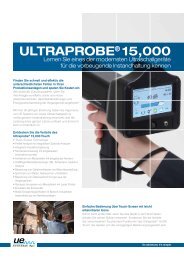
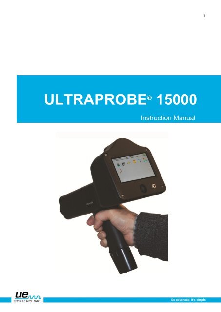
ULTRAPROBE ® <strong>15000</strong><br />
Instruction Manual
2<br />
Safety advisory<br />
Please read before using your instrument.<br />
Warning<br />
Improper use of your ultrasonic detector may result in death or serious injury. Observe all safety<br />
precautions. Do not attempt to make any repairs or adjustments while the equipment is operating. Be<br />
sure to turn off and LOCK OUT all electrical and mechanical sources before performing any<br />
corrective maintenance. Always refer to local guidelines for appropriate lockout and maintenance<br />
procedures.<br />
SAFETY PRECAUTION:<br />
Although your ultrasonic instrument is intended to be used while equipment is operating, the close<br />
proximity of hot piping, electrical equipment and rotating parts are all potentially hazardous to the<br />
user. Be sure to use extreme caution when using your instrument around energized equipment.<br />
Avoid direct contact with hot pipes or parts, any moving parts or electrical connections. Do not<br />
attempt to check findings by touching the equipment with your hands or fingers. Be sure to use<br />
appropriate lockout procedures when attempting repairs.<br />
Be careful with loose hanging parts such as the wrist strap or headphone cord when inspecting near<br />
moving mechanical devices since they may get caught. Don't touch moving parts with the contact<br />
probe. This may not only damage the part, but cause personal injury as well.<br />
When inspecting electrical equipment, use caution. High voltage equipment can cause death or<br />
severe injury. Do not touch live electrical equipment with your instrument. Use the rubber focusing<br />
probe with the scanning module. Consult with your safety director before entering the area and follow<br />
all safety procedures. In high voltage areas, keep the instrument close to your body by keeping your<br />
elbows bent. Use recommended protective clothing. Do not get close to equipment. Your detector will<br />
locate problems at a distance.<br />
When working around high temperature piping, use caution. Use protective clothing and do not<br />
attempt to touch any piping or equipment while it is hot. Consult with your safety director before<br />
entering the area.
3<br />
Table of Contents<br />
1. Introduction<br />
2. Ultraprobe Kit<br />
Basic Components 5<br />
A. Standard Plug-In Modules<br />
Scanning Module 6<br />
Contact Module 6<br />
LRM Long Range Module 6<br />
RAS-MT Magnetic Transducer 6<br />
RAM 7<br />
3. Accessories 7<br />
A. Standard Accessories 7<br />
Headset 7<br />
WTG-1 Warble Tone Generator 7<br />
Rubber Focusing Probe 7<br />
Stethoscope Extension Kit 7<br />
Battery 7<br />
BCH-15 Battery Charger 7<br />
Battery Charger Pod 7<br />
B. Optional Accessories 8<br />
CFM-15 8<br />
UWC-15 8<br />
DHC-2 Headphones 8<br />
TFSM 8<br />
TFCM 8<br />
UFMTG-1991 8<br />
WTG-2SP Warble Pipe Threaded Tone Generator 8<br />
BCH-WTG2 8<br />
HTS-15 8<br />
DISPLAY ICONS 9<br />
4. Overview 10<br />
A. Key Features 10<br />
Pistol Grip Housing 10<br />
On/Off/Suspend button 10<br />
SD Card 10<br />
Turn Off 10<br />
Suspend 10<br />
Trigger Switch 11<br />
Touch Screen Display 11<br />
Spectral Analysis Screen (FFT) 11<br />
Camera 11<br />
IR Thermometer 11<br />
Laser Pointer 12<br />
Battery 12<br />
Test Module Receptacle 12
4<br />
Setting up the Ultraprobe 15,000 12-13<br />
I. Turn on the Ultraprobe 15,000 12<br />
II. Home Screen 12-13<br />
Main Screen (dB) 12<br />
Setup Screen 12<br />
dB/Temp 12<br />
Valve (ABCD) Screen 13<br />
Route 13<br />
Setup Modes 13<br />
Functions 13<br />
Settings 13-14<br />
Operation 14<br />
Additional 14<br />
Applications 15<br />
Fields 15<br />
Viewing and Selecting Icons 15<br />
Using Screens 15-16<br />
Using Main Screen 16<br />
Using dB/Temp Screen 17<br />
Using Temp & Emissivity Screen 17<br />
Using Valve Screen 18<br />
Using Spectra (FFT) Screens 18<br />
Selecting Icons for Position on Displays 19<br />
Storing a Record 20<br />
Recording a Sound 20<br />
Capturing The Spectra Screen Image 20<br />
Entering Test Data 20<br />
View Record 21<br />
Viewing, Sorting a Route 21<br />
Camera 21<br />
Trigger Switch 22<br />
Quick Change Battery 22<br />
Wrist Strap 22<br />
Headset Jack 22<br />
Recharge Jack 22<br />
Charging Pod 22<br />
4. User Instructions 22<br />
Trisonic- Scanning Module 22<br />
Method of Airborne Detection 23<br />
Headset 23<br />
Rubber Focusing Probe 23<br />
Long Range Module 23<br />
Stethoscope Module 23<br />
Stethoscope Extension Kit 23<br />
RAM-MT Magnetic Transducer 24<br />
Charging The UP<strong>15000</strong> 24<br />
Warble Tone Generator 24<br />
Charging The Warble Tone Generator 24<br />
Helpful Hints 24<br />
Using the SD card 25<br />
Playing a Recorded Sound 25<br />
Auto Shutdown Battery Feature 25<br />
Resetting The On Board Computer 25<br />
Alarm Enable/Disable 25<br />
Ultraprobe 15,000 Specifications 26<br />
Instructions For Setting The Combination Lock On Carrying Case 27<br />
Index 28-30
Congratulations on your selection of the Ultraprobe 15,000. You are about to experience Ultrasound<br />
Condition Monitoring at its most advanced level. As you become more familiar with this amazing<br />
inspection system, we hope that you will begin to appreciate all that it can do to help with your predictive<br />
maintenance and energy conservation programs.<br />
1. INTRODUCTION<br />
Your Ultraprobe 15,000 is a versatile instrument with many features that will make your inspections<br />
easy, fast and accurate. As with any new instrument, it is important to review this manual before<br />
you begin inspections.<br />
5<br />
ULTRASOUND TECHNOLOGY TRAINING:<br />
Your Ultraprobe 15,000 has many applications ranging from leak detection and electrical inspection to<br />
mechanical analysis.<br />
It may be used to analyze sounds and data, view trends, or just identify a problem. How it is used is up<br />
to you. As you gain experience and learn how much you can do, you might want to extend your<br />
knowledge by enrolling in one of the many training courses offered by <strong>UE</strong> Training <strong>Systems</strong>, Inc.<br />
For more information about training opportunities:<br />
Go to: www.uesystems.com/training.as<br />
2. ULTRAPROBE 15,000 KIT<br />
WTG-1 Warble<br />
Tone<br />
Generator<br />
Headphones<br />
Trisonic<br />
Scanning<br />
Module<br />
Battery Recharger<br />
Battery & Pod<br />
Stethoscope<br />
Module<br />
Pistol-Grip<br />
Housing<br />
RAS/RAM<br />
Magnetic<br />
Transducer &<br />
Cable<br />
Rubber Focusing<br />
Probe<br />
Long Range<br />
Module<br />
Stethoscope Extension Kit
6<br />
STANDARD MODULES:<br />
I. PLUG-IN MODULES<br />
Trisonic TM Scanning<br />
Module<br />
TRISONIC SCANNING MODULE:<br />
This module is utilized to receive airborne ultrasound such as the ultrasounds emitted by<br />
pressure/vacuum leaks and electrical discharges. There are four prongs at the rear of the module. For<br />
placement, align the prongs with the four corresponding jacks in the front end of the pistol housing and<br />
plug in. The Trisonic TM Scanning Module has a phased array of three piezoelectric transducers to pick<br />
up the airborne ultrasound. This phased array focuses the ultrasound on one "hot spot" for directionality<br />
and effectively intensifies the signal so that minute ultrasonic emissions can be detected.<br />
Stethoscope (Contact)<br />
Module<br />
STETHOSCOPE (CONTACT) MODULE:<br />
This is the module with the metal rod. This rod is utilized as a "waveguide" in that it is sensitive to<br />
ultrasound that is generated internally such as within a pipe, bearing housing or steam trap. Once<br />
stimulated by ultrasound, it transfers the signal to a piezoelectric transducer located directly in the<br />
module housing. The module is shielded to provide protection from stray RF waves that have a tendency<br />
to effect electronic receiving and measurement. It is equipped with low noise amplification to allow for a<br />
clear, intelligible signal to be received and interpreted. For placement align the four prongs on the back<br />
with the corresponding receptacles in the front of the pistol and plug in.<br />
LRM-(LONG RANGE MODULE):<br />
A cone shaped scanning module that increases the detection distance above standard scanning<br />
modules. The LRM-15 is ideal for high voltage inspection and for locating leaks at great distances.<br />
Long Range Module
7<br />
RAM/RAS-MT REMOTE MAGNETIC TRANSDUCER<br />
The RAS/RAM-MT is a magnetically mountable contact probe with cable. The probe is applied to a test<br />
surface and the RAM (Remote Access Module) is plugged into the front end of the Ultraprobe.<br />
RAM/RAS-MT Magnetic Mount<br />
Transducer<br />
ACCESSORIES<br />
STANDARD ACCESSORIES<br />
HEADSET:<br />
This heavy duty headset is designed for use with or without a hardhat and can block out intense sounds<br />
often found in industrial environments so that the user may easily hear the sounds received by the<br />
ULTRAPROBE. In fact, these headphones provide over 23 dB of low frequency noise attenuation.<br />
WTG-1 WARBLE TONE GENERATOR:<br />
The WTG-1 Tone Generator is an ultrasound transmitter used to validate the sensitivity of an Ultraprobe<br />
before and at times after an inspection. For details on the Sensitivity Validation test, see Appendix A:<br />
Sensitivity Validation Test.(page 31) The Warble Tone generator may also be used for specialized tests<br />
such as when it is difficult to produce pressure or draw a vacuum floods an area with ultrasound which<br />
will flow through a (usually) large leak area. By scanning with the Trisonic Scanning Module, empty<br />
containers such as, bulkheads or hatches can be instantly checked for leakage.<br />
RUBBER FOCUSING PROBE:<br />
The Rubber Focusing Probe is a cone shaped rubber shield. It is used to block out stray ultrasound and<br />
to assist in narrowing the field of reception of the “Trisonic" Scanning Module.<br />
STETHOSCOPE EXTENSION KIT:<br />
This consists of three metal rods that will enable a user to reach up to 78 cm (31 additional inches) with<br />
the Stethoscope Module.<br />
BATTERY (2):<br />
This Ultraprobe 15,000 uses a lithium ion battery. A full charge will take about 4 hours, however you<br />
may charge the unit at any time for short intervals or for a longer period. If it is kept on charge over 4<br />
hours, there will be no harm to the battery.<br />
NOTE: When the effective battery charge is used up the instrument shuts down and a message to<br />
recharge the battery will be displayed in the display panel.<br />
BCH-10 BATTERY CHARGER:<br />
This is the battery charger for the UP15,000. It works with both 120 VAC, 60 Hertz and 240 VAC, 50<br />
Hertz and comes with multiple plug adaptors for different countries. The charging time is about 4 hours.<br />
There are two plugs: Black for the main pistol housing and Yellow for the WTG-1 Tone Generator.<br />
<strong>UE</strong>- BATTERY CHARGER POD:<br />
This is a Battery Recharge Pod docking station for charging Ultraprobe Batteries (Lithium Ion only). This<br />
pod will charge the standard batteries that come with the Ultraprobe 15,000 while removed from the<br />
metered pistol housing.
8<br />
B. OPTIONAL ACCESSORIES<br />
CFM-15:<br />
A scanning module used for close proximity low level leak detection in pressure and vacuum systems.<br />
UWC-15:<br />
The UWC-15, Ultrasonic Waveform Concentrator, substantially increases the detection distance. The<br />
UWC-15 is great for corona, tracking and arc detection at safe distances. Includes carrying case<br />
DHC-2:<br />
Headset for Standard Applications that do not require the use of a hard hat<br />
TFSM: Telescoping Flexible Scanning Module: A flexible scanning probe that is bent to<br />
accommodate odd scanning angles. The telescoping action helps scan hard to reach areas.<br />
TFCM: Telescoping Stethoscope (Contact) Module: A contact probe for structure borne inspection<br />
that can be extended for hard to reach areas.<br />
UFMTG-1991:<br />
The UFMTG 1991 is a multidirectional warble tone generator. It has a high power output with a circular<br />
transmission pattern of 360.<br />
WTG-2SP WARBLE PIPE THREADED TONE GENERATOR:<br />
A Warble Tone Generator that is used in test conditions where it is not possible to physically place the<br />
standard WTG-1 Warble Tone Generator, such as in pipes or in certain heat exchangers or tanks.<br />
Features: 1” NPT male threaded nipple with adapters for ¾” and ½” female nipple with a 10 turn<br />
amplitude adjustment dial. Metric adapters are also available.<br />
BCH-WTG:<br />
Optional 220 VAC @ 50 Hz charger for all Warble Tone Generators. The line input is 220 VAC @ 50Hz<br />
and the charging time is about 8 hours.<br />
HTS-15:<br />
Holster set for the UP15,000.
9<br />
DISPLAY ICONS:<br />
The main default<br />
screen.<br />
Spectral Analysis<br />
screen &<br />
function<br />
Opens Camera<br />
for photos<br />
View a specific<br />
historical record<br />
Main Screen<br />
displays dB<br />
Set up<br />
instrument<br />
functions<br />
Use to View<br />
image and take<br />
the photo<br />
Input additional test<br />
data to record<br />
Display<br />
\<br />
for dB<br />
and temperature<br />
Valve/Steam test<br />
display<br />
View your<br />
uploaded route<br />
Store your test<br />
data<br />
Turns off/on<br />
Temperature<br />
sensing<br />
Temperature<br />
display (no dB)<br />
Adjust Emissivity<br />
Exit screen<br />
Remove SD Card
10<br />
OVERVIEW<br />
KEY FEATURE<br />
PISTOL-GRIP HOUSING<br />
The pistol grip housing contains your operational features such as: On/Off button, Trigger Switch, Touch<br />
Screen, camera with flash, Infrared Thermometer, Laser pointer, Battery, and Test Module Receptacle.<br />
ON/OFF BUTTON<br />
Located on the back under the Display Panel, this must be pressed firmly to turn the instrument ON.<br />
NOTE: Be sure the SD card is inserted in the Ultraprobe 15,000 before turning on.<br />
1. TURN OFF:<br />
2. Press the On/Off button<br />
3. Touch the Off Box on the display screen<br />
SUSPEND<br />
In place of turning the instrument on and off in between short intervals of use, or to extend the use time<br />
on a battery (normally 4 hours of continuous use after a complete charge), put the instrument on<br />
SUSPEND. To do this:<br />
1. Press the On/Off button<br />
2. Touch the SUSPEND box on the display screen.<br />
3. RETURN TO OPERATION MODE (cancel the SUSPEND mode) :<br />
4. Touch the display screen and display will reopen.<br />
SD CARD AND SLOT<br />
The SD card is used to store all your inspection data and sounds. It will hold the test information for<br />
transfer to a computer that has Ultratrend DMS V 5.0 or higher installed.<br />
REMOVE SD CARD<br />
When removing the SD Card while the instrument is on , open the Home Screen and Select this icon.<br />
You will be prompted when to turn the instrument off.<br />
NOTE: Be sure the SD card is inserted in the Ultraprobe 15,000 before turning on<br />
ALWAYS turn the Ultraprobe 15,000 OFF before removing the SD card!
11<br />
TRIGGER SWITCH<br />
This has multiple functions. After the instrument has been turned on using the On/Off Button (above),<br />
Pull the trigger in while performing your tests. To hold a reading for storage or review, release the<br />
trigger. The trigger Switch is also used to turn on the laser pointer or the IR Thermometer when these<br />
features have been selected in the “Set Up Menu”.<br />
TOUCH SCREEN DISPLAY<br />
All your inspection functions can be controlled by just touching an icon, arrow or data box.<br />
SPECTRAL ANALYSIS SCREEN<br />
Select FFT (Spectra) display, Time Series display or dual display: Record and Play back sounds.<br />
CAMERA<br />
You may use the camera function to capture images of test points or items of interest that will be used<br />
in your reports.<br />
Laser Pointer<br />
Camera and<br />
Flash<br />
INFRARED THERMOMETER<br />
Screen displays image and test<br />
data<br />
This non-contact thermometer will measure the temperature of your test points. It can be used in the<br />
Temp screen and in the dB/Temp screen.<br />
Infrared<br />
Thermometer
12<br />
LASER POINTER<br />
The Laser pointer is a class II (for Europe) or a Class IIIa (elsewhere) type laser DO NOT POINT IT AT<br />
EYES. To activate it, enter the setup mode, select the “Oper” tab and look for Trigger Features. Touch<br />
the Trigger Features box. Then using the arrows, move up or down until Trig & Laser ON/OFF is shown.<br />
Touch the box to select and exit.<br />
BATTERY:<br />
Slide the Battery into the Handle until it “Clicks” in securely<br />
TEST MODULE RECEPTACLE:<br />
Plug in all test modules here.<br />
Battery Clip<br />
SETTING UP THE ULTRAPROBE 15,000<br />
Battery<br />
I. TURN ON THE ULTRAPROBE 15,000<br />
a. The instrument will not open without the SD card placed fully into the slot.<br />
b. To turn the instrument on, press and then release the ON/OFF button as shown.<br />
II. HOME SCREEN<br />
The Home Screen will display the Icons for operating your Ultraprobe 15,000.<br />
In order to select an operating screen, you must enter the Home Screen.<br />
The display screens in the Home Screen are:<br />
dB (Main Screen) This will display the test decibel and the test frequency<br />
Setup: This Icon will take you to the setup screen where you will configure the<br />
instrument to meet your test requirements<br />
dB/Temperature: This test screen displays decibel, frequency and temperature.
13<br />
ABCD (Valve Test Screen) This screen will only be displayed if the Valve or steam<br />
application has been selected in Setup/Applications. It will display the dB data for<br />
each of the four (A,B,C,D) test points and the frequency.<br />
Route: View your test route. The route is displayed in sequential order. Each record<br />
can be viewed by selecting (touching) the test number.<br />
Remove SD Card: You must use (touch) this icon BEFORE removing your SD Card.<br />
SET UP MODES & FEATURES<br />
Before using the instrument, become familiar with the various features and modes of operation. You<br />
may customize the instrument to meet your specific inspection demands. This is accomplished in the<br />
SETUP Mode.<br />
1. Turn the instrument on<br />
2. Locate the Setup icon on the Home Screen<br />
3. Touch the Icon to enter the Setup mode.<br />
4. NOTE: to select or change a setting; touch the selection box or circle on the screen. In some<br />
instances it will be necessary to use the UP/DOWN arrows on the right side of the screen to<br />
display your choices. Your Setup fields are as follows:<br />
5. “Functions”. Here you will be able to select:<br />
a. The inspection Module you will use (Ex: SCM, LRM etc.)<br />
b. Enable or disable the Alarm<br />
c. Record on Alarm. Have the instrument record a sound sample when the alarm level you set is<br />
exceeded<br />
d. Inspector identification<br />
6. “Settings” Your choices are:<br />
a. Set Record Time. Using the UP/DOWN selector arrows, the time for recording your sound<br />
samples can be selected. The selection will include a time value of from 5 seconds up to 30<br />
seconds. You may also select MANUAL. When MANUAL is selected, press the REC<br />
(recording) box in the Spectral Screen. To stop recording, Press STOP.<br />
b. Default Settings. When Yes is selected the instrument settings will change to the original<br />
settings as it came from the factory.<br />
c. Sensitivity Default: the user can select a sensitivity value so that every time the instrument is<br />
turned on for testing, that value will be the starting “high” level. For example, the default<br />
factory Sensitivity value is 70. In some routes this will be too high and to save time the<br />
inspector will set to a lower value for a starting point on that route.
d. Frequency Default: The default frequency from the factory is 40 kHz. If the Ultraprobe is to be<br />
used consistently at another frequency, set the default to that frequency. Every time the<br />
instrument is turned on, it will default to that selected frequency. For example, if most of the<br />
inspections are to be mechanical, the user might set the default frequency to 30 kHz.<br />
e. Turn off time: The Turn-off time can be set to 5, 10 or 15 minutes. Or it can be disabled. In<br />
disable, when the instrument is turned on, it will stay on until either it is turned off, set in<br />
suspend or the battery charge is depleted.<br />
f. WAV Sample Rate. When recording a sound for playback in the Spectral analysis screen or in<br />
<strong>UE</strong> Spectralyzer, the operator can adjust the sample rate. The default sample rate is 16,000.<br />
g. Instrument Setup: The factory default is Manual All adjustments are made by the inspector as<br />
he/she goes through the route. The Automatic setting is used after the initial baseline data has<br />
been uploaded to the Ultraprobe 15,000. In the Automatic setting the instrument will move<br />
sequentially from one test point to the next, and set itself for the original baseline setup, which<br />
will include the Frequency and Sensitivity for that point. For example, if the operator is testing<br />
bearings, the instrument will move from test point 1 to test point two and the if the baseline<br />
data was set at a sensitivity level of 43 with a frequency of 30 kHz, the instrument will<br />
automatically set for these parameters.<br />
Oper (Operation) The choices for this feature are:<br />
1. Display Response: This affects the movement of the intensity indicator. It may be set for Slow,<br />
Medium or Fast.<br />
2. Headphone Volume: There may be situations in which the sound level in the headphones is<br />
uncomfortably high and the sensitivity level must remain in a high level. To make this comfortable<br />
for the user, the volume of the headphones can be adjusted for 100% of volume to as low as 0%<br />
of volume.<br />
3. Trigger Features: The trigger is used to actively display a dB reading while pulled and freeze a dB<br />
reading when released. While the trigger is pulled the operator has the choice of: Trigger and<br />
Laser ON/OFF or Trigger ON, Laser always OFF. If Trigger and Laser On/Off is selected, every<br />
time the trigger is pulled, the Laser will be ON. When the Trigger is released, the Laser will turn<br />
OFF. If Trigger ON, Laser always OFF is selected, the Laser will always be off, even when the<br />
Trigger is pulled on for testing.<br />
4. Frequency Adjust: An inspector might want to be sure the frequency is not changed during a<br />
route. To lock the frequency, select No, to enable frequency tuning, select Yes.<br />
Additional: Selections here are:<br />
1. Upgrade program: Whenever there is an upgrade to the Ultraprobe 15,000 it may be downloaded<br />
off the web onto the SD card. Insert the SD card with the upgrade and use Upgrade Program.<br />
2. Restore List: All test information is set as a list in Ultratrend DMS, the standard operating<br />
software that accompanies the Ultraprobe. If list identification letters have been changed in<br />
Ultratrend DMS, they will be entered into the Ultraprobe. Restore lists will reset the Ultraprobe<br />
back to the original lists as set at the factory.<br />
3. Units: Set measuring units for Standard or Metric.<br />
4. Cal Due Date: This is set at the factory and reset every time the Ultraprobe is sent back after<br />
calibration.<br />
5. Set Time and Date: Set the time and date as appropriate for a specific area in which the<br />
instrument is used.<br />
14
Apps (Applications): Each application has unique data. When an application is selected the instrument<br />
will automatically set up specific fields that are unique to that application.<br />
The specific applications are:<br />
a. Generic<br />
b. Valves<br />
c. Bearing<br />
d. Electrical<br />
e. Steam<br />
f. Leak<br />
There is one other selection on the Apps page:<br />
Fields<br />
1. Fields: These are test information fields that can accompany test results. Select the specific fields<br />
for an application and then touch OK to set. While performing tests on a route after exiting setup,<br />
the operator can select the Input Data Icon to select any of the following (if they have been<br />
selected).<br />
a. Test Results<br />
b. Temperature<br />
c. Application<br />
d. Pressure<br />
e. Pipe Diameter<br />
f. Type<br />
15<br />
VIEWING AND SELECTING ICONS<br />
1. Icons may be viewed on any of the following display screens: Main, dB and Temperature, Valve<br />
and Temperature.<br />
2. Only two icons at a time may be shown continuously<br />
3. To view icons: touch the bottom of the screen.<br />
4. To view more icons, use the “left/right” arrows to move the icons on and off the screen<br />
5. To select an icon for continuous display and easy access on the screen:<br />
a. Touch the bottom of the screen to display the icons<br />
b. Use the left/right arrows until the icon you will use is displayed<br />
c. Touch the icon and slide it up to the middle of the left side of the display screen<br />
USING SCREENS:<br />
To use any of the screens:<br />
a. Turn on the Ultraprobe by pressing the ON button<br />
b. When the Home screen opens, select an Icon<br />
c. To use an operational screen such as “Main”, “dB/Temp”, “Temp”, or Valve, pull the trigger in<br />
and begin your inspection. If no or very little ultrasound is present of if the sensitivity value is<br />
too high for the test area, the dB will not show on the screen. 3 Dashed (---) lines will show.<br />
Adjust the “S” (Sensitivity value) by touching the Sensitivity box and then use the Up/DOWN<br />
arrows to move the S value up or down as needed.<br />
d. To freeze a reading for saving or observation, release the trigger.
16<br />
Home:<br />
When the Ultraprobe is turned on, the Home screen will be displayed. There are 4 icons shown: Main<br />
screen, Setup, dB and Temperature Screen, and Route. Should the Valve or Steam application be<br />
selected, the Valve icon (ABCD) will also be shown. Select one of the icons to enter and use the full<br />
features of the Ultraprobe 15,000.<br />
NOTE: To change from one operating screen (such as Main, dB/Temp or Valve) to another, you must<br />
return to the Home screen.<br />
1. Main: This screen will display the Record number, Decibel , Frequency, Sensitivity Level and an<br />
Intensity Level box. The Intensity Level box also acts as the Sensitivity Control. This will be explained<br />
below There are two control arrows on the right to be used to adjust or change the sensitivity,<br />
frequency, record number and emissivity.<br />
a. To change the Frequency: touch the kHz (frequency), when a highlight appears around the<br />
selected area then use the UP/DOWN arrows to adjust.<br />
b. To change the Sensitivity: touch the sensitivity value, when a highlight appears around the<br />
selected area then use the UP/DOWN arrows to change. You will see the change in the<br />
sensitivity value in the upper left of the screen. An alternative to using the arrows is to use the<br />
intensity level box, which uses a bar graph to indicate intensity. Tap the box in either the high<br />
(right) or low (left) area of the box until the Sensitivity value (S=) changes as needed).<br />
c. To change to different Record Number: touch the Record Number, when a highlight appears<br />
around the selected area then use the then use the UP/DOWN arrows to the desired location.<br />
d. To save the data, touch the bottom of the screen and locate the save icon, touch save, when<br />
prompted, touch yes to save.<br />
Viewing changes in Decibel Levels:<br />
To view decibel levels the Ultraprobe must be in the active scan mode. Pull the trigger in to activate the<br />
active scan mode. To freeze the data for storage, while pointing or touching the test point in the active<br />
mode, release the trigger. The data will be frozen on the screen until it is either stored or the Trigger is<br />
pulled in.<br />
Frequency<br />
Sensitivity value<br />
Record number<br />
Intensity level
17<br />
2. dB/Temp<br />
The decibel and temperature levels are shown in this screen.<br />
This screen will display the Record number, Decibel, Temperature, Frequency, Sensitivity Level and an<br />
Intensity Indicator box. The Intensity Indicator box also acts as the sensitivity control. There are two<br />
control arrows on the right to be used to adjust sensitivity and frequency.<br />
To freeze a temperature reading while continuing to test for decibel levels, tap the bottom of the display<br />
screen and use the LEFT/RIGHT arrows until the Temp on/off icon is shown. Touch the icon to turn off<br />
temperature sensing. When done, locate the Temp on/off icon and touch it again to turn the temperature<br />
reading function back on.<br />
3. Temp & Emissivity<br />
To test for Temperature only, select this screen. This is the only operating screen that can be accessed<br />
while in any of the other operating screens (Main, dB/Temp, Valve). It will only show the temperature.<br />
The Emissivity can be changed on this screen to adjust for a more accurate measurement. The default<br />
emissivity level is 95.<br />
To test for a temperature the instrument must be in the active scan mode. Pull the trigger in to activate<br />
the Active Scan Mode. To freeze the data for storage, while pointing or touching the test point in the<br />
active mode, release the trigger. The data will be frozen on the screen until it is either stored or the<br />
Trigger is pulled in.<br />
To adjust the Emissivity: touch the emissivity value and use the UP/Down arrows to reach the desired<br />
level<br />
a. To save the data, touch the bottom of the screen and locate the save icon, touch save, when<br />
prompted, touch yes to save.
18<br />
4. Valve/Steam (ABCD)<br />
To use the ABCD screen the VALVE or STEAM application must be selected in the setup mode. The<br />
ABCD icon will be displayed in the Home Screen. Go to the Home screen after selecting Valve in the<br />
setup application mode to use.<br />
This is the A,B,C,D screen. To enter the decibel values of test points A,B, C and D:<br />
a. Touch a valve test point A, be sure the instrument is in active test mode. Freeze the reading<br />
on the screen by releasing the trigger. tap the blank A lines and the dB reading will populate<br />
that section.<br />
b. Touch valve test point B, be sure the instrument is in active test mode. Freeze the reading on<br />
the screen by releasing the trigger, tap the blank B lines and the dB reading will populate that<br />
section.<br />
c. Touch valve test point C, be sure the instrument is in active test mode. Freeze the reading on<br />
the screen by releasing the trigger, tap the blank C lines and the dB reading will populate that<br />
section.<br />
d. Touch valve test point D, be sure the instrument is in active test mode. Freeze the reading on<br />
the screen by releasing the trigger, tap the blank D lines and the dB reading will populate that<br />
section.<br />
e. When done, touch the bottom of the screen and locate the save icon, touch save, when<br />
prompted, touch yes to save<br />
Spectra:<br />
This displays sound events in either an FFT screen, a Time Series Screen or Both screens at the same<br />
time. There are 6 buttons to use at the bottom of the displayed screen: START/STOP, PLAY,<br />
CAPTURE, REC, LEVELS, EXIT.<br />
a. LEVELS: To set up the Spectra screen touch/tap to enter LEVELS. The first screen has adjustments<br />
for setting the levels for the Spectra screen and for the Time Series Screen. There are 3<br />
adjustments:<br />
I. dB (decibel) scale. This can be used for both the Spectra and Time Series screens<br />
II.<br />
III.<br />
Frequency Scale, used in the Spectra Screen<br />
Time Scale, to adjust the ms or milliseconds
19<br />
IV.<br />
To exit back to the main Spectra screen, select Done<br />
V. Control: On the bottom right of the LEVELS screen is the Control box. Touch/tap to enter.<br />
The settings are:<br />
1. Screen views: Select FFT screen or Time Series Screen or view both on the same screen by<br />
selecting both.’<br />
2. Black /White plot: The default screen colors are blue and yellow, this can be changed to black<br />
and white. In instances where the screen image will be stored and printed, black and white<br />
might be selected to reduce the amount of ink used by a printer.<br />
3. CPM: instead of using the default Hertz, the scale can be set to read CPM (Cycles Per Minute)<br />
4. Log Scale<br />
5. Linear Scale<br />
6. Average<br />
7. Detect Peak<br />
b. Exit on Save Wave: After a sound sample has been recorded and saved, the Instrument will exit and<br />
return to the previously selected Operating Screens.<br />
c. When through adjusting the settings or to exit back to the Spectra Screen, select DONE<br />
d. STOP/START: When the Spectra screen opens it will start to display sounds sensed by the<br />
Ultraprobe, to stop this, touch/tap STOP, to start testing a sound sample, touch/tap START<br />
e. PLAY: To play a recorded sound back on the Ultraprobe and to view it while hearing it, touch/tap<br />
PLAY.<br />
f. CAPTURE: To capture the image of the screen, touch/tap CAPTURE. This image can be used<br />
in reports.<br />
g. REC ( Record), press this to record a sound sample. If in the MANUAL record mode, press the REC<br />
button. To stop in the Manual mode, press STOP. If the instrument has been set for a recording time<br />
in the Setup Mode, then just touch/tap and release the REC box.<br />
h. EXIT: exit to a previously selected screen.<br />
SELECTING ICONS FOR DISPLAY SCREEN<br />
NOTE: Only two icons at a time can be permanently displayed on an operational screen.<br />
1. Touch the bottom of an operational screen (Main, dB/Temp, Temp, Valve)<br />
2. Icons will appear<br />
3. Touch and drag the desired icon to the center of the left side of the screen
20<br />
STORING A RECORD<br />
1. Release the trigger to freeze the desired reading<br />
2. Locate the Store Record icon<br />
3. Touch/tap the Store icon.<br />
RECORDING A SOUND<br />
1. Locate and touch the Spectra (FFT) icon<br />
2. Touch/tap REC (Record)<br />
3. If the timed recording has been selected in the Settings/Set Record Time, the recording process<br />
will stop at the selected time<br />
4. If the Settings/Set Recording Time is in the Manual mode, to stop recording, touch/tap STOP.<br />
5. You will be asked: Save WAV File, Yes or No. To save, touch/tap Yes.<br />
6. To activate the Spectra screen when not in the REC Mode, touch/tap START to run the spectra (if<br />
STOP is shown the spectra screen is operating. To stop the spectra screen from running,<br />
touch/tap the STOP button). Every time the START button is tapped to run the spectra screen,<br />
you will be observing an averaging of the spectra on the screen. When it is stopped and<br />
restarted, the averaging process begins again.<br />
CAPTURING THE SPECTRA SCREEN IMAGE<br />
The Image of the selected spectra screen can be saved for viewing or entering in a report. To capture<br />
the screen image:<br />
1. Check the top left of the spectra screen to be sure you are at the desired Record number.<br />
2. Touch the CAPTURE tab<br />
3. Select Yes to save.<br />
ENTERING TEST DATA<br />
1. Locate the Input Data icon<br />
2. The Test data information will vary with each application. The title of the information will be shown<br />
in the upper left part of the screen<br />
3. To move from one selection to another, use the Left/Right arrows<br />
4. Touch/tap the screen of the desired data (ex: RPM or TEMP)<br />
5. Use the UP/DOWN arrows to enter the desired data<br />
6. These input data fields are set (and may be changed) in Ultratrend DMS,
21<br />
VIEW RECORD<br />
1. A record can be viewed in an operational screen. If the record number displayed is not the record<br />
you want to read:<br />
2. Touch/tap the Record box<br />
3. Use the UP/DOWN arrows to locate the desired record number<br />
4. Locate the View Record icon<br />
5. Touch/tap the icon<br />
6. When the data appears, you can scroll for all the stored data, touch the screen and drag your<br />
finger up or down.<br />
VIEWING A ROUTE<br />
1. Locate the Route icon by tapping the bottom of the display screen<br />
2. Touch/tap the Route icon<br />
3. Sorting Route Criteria: Using the SORT button, every time it is pressed it will rotate the sort. Sort<br />
options are: Record #, Low Status, High Status, OK Status or Not Updated.<br />
4. Reviewing a Photo: If a Y is shown in the P (Photo) column you may view the image by<br />
touching/tapping the Y. If multiple images are stored, view each by touching/tapping the display<br />
screen until you have viewed all images.<br />
5. Reviewing Wave Files: If a wave file is stored you may play either the baseline or current wave<br />
file. To play the baseline, touch/tap the Y in the W column and play.<br />
6. To open the record in the main dB display, touch/tap the Record #.<br />
Camera: To take a picture of a test point, touch the Camera icon. The Camera screen will show:<br />
1. Flash: On/Off: If you want the flash to be on, press ON, if you do not want the flash, press OFF.<br />
2. Zoom: If you want to zoom in or out ( up to 3X), tap the zoom box at the desired zoom location.<br />
The zoom level will be displayed to the left of the zoom box.<br />
3. To capture the image:<br />
a. Touch the View Photo icon and the image will be shown on the screen.<br />
b. Touch the image screen to capture the image.<br />
c. The image will appear with the test data.<br />
d. To save, press Save. You will be asked to confirm if you want to save the picture. IF you wish<br />
to save the picture, touch Yes. If you do not want to save the image at this point, press No. If<br />
you do not want to save the picture after you view it then press the Exit icon.
22<br />
TRIGGER SWITCH:<br />
The Trigger Switch is used to display the active dB reading. To observe the active dB reading, pull the<br />
trigger and hold it. For example, when scanning a leak or electric emission, pull the trigger in and scan<br />
the test area until you want to freeze the reading for storage or review. At that moment, release the<br />
trigger. To store the dB you have frozen on the screen, select the Save icon.<br />
The trigger can also be used to turn on the Laser Pointer. Note that the Laser Pointer will work only if it<br />
has been set to ON in the setup menu.<br />
QUICK CHANGE BATTERY:<br />
To insert the battery, align the battery with the handle (arrow pointing towards the trigger) and push in<br />
until the clips snap in place. To remove the battery, push firmly on the battery clips with the fingers of<br />
one hand while holding your other hand under the handle to catch the released battery.<br />
WRIST STRAP:<br />
To protect the instrument, against being dropped accidentally, use the wrist strap.<br />
HEAD SET JACK:<br />
This is where you plug in the headset. Be sure to plug it in firmly until it clicks.<br />
RECHARGE JACK :<br />
This Jack receives the plug from the recharger. The recharger is designed to plug into a standard<br />
electrical receptacle.<br />
CHARGING POD<br />
Keep a backup battery fully charged using the Charging Pod. This is a battery recharge docking station<br />
for charging Ultraprobe Batteries (Lithium Ion). This pod will charge the standard batteries that come<br />
with the Ultraprobe 15,000 while removed from the metered<br />
USERS INSTRUCTIONS<br />
TRISONIC TM SCANNING MODULE:<br />
1. This module plugs into the front end of the instrument.<br />
2. Align the pins located at the rear of the module with the four jacks in the front end of the<br />
Metered Pistol Housing (MPH) and plug in.<br />
3. For general use position the frequency selection to 40 kHz.<br />
4. Start to scan the test area.
METHOD OF AIRBORNE DETECTION:<br />
The method of air borne detection is referred to as "Gross to Fine". Start at maximum sensitivity<br />
(S=70), constantly reducing the sensitivity and following the bar graph amplitude display to the loudest<br />
point. If there is too much ultrasound in the area, reduce the sensitivity, place the RUBBER FOCUSING<br />
PROBE (described below) over the scanning module and proceed. Every time the sound level rises to a<br />
point where it is difficult to follow, reduce the sensitivity again and again until you are able to follow the<br />
test sound to its' loudest point.<br />
HEADSET:<br />
The DHC2-HH headphones are designed to be worn with hard hats. To use, simply plug the headset<br />
cord into the headset Jack on the pistol housing, and place the headphones over your ears.<br />
RUBBER FOCUSING PROBE :<br />
To use, simply slip it over the front of the scanning module or the contact(stethoscope) module.<br />
NOTE: To prevent damage to the module plugs, always remove the module BEFORE attaching and/or<br />
removing the Rubber Focusing Probe.<br />
LONG RANGE MODULE (LRM)<br />
1. This module plugs into the front end of the instrument.<br />
2. Align the pins located at the rear of the module with the four jacks in the front end of the Metered<br />
Pistol Housing (MPH) and plug in.<br />
3. For general use position the frequency selection to 40 kHz.<br />
4. Start to scan the test area.<br />
STETHOSCOPE MODULE:<br />
1. Align the pins located at the rear of the module with the four jacks in the front end of the Metered<br />
Pistol Housing (MPH) and plug in.<br />
2. Touch test area.<br />
As with the SCANNING MODULE, go from the "gross" to the "fine". Start at maximum sensitivity (S=70)<br />
on the Sensitivity Selection dial and proceed to reduce the sensitivity until a satisfactory sound level is<br />
achieved. At times it may be necessary to utilize the STETHOSCOPE MODULE with the sensitivity level<br />
at or near maximum. Occasionally when in this situation stray ultrasound may interfere with clear<br />
reception and be confusing. If this occurs, place the RUBBER FOCUSING PROBE over the<br />
Stethoscope probe to insulate against the stray ultrasound.<br />
STETHOSCOPE EXTENSION KIT:<br />
1. Remove the Stethoscope Module from the Metered Pistol Housing.<br />
2. Unscrew the aluminum rod in the Stethoscope Module.<br />
3. Look at the thread of the rod you just unscrewed and locate a rod in the kit that has the same size<br />
thread this is the "base piece".<br />
4. Screw the Base Piece into the Stethoscope Module.<br />
5. If all 78cm (31") are to be utilized, locate the middle piece. (This is the rod with a female fitting at<br />
one end) and screw this piece into the base piece.<br />
6. Screw third "end piece" into middle piece.<br />
7. If a shorter length is desired, omit step 5 and screw "end piece" into "base piece".<br />
23
24<br />
RAM/RAS-MT<br />
Align the pins located at the rear of the module with the four jacks in the front end of the Metered Pistol<br />
Housing (MPH) and plug in. Place the magnetic transducer on the test location.<br />
TO CHARGE THE UP<strong>15000</strong>:<br />
1. Plug recharger cable into recharger jack on the UP<strong>15000</strong> and then plug the recharger into a wall<br />
receptacle.<br />
2. Make sure that the LED on the charger is blinking when recharging.<br />
3. The LED remains solid when the battery is charged. The instrument may stay connected to the<br />
charger without damaging the battery. Charge time is approximately 4 hours.<br />
4. WARNING: Use the supplied <strong>UE</strong> <strong>Systems</strong> recharger (BCH-10L) only. Use of unauthorized<br />
rechargers will void the warranty and may degrade or damage the battery.<br />
WARBLE TONE GENERATOR/SENSITIVITY VALIDATION UNIT (<strong>UE</strong>-WTG-1):<br />
The Tone Generator has two functions.<br />
Sensitivity Validation:<br />
This is a procedure that should be incorporated BEFORE you perform any test with your Ultraprobe. It<br />
provides assurance that your instrument is working properly to provide repeatable, reliable results for<br />
any of your inspections routines. This is a procedure that is recommended for any Predictive<br />
Maintenance instrument you may use If performed regularly it will promote accuracy and test reliability<br />
throughout your PdM program.<br />
For detailed instructions, refer to Appendix A: “Sensitivity Validation Procedure”<br />
As a method for locating large leaks when it is difficult to produce pressure or vacuum. To<br />
perform this test:<br />
1. Turn Tone Generator on by selecting either "LOW" for a low amplitude signal or "HIGH" for high<br />
amplitude. When the Tone Generator is on, a red light (located below the recharge jack in the<br />
front) flickers.<br />
2. Place the Warble Tone Generator within the test item/container and seal or close it. Then scan<br />
the suspect areas with the Trisonic Scanning Module in the Ultraprobe and listen for where the<br />
"warble" ultrasound penetrates.<br />
TO CHARGE THE WARBLE TONE GENERATOR/SENSITIVITY VALIDATION UNIT:<br />
1. Plug recharger cable into recharger jack on the Warble Tone Generator and then plug the<br />
recharger into a wall receptacle.<br />
2. Make sure that the LED on the charger is lit when recharging.<br />
3. The LED turns OFF when the battery is charged.<br />
HELPFUL HINTS:<br />
Before you begin your inspection activities, it is suggested that you review the applications section to<br />
become familiar with the basic inspection methods.
25<br />
USING THE SD CARD<br />
NOTE: Be sure the SD card is inserted in the Ultraprobe 15,000 before you begin testing.<br />
PLAYING RECORDED SOUNDS:<br />
You may review baseline sounds that have been uploaded to your Ultraprobe and compare them to<br />
currently recorded sounds.<br />
1. Open Routes and select the record with the baseline sound. If the baseline sound has been<br />
uploaded it will be noted with a “Y” in the Wave (“W”) column.<br />
2. Touch the “Y” and the Spectra screen will open and begin to play the sound.<br />
a. To compare with a recently recorded sound for the selected route number:<br />
1. Exit the Spectra Screen, open an operating screen ( Main or Temp/dB),<br />
2. Make sure the screen displays the appropriate record number in your route<br />
3. Reopen Spectra<br />
4. Select PLAY<br />
5. A window will open displaying two wave files: one with a prefix of BL is the Baseline wav file<br />
the other with a prefix of SA is the current wav file<br />
6. Touch the Next button to move to the wav file you want to play<br />
7. To play, touch the Select button<br />
AUTO-SHUTDOWN BATTERY FEATURE<br />
The Ultraprobe 15,000 is equipped with an auto-shutdown feature when the battery energy is depleted.<br />
A message in the Display Panel will read “RECHARGE BATTERY”, and the instrument will go into a<br />
“sleep” mode. The instrument will automatically store all records onto the SD card at shutdown. After the<br />
battery is replaced with a freshly charged battery, turn the Ultraprobe 15,000 back on and continue your<br />
testing<br />
RESETTING THE ON BOARD COMPUTER:<br />
There is no reset switch on the instrument. Should it be necessary to reset the instrument:, Enter<br />
SETUP Mode touch/tap the tab “OPERATIONS”, touch/tap DEFAULT SETTINGS) and choose the<br />
YES. WARNING: Selecting Default Settings erases all records stored in the instrument.<br />
If that does not work, disconnect the battery for one (1) minute and then reconnect the battery.<br />
ALARM ENABLE/DISABLE<br />
To enable or disable an alarm level: (the alarm levels are set in Ultratrend DMS and sent to the<br />
instrument.<br />
1. Enter Setup , Functions<br />
2. Select Alarm Enable or Disable.<br />
3. When Alarm level is exceeded the display will change color and, if selected the sound will be<br />
recorded.
26<br />
Ultraprobe® 15,000 Touch Specifications<br />
Construction<br />
Circuitry<br />
Frequency Range<br />
Hand-held pistol type made with coated aluminum and ABS plastic<br />
Solid State Analog and SMD Digital Circuitry with temperature<br />
compensation and true RMS conversion<br />
20 kHz to 100 kHz (tunable in 1 kHz increments)<br />
Response Time<br />
27<br />
INSTRUCTIONS FOR SETTING COMBINATION ON CARRYING CASE<br />
The combination is factory set at ,0-0-0,,<br />
Setting your personal combination:<br />
1. Open the case. Looking at the back of the lock inside the case you will<br />
see a change lever. Move this change lever to the middle of the lock so<br />
that it hooks behind the change notch (picture 1 ).<br />
2. Now set your personal combination by turning the dials to the desired<br />
combination (i.e. birthday, phone no. etc.)<br />
3. Move the change lever back to the normal position (picture 2).<br />
4. To lock, rotate one or more dials. To open the lock, set your personal<br />
combination.
28<br />
INDEX<br />
ABCD (Valve) Screen 18<br />
Accessories 7<br />
Additional 14<br />
Alarm Enable/Disable 25<br />
Applications 15<br />
Auto Shutdown Battery Feature 25<br />
Basic Components 6<br />
Battery 7<br />
Battery Charger Pod 7<br />
BCH-15 Battery Charger 7<br />
BCH-WTG2 8<br />
Camera 11<br />
Camera 21<br />
Capturing The Spectra Screen Image 20<br />
CFM-15 8<br />
Charging Pod 22<br />
Charging The UP<strong>15000</strong> 24<br />
Charging The Warble Tone Generator 24<br />
Contact Module 6<br />
dB/Temp 13<br />
DHC-2 Headphones 8<br />
Entering Test Data 20<br />
FFT Display 9<br />
Fields 13<br />
Functions 15<br />
Headset 7<br />
Headset 23<br />
Headset Jack 22<br />
Helpful Hints 25<br />
Home Screen 12<br />
HTS-15 8<br />
ICONS 9<br />
Instructions For Setting The Combination Lock On<br />
Carrying Case 27
29<br />
Introduction 5<br />
IR Thermometer 11<br />
Key Features 9<br />
Laser Pointer 12<br />
LRM Long Range Module 6<br />
Main Screen (dB) 12<br />
On/Off button 10<br />
Operation 14<br />
Optional Accessories 8<br />
Overview 10<br />
Pistol Grip Housing 10<br />
Playing/Recording Sounds 24<br />
Quick Change Battery 21<br />
RAM/RAS-MT 7<br />
Recharge Jack 22<br />
Recording a Sound 19<br />
Resetting The On Board Computer 25<br />
Route 13<br />
Rubber Focusing Probe 7<br />
Scanning Module 6<br />
SD Card 10<br />
Selecting Icons for Position on Displays 19<br />
Setting up the Ultraprobe 15,000 12<br />
Settings 13<br />
Setup Modes 13<br />
Setup Screen 13<br />
Standard Accessories 7<br />
Standard Plug-In Modules 6<br />
Stethoscope Extension Kit 7<br />
Storing a Record 19<br />
Suspend 10<br />
Test Module Receptacle 12<br />
TFCM 8<br />
TFSM 8
30<br />
Touch Screen Display 11<br />
Trigger Switch 11<br />
Trisonic- Scanning Module 6<br />
Turn Off 10<br />
Turn on the Ultraprobe 15,000 11<br />
UFMTG-1991 8<br />
Ultraprobe 10,000 Specifications 26<br />
Ultraprobe Kit 5<br />
Using dB/Temp Screen 16<br />
Using Main Screen 16<br />
Using Screens 15<br />
Using Spectra (FFT) Screens 18<br />
Using Temp & Emissivity Screen 17<br />
Using the SD card 10 & 25<br />
Using Valve Screen 18<br />
UWC-15 8<br />
Valve (ABCD) Screen 18<br />
View Record 21<br />
Viewing a Route 21<br />
Viewing and Selecting Icons 15<br />
WTG-1 Warble Tone Generator 7<br />
WTG-2SP Warble Pipe Threaded Tone Generator 8
31<br />
APPENDEX A<br />
Sensitivity Calibration<br />
Ultrasonic Tone Generator Method<br />
Ultraprobe <strong>15000</strong><br />
It is advisable to check the sensitivity of your instrument before proceeding with your inspection. To<br />
assure reliability keep a record of all your sensitivity validation tests and be sure to keep your<br />
Warble Tone Generator charged.<br />
Procedure:<br />
1. Create a chart or use the one below:<br />
Sensitivity Validation<br />
Scanning Module Date Serial #\ TG setting Frequency DB<br />
Contact Module Date Serial # TG setting Frequency DB<br />
A. For the Scanning Module, insert it into the front end of the instrument.<br />
2. Select 40 kHz as the test frequency and note “40” in the Frequency box for the Scanning<br />
Module in the Sensitivity Validation Chart<br />
3. Plug in the Headphones and adjust the ear pieces so that they are opened up and place<br />
them on the test table<br />
4. In your kit select the longest of the Stethoscope extension probe rods.<br />
5. Place an “L” in the Rod used box of your Sensitivity Validation Chart<br />
6. Place the Tone generator on the side with the front facing you.
32<br />
7. Place the rod in the middle of the transducer are (as above)<br />
8. Select a volume level on the Warble Tone Generator (Low or High).<br />
9. Note the level (L or H) in the TG box of the Sensitivity Validation chart.<br />
10. Turn the Ultraprobe 15,000 on its’ side so that it will rest flat on the test table with the<br />
handle facing you and the Scanning Module facing the Tone Generator.<br />
11. Slide the Ultraprobe gently so that the front faceplate touches the Rod and that the rod is<br />
touching the face plate while touching the side of the Scanning Module. Align the<br />
Scanning<br />
Module so that the center of the module is facing the center of the Tone Generator Transducer<br />
(see below).<br />
12. Adjust the sensitivity until the intensity bar graph is at mid-line and displays the decibel<br />
level.<br />
13. Note and record the decibel reading in the dB box of your Sensitivity Validation chart.<br />
B. For the Contact (Stethoscope) Module, insert the Module into the Front End of the Instrument:<br />
1. Select 40 kHz as the test frequency and note “40” in the Frequency box forthe<br />
Contact Module in the Sensitivity Validation Chart<br />
2. Plug in the Headphones and adjust the ear pieces so that they are opened up and<br />
place them on the test table<br />
3. Place the Warble Tone Generator flat facing up with the recharge jack facing you<br />
at 90º.
33<br />
4. Select a volume level on the Warble Tone Generator (High or Low).<br />
5. Note the level (H or L) in the TG box of the Sensitivity Validation chart.<br />
6. With the handle facing you, align the tip of the contact probe with the recharge jack<br />
and allow the probe to rest on the jack. DO NOT PRESS DOWN! (NOTE: NEVER<br />
USE THE ALUMINUM EXTENSION PROBE RODS THEY WILL SHORT OUT<br />
THEBATTERY OF THE WTG)<br />
7. Adjust the sensitivity until intensity bar graph is at mid-line<br />
8. Note and record the decibel in the dB box of your Sensitivity Validation chart.<br />
For all tests:<br />
Whenever you perform a Sensitivity Validation Test, review the data in the Sensitivity Validation<br />
chart<br />
and repeat the test using the same rod/module, frequency, and Warble Tone Generator volume<br />
setting.<br />
Look for a change in the decibel reading. A change of greater than 6 dB will indicate a problem.
34<br />
Need further support?<br />
Want information regarding products or training?<br />
Contact :<br />
<strong>UE</strong> <strong>Systems</strong> Europe, Windmolen 22, 7609 NN Almelo (NL)<br />
e: info@uesystems.eu w: www.uesystems.eu<br />
t: +31 (0)548 659-011 f: : +31 (0)548 659 010<br />
www.uesystems.eu