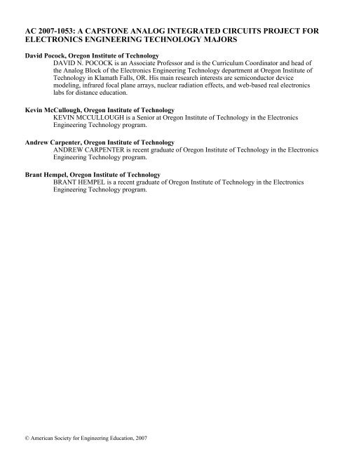
ac 2007-1053: a capstone analog integrated circuits ... - Icee.usm.edu
ac 2007-1053: a capstone analog integrated circuits ... - Icee.usm.edu
ac 2007-1053: a capstone analog integrated circuits ... - Icee.usm.edu

Create successful ePaper yourself
Turn your PDF publications into a flip-book with our unique Google optimized e-Paper software.
AC <strong>2007</strong>-<strong>1053</strong>: A CAPSTONE ANALOG INTEGRATED CIRCUITS PROJECT FOR<br />
ELECTRONICS ENGINEERING TECHNOLOGY MAJORS<br />
David Pocock, Oregon Institute of Technology<br />
DAVID N. POCOCK is an Associate Professor and is the Curriculum Coordinator and head of<br />
the Analog Block of the Electronics Engineering Technology department at Oregon Institute of<br />
Technology in Klamath Falls, OR. His main research interests are semiconductor device<br />
modeling, infrared focal plane arrays, nuclear radiation effects, and web-based real electronics<br />
labs for distance <strong>edu</strong>cation.<br />
Kevin McCullough, Oregon Institute of Technology<br />
KEVIN MCCULLOUGH is a Senior at Oregon Institute of Technology in the Electronics<br />
Engineering Technology program.<br />
Andrew Carpenter, Oregon Institute of Technology<br />
ANDREW CARPENTER is recent graduate of Oregon Institute of Technology in the Electronics<br />
Engineering Technology program.<br />
Brant Hempel, Oregon Institute of Technology<br />
BRANT HEMPEL is a recent graduate of Oregon Institute of Technology in the Electronics<br />
Engineering Technology program.<br />
© American Society for Engineering Education, <strong>2007</strong>
A Capstone Analog Integrated Circuits Project for Electronics<br />
Engineering Technology Majors<br />
Abstr<strong>ac</strong>t<br />
Oregon Institute of Technology offers a B<strong>ac</strong>helor of Science in Electronics Engineering<br />
Technology that includes a senior level <strong>capstone</strong> course in <strong>analog</strong> <strong>integrated</strong> circuit design. This<br />
course includes a two credit hour (six cont<strong>ac</strong>t hours per week) laboratory in which students<br />
would normally perform six to eight individual “canned” experiments. Recently the author has<br />
re-structured the laboratory to become a term-long group project in the area of <strong>analog</strong> <strong>integrated</strong><br />
<strong>circuits</strong>. This paper describes the results of one of these team projects.<br />
Introduction<br />
The objective of this <strong>capstone</strong> course is to expose senior EET majors to the design process for<br />
<strong>analog</strong> <strong>integrated</strong> <strong>circuits</strong> by working as a member of a design team. Upon completion of this<br />
course, a student will have been exposed to the processes of working in a team, picking an idea,<br />
researching the topic, formulating a design, dividing up the tasks, generating a sch<strong>edu</strong>le, writing<br />
periodic progress reports, doing hand calculations and computer simulations, breadboarding<br />
individual stages, integrating the entire system, and presenting their results in a formal oral<br />
presentation and a final written report; including a fully operational demonstration. 1<br />
Requirements<br />
The instructor stipulates that the design must be DC coupled (i.e. no coupling or bypass<br />
cap<strong>ac</strong>itors), that the breadboard must use matched transistor ICs such as the CA3046 and<br />
CA3096, and that the circuit should use current-mirror biasing, <strong>ac</strong>tive loads, a differential input<br />
stage, a gain stage, a level shifter, and an output stage, if applicable. The major building blocks<br />
are npn and pnp bipolar junction transistors, but MOSFETs are also allowed. 2<br />
Summary<br />
To date, student teams have successfully demonstrated fully operational designs in breadboard<br />
for such <strong>analog</strong> <strong>circuits</strong> as operational amplifiers, instrumentation amplifiers, voltage<br />
comparators, digital-to-<strong>analog</strong> converters, <strong>analog</strong>-to-digital converters, sample-and-hold<br />
amplifiers, voltage controlled oscillators, phase-locked loops, a frequency synthesizer, and<br />
Costas loops. This paper summarizes the results of a team that developed a phase-locked-loop<br />
from the transistor level. The students worked harder and learned more compared to the canned<br />
lab appro<strong>ac</strong>h, while the instructor worked less and felt very proud of his students.
Purpose and Objectives<br />
The concept of a phase-locked loop was first developed in the 1930s. It has since been used in<br />
communications systems of many types. A phase-locked loop is a closed-loop feedb<strong>ac</strong>k control<br />
system, and its main purpose is to maintain a generated signal in a fixed phase relationship to a<br />
reference signal. Until recently, however, phase-locked loop systems have been too costly and<br />
complex for most consumer and industrial markets where other appro<strong>ac</strong>hes were more<br />
economical. However, the PLL is particularly useful to monolithic construction, and <strong>integrated</strong>circuit<br />
phase-locked loops can now be fabricated at very low cost. Their use has become<br />
attr<strong>ac</strong>tive for many applications including FM demodulators, stereo demodulators, tone<br />
detectors, frequency synthesizers, and the like.<br />
The objective of this lab is to design and construct a phase-locked loop using only discrete<br />
components. The circuit must perform up to specific design requirements which are reasonable<br />
for PLL systems. The timeline for this project is less than 10 weeks.<br />
Materials & Equipment<br />
• CA3046 NPN Transistor array p<strong>ac</strong>kages<br />
• 6.2V Zenor Diodes<br />
• Various Resistors<br />
• Protoboard<br />
• Agilent 33220A Function Generator<br />
• Hewlett P<strong>ac</strong>kard 54600B Oscilloscope<br />
Theory of Operation<br />
A block diagram of a phase-locked loop system is shown below.<br />
Input<br />
Signal<br />
Phase<br />
Detector<br />
Loop<br />
Filter<br />
Amplifier<br />
Output<br />
Voltage-controlled<br />
Oscillator<br />
Figure 1: Basic Phase-Locked Loop System.<br />
The basic elements of the PLL system are a phase detector, a loop filter, an amplifier, and a<br />
voltage-controlled oscillator (VCO). The VCO is simply an oscillator whose frequency is<br />
proportional to an externally applied voltage. When the loop is locked on an input signal, the<br />
VCO frequency is ex<strong>ac</strong>tly equal to the input signal’s frequency. The output of the VCO is a
square wave regardless of what type of wave the input is. The phase detector basically works<br />
like a mixer which produces the sum and the difference frequencies between the input signal and<br />
the VCO signal. These signals are passed through a low pass filter which generates a dc or lowfrequency<br />
signal proportional to the difference in phase between the two input signals. This is<br />
lastly fed into the VCO input which produces a correction frequency in order to maintain lock<br />
with the input frequency.<br />
Proc<strong>edu</strong>res<br />
The students constructed e<strong>ac</strong>h of the following functional sections in the order listed. E<strong>ac</strong>h<br />
section was tested and proper operation was confirmed before proceeding to the following<br />
section.<br />
Students were reminded that it is important when constructing these <strong>circuits</strong> on a breadboard to<br />
keep in mind certain layout considerations. Try to keep components as close as possible to<br />
minimize the length of connecting wires. This will improve the overall frequency response of<br />
the circuit. Keep wires neat and low to the board as well. This will keep the design cleaner and<br />
easier to troubleshoot when necessary. Use bypass cap<strong>ac</strong>itors <strong>ac</strong>ross the supply voltages. For<br />
high frequency or cap<strong>ac</strong>itance sensitive oscilloscope measurements, use the x10 setting on the<br />
probe. Also, e<strong>ac</strong>h CA3046 transistor array p<strong>ac</strong>kage has a substrate pin on the emitter of Q5<br />
which must be tied to the lowest voltage seen by the p<strong>ac</strong>kage.<br />
Bias Circuitry Design<br />
The bias circuitry essentially creates the controlled voltage and current sources which provide<br />
bias and power to e<strong>ac</strong>h of the functional components. This was constructed and verified first<br />
because its operation can easily be tested and is not dependent on any other functional section.<br />
Also, to test e<strong>ac</strong>h of the other sections, various sources of bias current and voltage were needed<br />
from this circuitry.<br />
Students designed and constructed the circuit as shown in the following Figure 2. They used<br />
+20V for the VCC supply.<br />
When testing the above circuit alone, 10k ohm resistors were used as passive loads for the<br />
current sources. E<strong>ac</strong>h bias voltage and current were measured and came within +/- 10% of the<br />
following values:<br />
VCO_Pwr = 7.0 V<br />
PD_Pwr = 13.0 V<br />
PD_VBias = 4.0V<br />
PD_IBias = 600 µA<br />
CS_IRef = 500 µA<br />
VCO_IRef1 = 400 µA<br />
VCO_IRef2 = 400 µA<br />
VCO_IRef3 = 400 µA<br />
VCO_IRef4 = 400 µA
VCC<br />
R15<br />
5.3k<br />
U1(1)<br />
VCC<br />
Q20<br />
U1(3)<br />
VCC<br />
Q21<br />
U1(4)<br />
VCC<br />
Q22<br />
D7 D1N5234<br />
D9 D1N4148<br />
R17<br />
2.2k<br />
D13 D1N5234<br />
VCO_Pwr<br />
PD_Pwr<br />
R23<br />
10k<br />
D8 D1N5234<br />
D10 D1N4148<br />
0<br />
VCC<br />
D11 D1N5234<br />
D12 D1N4148<br />
0<br />
U2(1)<br />
Q24<br />
R18<br />
3.6k<br />
R19<br />
6.4k<br />
PD_IBias<br />
U2(3)<br />
Q23<br />
VCC<br />
U1(5)<br />
Q25<br />
R22<br />
5.6k<br />
PD_VBias<br />
20v<br />
V1<br />
R20<br />
330<br />
R21<br />
330<br />
0<br />
0<br />
0<br />
Figure 2: Bias circuitry schematic for various bias currents and voltages.<br />
0<br />
Q26<br />
U2(4)<br />
R16<br />
1.15k<br />
0<br />
CS_IRef VCO_IRef 1 VCO_IRef 2 VCO_IRef 3 VCO_IRef 4<br />
U3(2) U3(3) U3(4) U4(3) U4(4)<br />
Q28 Q29 Q30 Q31 Q32<br />
R24<br />
1.15k<br />
R25<br />
1.5k<br />
R26<br />
1.5k<br />
R27<br />
1.5k<br />
R28<br />
1.5k<br />
0 0 0 0 0
Voltage Controlled Oscillator<br />
The voltage controlled oscillator that the students built is shown in Figure 3. The (VCO)<br />
frequency is set by the value of the cap<strong>ac</strong>itor C1 and the sum of the currents that<br />
charge/discharge the cap. VCO_IRef1 and VCO_IRef4 are fixed at 400µA while the variable<br />
current sources VCO1 and VCO2 contribute up to 250 µA on e<strong>ac</strong>h side. This creates an<br />
effective current range of 400 µA to 650 µA to charge or discharge the cap<strong>ac</strong>itor. Obviously,<br />
larger currents charge and discharge the cap<strong>ac</strong>itor faster and result in a higher output frequency.<br />
The mechanism which controls the switching point of this circuit is R1 and Q1. The opposite<br />
side with R2 and Q4 is symmetric and operates identically except during the opposite half of<br />
e<strong>ac</strong>h cycle. When enough current is drawn through the resistor, a sufficient voltage is created to<br />
turn on Q1. With Q1 on, enough current can flow to turn on Q5 and Q8. With Q8 on, the<br />
cap<strong>ac</strong>itor begins to charge at the rate of current from VCO_IRef1+VCO1. Eventually the<br />
voltage at the emitter of Q8 becomes higher than three V BE drops from the VCO_Pwr voltage<br />
and the transistor turns off. At the same time the voltage on the other side of the cap<strong>ac</strong>itor has<br />
dropped below three V BE drops and that side turns on which begins charging the cap<strong>ac</strong>itor in the<br />
opposite direction. The currents drawn from VCO1 and VCO 2 are controlled by a voltage,<br />
which is what makes this a voltage controlled oscillator.<br />
The circuit as shown in Figure 3 was constructed. Necessary connections to the previously<br />
created current and voltage bias circuitry were made. The output at VCO3 or VCO4 was a 50%<br />
duty cycle square wave at around 100 kHz if VCO1 and VCO2 were not connected. The freerunning<br />
frequency was higher due to the addition of these variable current sources.<br />
The equation for finding the VCO operating frequency is,<br />
f<br />
IC<br />
=<br />
4*C *V<br />
1 BE(on)<br />
where I C is the sum of the currents which charge or discharge one side of the cap<strong>ac</strong>itor, C 1 is the<br />
value of the cap<strong>ac</strong>itor, and V BE(on) is about 0.65V.<br />
This equation is also used to calculate the VCO free-running frequency where I C is specifically<br />
400 µA + ½ (VCO1 max ), and VCO1 max = VCO2 max = ½ (CS_IRef) from Figure 2.
VCO_Pwr<br />
R1<br />
3.5k<br />
Q1<br />
U5(1)<br />
VCC<br />
Q4<br />
U5(3)<br />
R2<br />
3.5k<br />
U5(4)<br />
Q5<br />
Q6<br />
U6(1)<br />
V<br />
VCO3<br />
VCO4<br />
U6(3)<br />
Q7<br />
Q8<br />
U6(4)<br />
VCO_IRef 2<br />
VCO_IRef 3<br />
C1<br />
1.52nF<br />
VCO_IRef 1<br />
VCO1<br />
Figure 3: VCO Schematic<br />
VCO2<br />
VCO_IRef 4<br />
Phase Comparator<br />
The phase comparator, shown in Figure 4, can be thought of as a high-gain mixer. Essentially,<br />
the input signal is exclusive OR’d (XOR) with the VCO signal so that the result is a square wave<br />
with a duty cycle proportional to the phase difference between the two signals. This is a highgain<br />
circuit because the students wanted it’s output to be a square wave swinging rail-to-rail so<br />
that it’s specific DC average value is only dependent on it’s duty cycle. They did not want the<br />
amplitudes of either input waveform to affect the amplitude of the output. What this implies is<br />
that the amplitude of the input signal is not important, only it’s frequency and relative phase to<br />
the VCO input signal. It was observed that this circuit has the same output whether the input is 5<br />
V pk or 20 mV pk .<br />
It was quite difficult for the students to verify proper operation of this circuit since the rest of the<br />
feedb<strong>ac</strong>k circuitry had not been built yet. The only way to measure a constant frequency and<br />
duty cycle waveform on the output is to apply two phase shifted signals of identical frequency to<br />
the inputs. These are difficult waveforms to create using only the function generators. Instead,<br />
they used the VCO as one of the inputs and tried to closely match its frequency using a function<br />
generator. The results weren’t perfect but using the “Stop” function on the oscilloscope allowed<br />
them to freeze the screen to verify the correct output waveform.
PD_Pwr<br />
PD_Pwr<br />
PARAM ET ERS:<br />
v ar_f req = 100kHz<br />
R3<br />
7.5k<br />
R4<br />
7.5k<br />
PD1<br />
PD2<br />
U7(1)<br />
Q9<br />
Q10<br />
U7(2)<br />
U8(1)<br />
Q11<br />
Q12<br />
U8(2)<br />
VCO3<br />
VCO4<br />
C2<br />
U7(3)<br />
Q13<br />
U7(4)<br />
Q14<br />
V5<br />
100nF<br />
R5<br />
4.7k<br />
R6<br />
4.7k<br />
0<br />
VOFF = 0v<br />
VAMPL = 2v<br />
FREQ = {v ar_f req}<br />
PD_VBias<br />
PD_IBias<br />
PD_VBias<br />
Figure 4: Phase Comparator schematic. External input signal is modeled as V5.<br />
Differential inputs from the VCO are labeled as VCO3 and VCO4.<br />
Filter & Level Shifter<br />
The output from the previous stage is a square wave with a duty cycle proportional to the phase<br />
difference between the two input waves. What is really wanted from this output signal is the DC<br />
average value of the wave. This is fed b<strong>ac</strong>k into the VCO to generate the correction frequency.<br />
A nearly DC voltage can be recovered by passing the signal through a low-pass filter which<br />
allows only the relatively low frequency average on the output. A low-pass filter using a<br />
cap<strong>ac</strong>itor and the Thevenin equivalent resistance seen by the cap<strong>ac</strong>itor was built. The break<br />
frequency of the filter is given by,<br />
1<br />
f<br />
b<br />
= 2π*R<br />
Th *C<br />
where R Th is the Thevenin equivalent resistance seen by the cap<strong>ac</strong>itor, and C is the value of the<br />
filter cap<strong>ac</strong>itor.<br />
Thevenin’s equivalent resistance seen by the cap<strong>ac</strong>itor can be approximated as R3 + R4 (see<br />
Figure 4), because the parallel path looking into the base of Q15 or Q16 (see Figure 5) is r π +<br />
(β+1)R (seen by emitter) and can be considered negligibly large.<br />
R<br />
Th<br />
@R3+R4=15kΩ
The break frequency should be low compared to the VCO free-running frequency, but not too<br />
low as to block the intended modulating frequency. For instance, if the goal is trying to recover<br />
modulated audio frequencies from a high-frequency FM signal, the filter break frequency should<br />
not be below several kHz, because then it would start filtering out the audio signal. Also, the<br />
PLL may have trouble tr<strong>ac</strong>king the input frequency if it is being modulated at a much higher<br />
frequency than the filter will pass. For simple testing purposes, the break frequency was set at<br />
approximately 1 kHz.<br />
The level shifter, because of its emitter follower configuration, simply shifts the signal down by<br />
about 7V DC. This makes it the proper level to operate the voltage-controlled current sources<br />
shown in the next section.<br />
VCC<br />
VCC<br />
V<br />
PD1<br />
U8(3)<br />
Q15<br />
U8(4)<br />
Q16<br />
PD2<br />
C3<br />
10nF<br />
D6<br />
D1N5234<br />
D5<br />
D1N5234<br />
R7<br />
1k<br />
R9<br />
1k<br />
LS2<br />
LS1<br />
R8<br />
15k<br />
R10<br />
15k<br />
Figure 5: Schematic of Filter & Level Shifter. Filter cap<strong>ac</strong>itor is shown as C3.<br />
Output & Voltage-Controlled Current Sources<br />
The voltage-controlled current sources are created as differential-input double paired transistor<br />
current sources. See Figure 6 for schematic. With no differential input, the current from the 500<br />
µA constant source (CS_IRef) is split equally through R11 and R12. The current through R12 is<br />
then split equally between VCO1 and VCO2 which then feeds b<strong>ac</strong>k to opposite sides of the<br />
cap<strong>ac</strong>itor in the VCO. As a differential voltage is applied to the bases of e<strong>ac</strong>h transistor pair, the<br />
current from CS_IRef is steered to one side or the other. This increases or decreases the currents<br />
VCO1 and VCO2 which directly affect the frequency of the VCO.<br />
Transistors Q2 and Q3 together <strong>ac</strong>t as a common emitter amplifier with the output voltage taken<br />
at their collectors. The gain of the amplifier is essentially:<br />
0<br />
0
R R13<br />
r +R r +R11<br />
C<br />
A<br />
V<br />
= =<br />
e E e<br />
and r e is found with zero input (I E = 250 µA) as V T /I E .<br />
The resulting voltage gain is about 14. The output is then buffered by an emitter follower stage.<br />
VCC<br />
R13<br />
8k<br />
U9(3)<br />
Q19<br />
V<br />
R14<br />
10k<br />
VCO1<br />
VCO2<br />
U9(1)<br />
Q2<br />
U9(2)<br />
Q3<br />
0<br />
U10(1)<br />
Q17<br />
Q18<br />
U10(2)<br />
LS1<br />
LS2<br />
R11<br />
470<br />
R12<br />
470<br />
CS_IRef<br />
Figure 6: Schematic of output amplifier and voltage-controlled current<br />
sources. Note: R14 is shown to simulate the input impedance of<br />
another device connected to the output of the PLL.<br />
Summary of Results<br />
After complete construction, integration and testing, the phase locked loop WORKED!! The<br />
students had to make sure that their PLL held up to the initial specs which they initially predicted<br />
and attempted to <strong>ac</strong>hieve. It was also important that certain performance specs be tested and<br />
tabulated so that calculations could be made for the device to be used in other configurations or<br />
with other component values. Also, these values help to compare the student's discrete PLL with<br />
other known products.<br />
Table 1 shows a comparison view of e<strong>ac</strong>h calculated and measured specification. Another point<br />
of interest is to observe the capture and lock ranges for a specific point of operation. The<br />
“capture range” is the range of input frequencies to which the PLL can grab and lock on from a
free-running state. The “lock range” is the range of frequencies to which, once locked, the PLL<br />
can hold on. A graphical description is shown in Figure 7.<br />
Note: All parameters were calculated or measured using the following values unless otherwise<br />
specified:<br />
Supply Voltage:<br />
V CC = 20VDC<br />
VCO Cap<strong>ac</strong>itor:<br />
C VCO = 1.52nF<br />
Filter Cap<strong>ac</strong>itor:<br />
C filter = 10nF<br />
VCO V BE(on) : V BE(on) = 0.6V<br />
Table 1: Relevant calculated and measured device specifications.<br />
Parameter Calculated Measured Units Tolerance<br />
Percent<br />
Difference<br />
Dynamic Input Impedance 4.20 4.06 kΩ +/- 10% 3.33%<br />
VCO Max Frequency<br />
(C VCO =1.52nF)<br />
VCO Free Running Frequency<br />
(C VCO =1.52nF)<br />
AC Maximum Demodulated<br />
Output Voltage (V P-P ) **<br />
DC Demodulated Output<br />
Voltage (V DC(ave) ) **<br />
Thevenin Filter Resistance -<br />
seen by filter cap<strong>ac</strong>itor<br />
(R Th(filter) )<br />
180.6 187 kHz +/- 10% -3.54%<br />
145.8 150.2 kHz +/- 10% -3.02%<br />
3.80 4.00 V p-p +/- 10% -3.95%<br />
17.35 17.15 V +/- 10% 0.98%<br />
12.6 kΩ<br />
VCO Sensitivity (K o ) 148 113.8 kHz/V 23.11%<br />
Phase Detector Sensitivity (K D ) 2.68 2.50 V/Radian 6.72%<br />
VCO Rise Time (10%-90%) ** 230.5 ns<br />
VCO Fall Time (90%-10%) ** 110 ns
Lock Range<br />
Capture Range<br />
f LL<br />
f CL<br />
f FR f CU f LU<br />
117.0 kHz<br />
128.1 kHz<br />
150.2 kHz<br />
177.2 kHz<br />
187.0 kHz<br />
Conclusions<br />
Figure 7: Graphical comparison of lock range and capture range, showing<br />
measured frequencies. Note: C VCO = 1.52nF.<br />
The students felt like this lab project was a great learning experience and an excellent<br />
opportunity to explore the inner workings of <strong>integrated</strong> <strong>circuits</strong> and especially phase locked<br />
loops. They gained in-depth knowledge of how phase locked loops work, and learned why<br />
certain parts of <strong>integrated</strong> <strong>circuits</strong> are made the way they are. For instance, why it’s important to<br />
use matched transistors on the same substrate when creating a current mirror.<br />
The team members were fairly surprised how well e<strong>ac</strong>h section of their circuit worked after<br />
being built. Very little needed to be changed from their original design. Also, the time spent<br />
troubleshooting e<strong>ac</strong>h section was low in comparison to <strong>circuits</strong> built in other lab classes. The<br />
majority of the total troubleshooting time was spent solving trivial (but often frustrating) errors.<br />
These include the absence of a passive load when testing current sources, confusing<br />
measurements due to the oscilloscope probe being on the x10 setting, and <strong>ac</strong>cidentally not<br />
grounding the substrate pin on the transistor array p<strong>ac</strong>kages. Beside these human mistakes, not<br />
much else was wrong with the <strong>ac</strong>tual circuit.<br />
The circuit as a whole also had surprisingly great functionality as well. They closely met e<strong>ac</strong>h of<br />
their predicted specs. Also, when <strong>ac</strong>tually set up to perform in real conditions – demodulating<br />
audio from an FM signal – the circuit operated as expected, and <strong>ac</strong>tually output a clear audio<br />
signal. This was quite gratifying for the students to see so much effort go into something that<br />
<strong>ac</strong>tually works like it was supposed to.<br />
The measured specs for their device are on or around par with other phase locked loop systems<br />
which they researched. The maximum operating frequency of the entire circuit was naturally
lower than <strong>circuits</strong> built into a single monolithic chip simply because of longer connecting wires<br />
contributing to parasitic cap<strong>ac</strong>itance and noise.<br />
According to the students, the phase-locked-loop project was a success as was shown in the FM<br />
audio demodulation demonstration, as well as in the measured specs. The students learned about<br />
phase-locked-loops, <strong>integrated</strong> <strong>circuits</strong>, and working as a member of a design team. A<br />
photograph of the <strong>ac</strong>tual completed breadboard is shown on the following page.<br />
Bibliography<br />
1. Fentiman, A. W. and J.T. Demel, "Te<strong>ac</strong>hing Students to Document a Design Project and Present the Results."<br />
The Journal of Engineering Education, October 1995, pp. 329-333.<br />
2. Gray, P.R., P.J. Hurst, S. H. Lewis, and R.G. Meyer, Analysis and Design of Analog Integrated Circuits, Wiley,<br />
New York, 4 th ed., Chapters 1-7, 2001.
Supply<br />
Bypass<br />
Caps<br />
Voltage-controlled Current Sources<br />
& Output Amplifier<br />
Output<br />
Voltage-Controlled Oscillator<br />
Phase Detector & Level Shifter<br />
VCO Caps<br />
Input<br />
Power Sources and Current and Voltage Sources<br />
+VCC<br />
GND