ac 2007-1053: a capstone analog integrated circuits ... - Icee.usm.edu
ac 2007-1053: a capstone analog integrated circuits ... - Icee.usm.edu
ac 2007-1053: a capstone analog integrated circuits ... - Icee.usm.edu

Create successful ePaper yourself
Turn your PDF publications into a flip-book with our unique Google optimized e-Paper software.
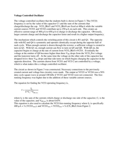
Voltage Controlled Oscillator<br />
The voltage controlled oscillator that the students built is shown in Figure 3. The (VCO)<br />
frequency is set by the value of the cap<strong>ac</strong>itor C1 and the sum of the currents that<br />
charge/discharge the cap. VCO_IRef1 and VCO_IRef4 are fixed at 400µA while the variable<br />
current sources VCO1 and VCO2 contribute up to 250 µA on e<strong>ac</strong>h side. This creates an<br />
effective current range of 400 µA to 650 µA to charge or discharge the cap<strong>ac</strong>itor. Obviously,<br />
larger currents charge and discharge the cap<strong>ac</strong>itor faster and result in a higher output frequency.<br />
The mechanism which controls the switching point of this circuit is R1 and Q1. The opposite<br />
side with R2 and Q4 is symmetric and operates identically except during the opposite half of<br />
e<strong>ac</strong>h cycle. When enough current is drawn through the resistor, a sufficient voltage is created to<br />
turn on Q1. With Q1 on, enough current can flow to turn on Q5 and Q8. With Q8 on, the<br />
cap<strong>ac</strong>itor begins to charge at the rate of current from VCO_IRef1+VCO1. Eventually the<br />
voltage at the emitter of Q8 becomes higher than three V BE drops from the VCO_Pwr voltage<br />
and the transistor turns off. At the same time the voltage on the other side of the cap<strong>ac</strong>itor has<br />
dropped below three V BE drops and that side turns on which begins charging the cap<strong>ac</strong>itor in the<br />
opposite direction. The currents drawn from VCO1 and VCO 2 are controlled by a voltage,<br />
which is what makes this a voltage controlled oscillator.<br />
The circuit as shown in Figure 3 was constructed. Necessary connections to the previously<br />
created current and voltage bias circuitry were made. The output at VCO3 or VCO4 was a 50%<br />
duty cycle square wave at around 100 kHz if VCO1 and VCO2 were not connected. The freerunning<br />
frequency was higher due to the addition of these variable current sources.<br />
The equation for finding the VCO operating frequency is,<br />
f<br />
IC<br />
=<br />
4*C *V<br />
1 BE(on)<br />
where I C is the sum of the currents which charge or discharge one side of the cap<strong>ac</strong>itor, C 1 is the<br />
value of the cap<strong>ac</strong>itor, and V BE(on) is about 0.65V.<br />
This equation is also used to calculate the VCO free-running frequency where I C is specifically<br />
400 µA + ½ (VCO1 max ), and VCO1 max = VCO2 max = ½ (CS_IRef) from Figure 2.