ac 2007-1053: a capstone analog integrated circuits ... - Icee.usm.edu
ac 2007-1053: a capstone analog integrated circuits ... - Icee.usm.edu
ac 2007-1053: a capstone analog integrated circuits ... - Icee.usm.edu

Create successful ePaper yourself
Turn your PDF publications into a flip-book with our unique Google optimized e-Paper software.
The break frequency should be low compared to the VCO free-running frequency, but not too<br />
low as to block the intended modulating frequency. For instance, if the goal is trying to recover<br />
modulated audio frequencies from a high-frequency FM signal, the filter break frequency should<br />
not be below several kHz, because then it would start filtering out the audio signal. Also, the<br />
PLL may have trouble tr<strong>ac</strong>king the input frequency if it is being modulated at a much higher<br />
frequency than the filter will pass. For simple testing purposes, the break frequency was set at<br />
approximately 1 kHz.<br />
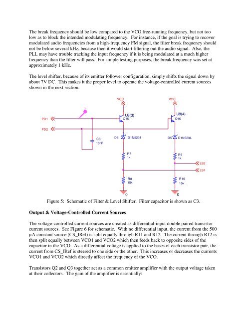
The level shifter, because of its emitter follower configuration, simply shifts the signal down by<br />
about 7V DC. This makes it the proper level to operate the voltage-controlled current sources<br />
shown in the next section.<br />
VCC<br />
VCC<br />
V<br />
PD1<br />
U8(3)<br />
Q15<br />
U8(4)<br />
Q16<br />
PD2<br />
C3<br />
10nF<br />
D6<br />
D1N5234<br />
D5<br />
D1N5234<br />
R7<br />
1k<br />
R9<br />
1k<br />
LS2<br />
LS1<br />
R8<br />
15k<br />
R10<br />
15k<br />
Figure 5: Schematic of Filter & Level Shifter. Filter cap<strong>ac</strong>itor is shown as C3.<br />
Output & Voltage-Controlled Current Sources<br />
The voltage-controlled current sources are created as differential-input double paired transistor<br />
current sources. See Figure 6 for schematic. With no differential input, the current from the 500<br />
µA constant source (CS_IRef) is split equally through R11 and R12. The current through R12 is<br />
then split equally between VCO1 and VCO2 which then feeds b<strong>ac</strong>k to opposite sides of the<br />
cap<strong>ac</strong>itor in the VCO. As a differential voltage is applied to the bases of e<strong>ac</strong>h transistor pair, the<br />
current from CS_IRef is steered to one side or the other. This increases or decreases the currents<br />
VCO1 and VCO2 which directly affect the frequency of the VCO.<br />
Transistors Q2 and Q3 together <strong>ac</strong>t as a common emitter amplifier with the output voltage taken<br />
at their collectors. The gain of the amplifier is essentially:<br />
0<br />
0