ac 2007-1053: a capstone analog integrated circuits ... - Icee.usm.edu
ac 2007-1053: a capstone analog integrated circuits ... - Icee.usm.edu
ac 2007-1053: a capstone analog integrated circuits ... - Icee.usm.edu

You also want an ePaper? Increase the reach of your titles
YUMPU automatically turns print PDFs into web optimized ePapers that Google loves.
Purpose and Objectives<br />
The concept of a phase-locked loop was first developed in the 1930s. It has since been used in<br />
communications systems of many types. A phase-locked loop is a closed-loop feedb<strong>ac</strong>k control<br />
system, and its main purpose is to maintain a generated signal in a fixed phase relationship to a<br />
reference signal. Until recently, however, phase-locked loop systems have been too costly and<br />
complex for most consumer and industrial markets where other appro<strong>ac</strong>hes were more<br />
economical. However, the PLL is particularly useful to monolithic construction, and <strong>integrated</strong>circuit<br />
phase-locked loops can now be fabricated at very low cost. Their use has become<br />
attr<strong>ac</strong>tive for many applications including FM demodulators, stereo demodulators, tone<br />
detectors, frequency synthesizers, and the like.<br />
The objective of this lab is to design and construct a phase-locked loop using only discrete<br />
components. The circuit must perform up to specific design requirements which are reasonable<br />
for PLL systems. The timeline for this project is less than 10 weeks.<br />
Materials & Equipment<br />
• CA3046 NPN Transistor array p<strong>ac</strong>kages<br />
• 6.2V Zenor Diodes<br />
• Various Resistors<br />
• Protoboard<br />
• Agilent 33220A Function Generator<br />
• Hewlett P<strong>ac</strong>kard 54600B Oscilloscope<br />
Theory of Operation<br />
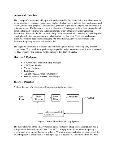
A block diagram of a phase-locked loop system is shown below.<br />
Input<br />
Signal<br />
Phase<br />
Detector<br />
Loop<br />
Filter<br />
Amplifier<br />
Output<br />
Voltage-controlled<br />
Oscillator<br />
Figure 1: Basic Phase-Locked Loop System.<br />
The basic elements of the PLL system are a phase detector, a loop filter, an amplifier, and a<br />
voltage-controlled oscillator (VCO). The VCO is simply an oscillator whose frequency is<br />
proportional to an externally applied voltage. When the loop is locked on an input signal, the<br />
VCO frequency is ex<strong>ac</strong>tly equal to the input signal’s frequency. The output of the VCO is a