ac 2007-1053: a capstone analog integrated circuits ... - Icee.usm.edu
ac 2007-1053: a capstone analog integrated circuits ... - Icee.usm.edu
ac 2007-1053: a capstone analog integrated circuits ... - Icee.usm.edu

Create successful ePaper yourself
Turn your PDF publications into a flip-book with our unique Google optimized e-Paper software.
VCO_Pwr<br />
R1<br />
3.5k<br />
Q1<br />
U5(1)<br />
VCC<br />
Q4<br />
U5(3)<br />
R2<br />
3.5k<br />
U5(4)<br />
Q5<br />
Q6<br />
U6(1)<br />
V<br />
VCO3<br />
VCO4<br />
U6(3)<br />
Q7<br />
Q8<br />
U6(4)<br />
VCO_IRef 2<br />
VCO_IRef 3<br />
C1<br />
1.52nF<br />
VCO_IRef 1<br />
VCO1<br />
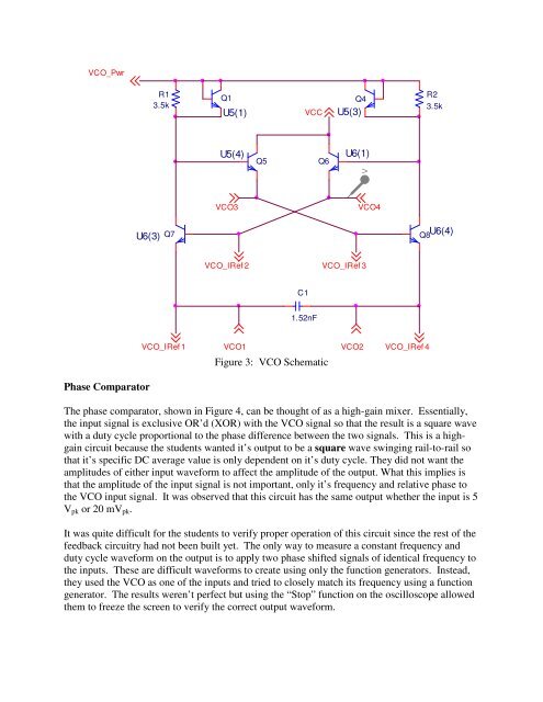
Figure 3: VCO Schematic<br />
VCO2<br />
VCO_IRef 4<br />
Phase Comparator<br />
The phase comparator, shown in Figure 4, can be thought of as a high-gain mixer. Essentially,<br />
the input signal is exclusive OR’d (XOR) with the VCO signal so that the result is a square wave<br />
with a duty cycle proportional to the phase difference between the two signals. This is a highgain<br />
circuit because the students wanted it’s output to be a square wave swinging rail-to-rail so<br />
that it’s specific DC average value is only dependent on it’s duty cycle. They did not want the<br />
amplitudes of either input waveform to affect the amplitude of the output. What this implies is<br />
that the amplitude of the input signal is not important, only it’s frequency and relative phase to<br />
the VCO input signal. It was observed that this circuit has the same output whether the input is 5<br />
V pk or 20 mV pk .<br />
It was quite difficult for the students to verify proper operation of this circuit since the rest of the<br />
feedb<strong>ac</strong>k circuitry had not been built yet. The only way to measure a constant frequency and<br />
duty cycle waveform on the output is to apply two phase shifted signals of identical frequency to<br />
the inputs. These are difficult waveforms to create using only the function generators. Instead,<br />
they used the VCO as one of the inputs and tried to closely match its frequency using a function<br />
generator. The results weren’t perfect but using the “Stop” function on the oscilloscope allowed<br />
them to freeze the screen to verify the correct output waveform.