Instruction manual - Elpro Drive, s. r. o.
Instruction manual - Elpro Drive, s. r. o.
Instruction manual - Elpro Drive, s. r. o.

You also want an ePaper? Increase the reach of your titles
YUMPU automatically turns print PDFs into web optimized ePapers that Google loves.
EL-FI DCM<br />
DRAINAGE CONTROL MONITOR<br />
MONITORS AND CONTROLS DRAINAGE PUMPS (SINGLE OR<br />
DUAL PUMP SYSTEM) WITH DRY RUNNING PROTECTION<br />
INSTRUCTION MANUAL
Patent<br />
DCM is based on technology for which patent is pending.<br />
NOTE! El-Fi DCM does not contain any user-serviceable parts. Breaking the seal over the<br />
front panel and housing will invalidate the warranty.<br />
2
Valid for the following model:<br />
El-Fi DCM<br />
Document number: 01-2120-01<br />
Edition: r1<br />
Date of release: 2000-10-13<br />
© Copyright Emotron AB 2000<br />
Emotron reserves the right to change specifications and illustrations in the text,<br />
without prior notification. The contents of this document may not be copied<br />
without the explicit permission of Emotron AB.
QUICK SET-UP<br />
All settings are in<br />
the default.<br />
Place the pump in the pit and switch the power on.<br />
Window 00<br />
indicates an<br />
alarm?<br />
YES<br />
Check the Troubleshooting<br />
procedure.<br />
NO<br />
Press the START button<br />
The pump is<br />
running.<br />
NO<br />
Press the AUTO SET<br />
key for 3 seconds<br />
(while the pump is<br />
stopped) until SEt is<br />
shown in the window.<br />
The Stop Level (window<br />
11) is set to 0.<br />
YES<br />
Set window 13 to Auto Set<br />
when the pump<br />
doesn´t snore ( )<br />
NO<br />
The pump is<br />
snoring.<br />
YES<br />
Set window 13 to Auto Set<br />
when the pump is<br />
snoring ( )<br />
Press the AUTO SET key for 3 s until<br />
SEt is shown in the window. The Stop<br />
Level (window 11) is set automatically.<br />
08-F02<br />
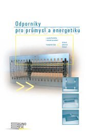
Fig. 1<br />
Quick set-up for single-pump system (the pump will start and stop during the set-up).<br />
4
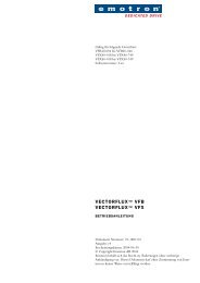
Place both pumps in the pit and<br />
switch the power on.<br />
Both pumps will start running now.<br />
Setup the MASTER DCM window<br />
71 to 2.<br />
Setup the SLAVE DCM window<br />
71 to 3.<br />
Continue from here with the<br />
Quick Setup 1-Pump on<br />
the MASTER, see Fig. 1.<br />
Press the Start key on the SLAVE.<br />
Continue from here with the<br />
Quick Setup 1-Pump on<br />
the SLAVE, see Fig. 1.<br />
Fig. 2<br />
Quick set-up for dual-pump system (the pumps will start and stop during the set-up).<br />
5
CONTENTS<br />
1. INTRODUCTION .......8<br />
1.1 Inspection and unpacking ...........8<br />
1.2 General description ....................9<br />
2. SAFETY .............. 12<br />
2.1 Dismantling and Disposal .........12<br />
3. INSTALLATION ...... 13<br />
3.1 Choice of current transformer ...13<br />
3.2 The operator´s panel ................16<br />
3.3 Description of functions ...........19<br />
3.4 Connection terminals ...............24<br />
4. SINGLE-PUMP SYSTEM<br />
INSTALLATION ...... 25<br />
4.1 Single-pump system connection.26<br />
4.2 Detailed set-up for<br />
single-pump system .................29<br />
4.3 Returning to the<br />
default settings ........................31<br />
5. DUAL-PUMP SYSTEM<br />
INSTALLATION ...... 32<br />
5.1 Dual-pump system connection . 34<br />
5.2 Detailed set-up for<br />
dual-pump system ................... 36<br />
5.3 Returning to the<br />
default settings........................ 39<br />
6. PROTECTION AND<br />
ALARM ............... 40<br />
6.1 Phase sequence (F1) .............. 40<br />
6.2 Phase asymmetry (F2) ............ 41<br />
6.3 Checking the current<br />
transformer (F3) ..................... 41<br />
6.4 Operating fault (F4) ................ 42<br />
6.5 Fault terminal 5 (F5) ............... 42<br />
6.6 Under-voltage (LU)/<br />
Overvoltage (OU) alarm ........... 43<br />
7. TROUBLESHOOTING . 44<br />
8. TECHNICAL DATA .. 46<br />
8.1 EU specifications .................... 49<br />
8.2 US specifications .................... 49<br />
6
8.3 Canada specifications ...............50<br />
8.4 Window Parameters .................51<br />
List of tables<br />
Table 1 Table for selection of current<br />
transformer for motors with a<br />
rated current up to 100 A. ......14<br />
Table 2 Table for selection of current<br />
transformers for motors with a<br />
rated current greater<br />
than 100 A. ...........................15<br />
Table 3 Symbols on the LCD display. ..17<br />
Table 4 Function of the keys. .............18<br />
Table 5 Labelling and functions of<br />
connection terminals. ............24<br />
Table 6 Alarm indications. ..................43<br />
Table 7 Technical data. ......................47<br />
Table 8 Window parameters<br />
and defaults. .........................51<br />
List of figures<br />
Fig. 1 Quick set-up for single-pump<br />
system ................................... 4<br />
Fig. 2 Quick set-up for dual-pump<br />
system ................................... 5<br />
Fig. 3 The front panel of El-Fi DCM<br />
with an El-Fi CTM current<br />
transformer. .......................... 11<br />
Fig. 4 The display ........................... 16<br />
Fig. 5 Menu structure of the<br />
El-Fi DCM single-pump ........... 20<br />
Fig. 6 Menu structure of the<br />
El-Fi DCM dual-pump ............. 21<br />
Fig. 7 Pump cycle example with<br />
different level settings<br />
in window 21. ....................... 22<br />
Fig. 8 Type of Auto Set ................... 23<br />
Fig. 9 Single-pump example. ........... 25<br />
Fig. 10 Dual- pump application. ......... 32<br />
Fig. 11 Dual-pump example. .............. 33<br />
Fig. 12 Dimensions El-Fi DCM. .......... 46<br />
7
1. INTRODUCTION<br />
EL-FI DCM is a Drainage Control Monitor from Emotron that remotely controls<br />
submersible pump equipment. The pump stops when it begins to snore (draw air)<br />
when the pit has been pumped free from water. During a pumping operation, the<br />
monitor measures the length of the run period and uses this to determine the length<br />
of the rest period. The longer the run period, the shorter the rest period. As a result<br />
the run and the rest periods are continuously adapted to the rate of flow.<br />
Two El-Fi DCM Drainage Control Monitors can be connected in parallel to control<br />
two submersible pumps and allow independent operation and display of monitored<br />
values. This instruction <strong>manual</strong> contains complete instructions for the<br />
installation and use of the monitor. Please read the entire <strong>manual</strong> before installing or<br />
using the monitor.<br />
1.1 Inspection and unpacking<br />
The delivery comprises:<br />
• EL-FI DCM Drainage Control Monitor<br />
• <strong>Instruction</strong> Manual<br />
• El-Fi current transformer<br />
8 INTRODUCTION
All products from Emotron are carefully controlled and packed. However damage<br />
may occasionally occur during transport.<br />
When you receive the package, check all items against the packing list. If anything<br />
is missing or is damaged, contact the supplier and the forwarding agent. Keep the<br />
packaging for possible inspection by the forwarding agent, or to return the delivery.<br />
1.2 General description<br />
El-Fi DCM measures the input power by measuring voltage and current. This gives a<br />
reliable measurement of pump motor load over the total load range.<br />
The monitor is connected to the pump motor supply cable with a standard El-Fi<br />
current transformer. The same monitor is suitable for small and large induction<br />
motors and the only accessory needed is a current transformer.<br />
El-Fi DCM is enclosed in a recyclable PC/ABS plastic housing. At the front is the<br />
operator´s panel which comprises a LCD-display and a set of six keys. The connection<br />
terminals are at the top and the bottom of the monitor front panel. The monitor<br />
should be mounted on a standard DIN-rail.<br />
El-Fi DCM is very easy to use. The AUTO SET function makes it possible to<br />
adjust the monitor automatically by pressing just one key individually for each pump.<br />
El-Fi DCM always stops the pump at when it starts to snore and restarts it after a calculated<br />
pause time or in response to a high-level switch-over.<br />
INTRODUCTION 9
El-Fi DCM is able to check;<br />
• Phase sequence.<br />
• Phase asymmetry.<br />
• Current transformer (Primary windings).<br />
• Temperature monitoring on pump motor.<br />
• Under-voltage and Overvoltage.<br />
El-Fi DCM gives information about;<br />
• Delay before restarting after the pump has stopped.<br />
• Pumping time since the latest pump start.<br />
• High-level pumping time since the pump started as a resault of high-level switch.<br />
• Measured power as percentage of the monitor´s measurement range.<br />
• Measured voltage.<br />
• Measured peak power as percentage of the monitors measurement range.<br />
• Time counter for total pumping time.<br />
• Start counter - total number of times pump has started.<br />
El-Fi DCM can be connected in parallel for dual-pump system.<br />
• Adjustment<br />
• MASTER/SLAVE function<br />
• If there is a breakdown in one of the pumps the other pump starts to operate.<br />
10 INTRODUCTION
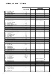
emotron<br />
Fig. 3<br />
The front panel of El-Fi DCM with an El-Fi CTM current transformer.<br />
INTRODUCTION 11
2. SAFETY<br />
• Read the “Technical Data” chapter of this <strong>manual</strong> thoroughly before installing<br />
and using the monitor.<br />
• The monitor should be installed only by a qualified technician.<br />
• Always disconnect supply circuits prior to installing, connecting or disconnecting<br />
the monitor.<br />
• The installation must comply with general and local regulations.<br />
2.1 Dismantling and Disposal<br />
The housing of the El-Fi DCM is made of recyclable PC/ABS plastic, and the circuit<br />
boards contain small amounts of tin and lead. When disposed of, all parts must be<br />
handled and recycled in accordance with local regulations.<br />
12 SAFETY
3. INSTALLATION<br />
El-Fi DCM must be installed and commissioned only by an authorized person<br />
according to the local safety regulations.<br />
The monitor is mounted on a standard DIN-rail 46277, 35 mm. See “Technical<br />
Data” for maximum operating temperature range, monitor dimensions etc. Before<br />
installing, make sure that no voltage is applied to the equipment and that the voltage<br />
rating of the monitor, as shown on the rating plate on the side of the monitor, corresponds<br />
to the line voltage.<br />
3.1 Choice of current transformer<br />
Depending on the motor size, El-Fi DCM should be used with one or two current<br />
transformers. For pump motors with a rated current up to 100 A, use a single El-Fi<br />
current transformer. The possible combinations of current transformers and number<br />
of primary windings are listed in Table 1, page 14 and Table 2, page 15.<br />
INSTALLATION 13
Table 1<br />
Table for selection of current transformer for motors with a rated current up to 100 A<br />
Rated motor<br />
current<br />
Choice of current transformer and number of primary<br />
windings for different pump motor size.<br />
CTM010 CTM025 CTM050 CTM0100<br />
0.40 to 1.00 A 10<br />
1.01 to 2.00 A 5<br />
2.01 to 3.0 A 3<br />
3.1 to 5.0 A 2<br />
5.1 to 10 A 1<br />
10.1 to 12.5 A 2 4<br />
12.6 to 25 A 1 2<br />
26 to 50 A 1<br />
51 to 100 A 1<br />
For larger motors (rated current > 100 A), use two current transformers - one outer,<br />
standard transformer and one El-Fi CTM010 with two primary windings. Table 2,<br />
page 15 shows the choice of transformers and number of windings for currents<br />
exceeding 100 A.<br />
14 INSTALLATION
Table 2 Table for selection of current transformers for motors with a rated current greater than 100 A.<br />
Rated motor current<br />
Current transformers<br />
Number of primary windings<br />
150:5 + CTM010<br />
101 to 150 A<br />
1 + 2<br />
250:5 + CTM010<br />
151 to 250 A<br />
1 + 2<br />
500:5 + CTM010<br />
251 to 500 A<br />
1 + 2<br />
1000:5 + CTM010<br />
501 to 999 A<br />
1 + 2<br />
The following examples illustrate the choice of current transformer(s):<br />
• Example A. Pump motor has a rated current of 6.9 A. According to Table 1, page<br />
14, choose El-Fi CTM010 with one (1) primary winding.<br />
• Example B. Pump motor has a rated current of 108 A. Choose a standard current<br />
transformer 150:5 with one (1) primary winding and an El-Fi CTM010 with two<br />
(2) primary windings.<br />
NOTE! The current transformer(s) must be used according to Table 1, page 14 and Table 2,<br />
page 15. Make sure to wind the transformer(s) with the correct number of windings.<br />
INSTALLATION 15
3.2 The operator´s panel<br />
The operator’s panel comprises a LCD-display and a set of six keys (Fig. 3, page 11)<br />
on the front panel of the El-Fi DCM. The display provides five digits and eight symbols,<br />
see Fig. 4, page 16. The symbols are explained in Table 3, page 17.<br />
The two smaller digits on the left of the display show the window number. Each<br />
window (e.g. 00, 01, 02) contains a parameter (e.g. 125, 0.99, on, OFF) whose value<br />
is shown by the three larger digits or characters to the right. When the value is<br />
greater than 999 all five digits are used to display the parameter value, alternating<br />
with the window number. For example, the window number 21 is displayed for 2<br />
seconds and then the value 12345 is displayed for 2 seconds. The functions of the keys<br />
are explained in Table 4, page 18.<br />
Fig. 4<br />
The display<br />
16 INSTALLATION
Table 3<br />
Symbols on the LCD display.<br />
Symbol<br />
Meaning<br />
Flashing when alarm triggered.<br />
Indicates when the value is time.<br />
Parameter settings are locked.<br />
V Volts<br />
mA Milliamperes<br />
m Minutes<br />
S Seconds<br />
% Percent<br />
INSTALLATION 17
Table 4<br />
Function of the keys.<br />
Key<br />
Function<br />
RESET/START Resets a latched alarm/Starts the pump motor.<br />
AUTO SET The stop level is automatically set when the button is held for 3s.<br />
NEXT Proceed to the next window.<br />
- Decrease the displayed value.<br />
+ Increase the displayed value.<br />
ENTER Confirm the adjustments made.<br />
18 INSTALLATION
3.3 Description of functions<br />
The windows are represented in a menu structure of only one level, as shown in Fig.<br />
5, page 20 (single-pump version) and Fig. 6, page 21 (dual-pump version). The windows,<br />
their functions, and possible values are presented in Table 8, page 51.<br />
When delivered, El-Fi DCM is pre-programmed with the default settings shown<br />
in Table 8, page 51.<br />
One minute after any of the front panel keys is pressed, the El-Fi DCM returns to:<br />
• window 00 if an alarm has been triggered<br />
• window 01 if the pump is pausing. When DCM is SLAVE it displays _ _ _ .<br />
• window 02 if the pump is pumping. When DCM is MASTER and the DCM<br />
SLAVE is pumping it displays _ _ _ .<br />
• window 03 if the pump is pumping and it started as a result of a high-level<br />
switch-over.<br />
INSTALLATION 19
00<br />
01<br />
02<br />
03<br />
99<br />
04<br />
05<br />
71<br />
06<br />
07<br />
08<br />
61<br />
09<br />
53<br />
11<br />
52<br />
51<br />
42<br />
21<br />
13<br />
12<br />
41<br />
22<br />
32<br />
23<br />
31<br />
24<br />
08-F03<br />
Fig. 5 Menu structure of the El-Fi DCM single-pump (see also Table 8, page 51).<br />
20 INSTALLATION
00<br />
01<br />
02<br />
03<br />
04<br />
71<br />
99<br />
72<br />
73<br />
05<br />
06<br />
07<br />
08<br />
09<br />
61<br />
53<br />
11<br />
52<br />
51<br />
42<br />
21<br />
13<br />
12<br />
41<br />
22<br />
32<br />
23<br />
31<br />
24<br />
(08-F09)<br />
Fig. 6 Menu structure of the El-Fi DCM dual-pump (see also Table 8, page 51).<br />
INSTALLATION 21
Example 1<br />
Example 2<br />
Volume in the pit in litre<br />
700<br />
600<br />
500<br />
400<br />
300<br />
200<br />
Inflow 300 litre/min<br />
Pump Capacity 600 litre/min<br />
Window 21 is set to 1<br />
Volume in the pit in litre<br />
700<br />
600<br />
500<br />
400<br />
300<br />
200<br />
Inflow 100 litre/min<br />
Pump Capacity 600 litre/min<br />
Window 21 is set to 1<br />
100<br />
100<br />
Volume in the pit in litre<br />
0<br />
1600<br />
1400<br />
1200<br />
1000<br />
800<br />
600<br />
400<br />
Example 3<br />
Inflow 300 litre/min<br />
Pump Capacity 600 litre/min<br />
Window 21 is set to 2,3<br />
Time<br />
(08-F06)<br />
0<br />
Time<br />
(08-F07)<br />
Volume in the pit at pump start after<br />
pause time=is equal to Pump Capacity<br />
(litre/min) multiplied by Level Setting<br />
(window 21)<br />
Example 1 and 2: Pump capacity<br />
600 (litre/min) x 1 (Value in window 21)<br />
= 600 litre in the pit when pump start to<br />
pump.<br />
200<br />
0<br />
Time<br />
(08-F08)<br />
Example 3: Pump Capacity 600 (litre/<br />
min) x 2.3 (Value in window 21) = 1380<br />
litre in the pit when pump start to pump.<br />
Fig. 7 Pump cycle example with different level settings in window 21.<br />
22 INSTALLATION
Power<br />
A1<br />
A2<br />
B2<br />
B1<br />
A3<br />
B3<br />
Time<br />
When there is liquid in the pit<br />
A1=Motorload when the pump doesn´t snore (Window 13 is set to ( - ))<br />
A2=Stop level if AUTO SET is pressed when the pump doesn´t snore<br />
A3=Snore margin<br />
When there is NO liquid in the pit<br />
B1=Motorload when the pump is snoring/dry pumping (Window 13 is set to (_))<br />
B2=Stop level if AUTO SET is pressed when the pump is snoring/dry pumping<br />
B3=Snore margin<br />
Fig. 8<br />
Type of Auto Set<br />
(08-F11)<br />
INSTALLATION 23
3.4 Connection terminals<br />
There are 13 labelled connection terminals on the front panel of the El-Fi DCM.<br />
Table 5<br />
Labelling and functions of connection terminals.<br />
Terminal Label Function<br />
1 S1 Current transformer input.<br />
2 S2 Current transformer input.<br />
3 DIG<br />
Digital input for closing contact. High-level switch or external<br />
Reset/Auto Set. In dual-pump applications the terminal 3 is also<br />
used for communication between the two DCM.<br />
4 SGND Signal ground.<br />
5 TEMP<br />
Input for motor thermistor PTC, thermocontact or motor<br />
protection relay.<br />
6 ALARM<br />
7 C Relay common.<br />
8 PUMP<br />
9 L1 Motor voltage.<br />
10 (not used)<br />
11 L2 Motor voltage.<br />
12 (not used)<br />
13 L3 Motor voltage.<br />
Alarm relay. (On the DCM MASTER use this terminal in series with<br />
the high-level switch.<br />
Operation of relay pump motor (control signals for start and stop<br />
equipment).<br />
24 INSTALLATION
4. SINGLE-PUMP SYSTEM INSTALLATION<br />
L1<br />
L2<br />
L3<br />
N<br />
PE<br />
Exceeding 100 Amp<br />
Number of primary windings see table 2<br />
EL-FI L1<br />
CTM010<br />
Standard<br />
transformer<br />
Autoset<br />
2 turns<br />
Max 240VAC<br />
Reset<br />
Alarm<br />
Up to 100 Amp<br />
Number of primary windings see table 1<br />
High level<br />
Stop<br />
K1<br />
L1<br />
EL-FI CTM<br />
1 2 3 4 5 6 7 8<br />
S1 S2 Dig SGND Temp AlarmC Pump<br />
RESET<br />
START<br />
L1L2L3<br />
91113<br />
Alternative connection<br />
Thermistor PTC<br />
+<br />
-<br />
UVWPE<br />
M<br />
3~<br />
Thermocontact<br />
08-F01<br />
Fig. 9<br />
Single-pump example.<br />
SINGLE-PUMP SYSTEM INSTALLATION 25
4.1 Single-pump system connection<br />
4.1.1 Supply voltage connection (L1, L2 & L3)<br />
Connect El-Fi DCM (3-phase installation) directly to the pump motor supply cable<br />
via terminals 9 (L1), 11 (L2), and 13 (L3). Make the connection before the contactor<br />
of the motor, to ensure that the monitor also receives power when the motor is not<br />
in use. When motor fuses larger than 10 A are used, the monitor (power consumption<br />
6 VA) must be fused independently, see Fig. 9, page 25.<br />
4.1.2 Current transformer connection (S1 & S2)<br />
Connect the current transformer to terminal 1 (S1) and terminal 2 (S2). The transformer<br />
MUST be linked to the phase connected to terminal 9 (L1), see Fig. 9, page<br />
25.<br />
When two current transformers are used (for motors with a rated current greater<br />
than 100 A), always connect the El-Fi CTM010 to the monitor and one outer standard<br />
current transformer with 2 primary windings through the El-FI CTM010, see<br />
Fig. 9, page 25.<br />
NOTE! Before connecting the current transformer(s), study chapter 3.1, page 13 carefully<br />
to determine the correct number of windings.<br />
26 SINGLE-PUMP SYSTEM INSTALLATION
4.1.3 Alarm relay connection (ALARM & C)<br />
Terminals 6 and 7 are the alarm relay connections. Terminal 6 (ALARM) is the alarm<br />
relay output. Terminal 7 (C) is the common input for the alarm relay, see Fig. 9, page<br />
25.<br />
When powered off, the alarm relay is nc (normally closed). When powered on,<br />
nc or no (normally open) can be selected, see Table 8, on page 51, window 51.<br />
4.1.4 Operation relay connection (PUMP & C)<br />
Terminals 7 and 8 are the operating relay connections that control the start and stop<br />
equipment for the pump motor.<br />
Terminal 8 (PUMP) is an operating relay output. Terminal 7 (C) is the common<br />
input for the operation relay, see Fig. 9, page 25.<br />
When powered off, the operating relay is no. When powered on, nc or no can<br />
be selected (nc means that the relay contact is closed when the pump is running), see<br />
Table 8, on page 51 window 52.<br />
4.1.5 Digital input connection (DIG & SGND)<br />
Terminals 3 (DIG) and 4 (SGND) are connections for a closing contact between<br />
DIG and SGND. The terminals are galvanically isolated. Pull-up resistor to internal<br />
supply (15-30V). The impedance is more than 1kohm.<br />
SINGLE-PUMP SYSTEM INSTALLATION 27
The three functions that can be initiated by the digital input are:<br />
1. High-Level Switch.<br />
2. External reset.<br />
3. External Auto Set.<br />
See Fig. 9, page 25 and Table 8, on page 51, Window 53.<br />
4.1.6 Temperature measuring input connection (TEMP & SGND)<br />
Terminals 4 and 5 are the temperature measuring input and/or motor protection<br />
contact connections. The motor protection relay can be connected in series with the<br />
temperature sensor. The terminals are galvanically isolated. Terminal 5 (TEMP) is for<br />
a PTC-type thermistor or thermocontact. The sensor must have a resistance of less<br />
than 800ohm under normal operation and more than 3kohm at high temperature.<br />
Internal supply 12 V. Short-circuit current 2 to 2.5 mA. Terminal 4 (SGND) is the<br />
signal ground for the temperature measuring input. See Fig. 9, page 25 and Table 8,<br />
page 51, Windows 31 and 32.<br />
28 SINGLE-PUMP SYSTEM INSTALLATION
4.2 Detailed set-up for single-pump system<br />
WARNING! The pump starts and stops during set-up.<br />
NOTE! Disconnect the wire on terminal 18 to prevent involuntary starting and stopping of<br />
the pump during set-up steps 1 to 13.<br />
Setting up of the El-Fi DCM<br />
The steps below illustrate examples of how to program the monitor. When the<br />
power is turned on, press NEXT to proceed to the next window, press + or - to<br />
increase or decrease the value and press ENTER to confirm the new value in each<br />
window. For quick set-up, see Fig. 1, page 4.<br />
1. Place the pump in the pit and switch the power on.<br />
2. Check window 71 if the value is 1 (single-pump system).<br />
3. In window 13 select type of Auto Set. Set the window to ( - ) if the pump is<br />
pumping without snoring (there is liquid in the pit). Set the window to (_) if the<br />
pump is snoring (no liquid in the pit) set, see Fig. 8, page 23.<br />
4. In window 22 set the maximum pause time between 0-720 minutes.<br />
5. In window 23 set the required start-up delay between 1-170 s. Start-up delay<br />
time is the time between the pump starting and the time when snoring is<br />
detected.<br />
SINGLE-PUMP SYSTEM INSTALLATION 29
6. In window 24 set the required Stop delay between 1-90 seconds. The stop delay<br />
is the time between the pump starting to snore and the time when the pump<br />
motor stops.<br />
7. In window 31, if the pump has a temperature sensor and/or motor protection, set<br />
the temperature monitoring to (on). If not, set the window to (OFF). See chapter<br />
6.5, page 42 and Fig. 9, page 25.<br />
8. In window 32 if window 31 is set to (on). Choose temperature alarm latched (on)<br />
or temperature alarm not latched (OFF). See chapter 6.5, page 42.<br />
9. In window 41 the permitted phase asymmetry is set between 5% and 50%. Phase<br />
asymmetry monitoring is turned off by pressing -, when the window shows 5%.<br />
To turn the monitoring on again press + and select a value, chapter 6.2, page 41.<br />
10.In window 42, if the window 41 value is between 5% and 50%, choose phase<br />
asymmetry alarm latched (on) or phase asymmetry alarm not latched (OFF). See<br />
chapter 6.2, page 41.<br />
11.In window 51 set the alarm relay contact function to no (normally open) or nc<br />
(normally closed), see chapter 4.1.3, page 27.<br />
12.In window 52 set the operating relay contact function, see chapter 4.1.4, page 27.<br />
13.In window 53 set the required function for the digital input (DIG), Value: (1)<br />
high-level switch, (2) external reset, (3) external Auto Set, chapter 4.1.5, page 27.<br />
14.Connect the start and stop equipment to terminal 8.<br />
30 SINGLE-PUMP SYSTEM INSTALLATION
15.Check that the pump is pumping in accordance to the setting in window 13 (set<br />
the stop level in window 11 to 0 (default) if the pump stops before or during the<br />
Auto Set). Press the AUTO SET button and hold for 3 seconds until SEt appears<br />
in the window. The stop level (window 11) becomes measured power (window<br />
04) minus snore margin (window 12) if window 13 is set to ( - ). The stop level<br />
(window 11) becomes measured power (window 04) plus snore margin (window<br />
12) if window 13 is set to (_), see Fig. 8, page 23.<br />
16.Change the level setting in window 21 between 1-10 for shorter or longer pump<br />
cycles and levels in the pit. A low value gives shorter pump cycles and lower level<br />
in the pit. See Fig. 7, page 22.<br />
17.It is possible to avoid unintentional changes of set parameters. Set window 09 to<br />
369 and confirm with ENTER. A padlock is shown in the window. If the value<br />
369 is re-entered in window 09, confirmed by ENTER the settings are unlocked.<br />
4.3 Returning to the default settings<br />
1. To return to the default settings go to window 99.<br />
2. If any value differs from the default values (see Table 8, page 51), “Usr” (set by the<br />
user) is displayed in the window.<br />
3. Press + to return to the default settings. “dEF” (default setting) is shown in the<br />
window. Confirm by pressing ENTER.<br />
NOTE! Windows 6, 7 and 8 are set to 0.<br />
SINGLE-PUMP SYSTEM INSTALLATION 31
CTM<br />
CTM<br />
5. DUAL-PUMP SYSTEM INSTALLATION<br />
P1<br />
0 0<br />
P2<br />
K1<br />
K2<br />
12345678<br />
12345678<br />
High level switch<br />
Reset<br />
Start<br />
Auto<br />
Set<br />
Next<br />
Reset<br />
Start<br />
Auto<br />
Set<br />
Next<br />
Enter<br />
Enter<br />
9 11 13<br />
9 11 13<br />
K1<br />
K2<br />
P1<br />
P2<br />
Fig. 10 Dual- pump application.<br />
32 DUAL-PUMP SYSTEM INSTALLATION
L1<br />
L2<br />
L3<br />
N<br />
PE<br />
Max 240VAC<br />
Max 240VAC<br />
K1<br />
Stop<br />
K2<br />
Stop<br />
U V W<br />
U V W<br />
M<br />
M<br />
3~ 3~<br />
Max 240VAC<br />
Alarm<br />
High<br />
Level<br />
Switch<br />
or<br />
External<br />
1 2 3 4 5 6 7 8 1 2 3 4 5 6 7 8<br />
S1 S2Dig<br />
SGNDTemp<br />
Alarm C Pump Reset<br />
S1 S2Dig<br />
SGND Temp Alarm CPump<br />
DCM<br />
MASTER<br />
DCM<br />
SLAVE<br />
L1 L2 L3<br />
L1 L2 L3<br />
9 11 13 9 11 13<br />
Fig. 11 Dual-pump example.<br />
DUAL-PUMP SYSTEM INSTALLATION 33
5.1 Dual-pump system connection<br />
(Parallel connection of 2 EL-FI DCM)<br />
5.1.1 Dual-pumps supply connection (L1, L2 & L3)<br />
Connect the main voltage from each pump to the respective EL-FI DCM as<br />
described in chapter 4.1.1, page 26. See Fig. 11, page 33.<br />
5.1.2 Dual-pumps current transformer connection (S1 & S2)<br />
Connect the current transformers from each pump to the respective EL-FI DCM as<br />
described in chapter 4.1.2, page 26. See Fig. 11, page 33.<br />
5.1.3 Dual-pumps alarm relay connection (ALARM &C)<br />
Terminal 6 and 7 on the DCM SLAVE are the alarm relay connections. These terminals<br />
indicates an alarm if a fault is detected by DCM MASTER or DCM SLAVE.<br />
See Fig. 11, page 33. When powered off the alarm relay is nc (normally closed).<br />
When powered on, nc or no (normally open) can be selected. See Table 8, on page<br />
51, window 51.<br />
34 DUAL-PUMP SYSTEM INSTALLATION
5.1.4 Dual-pumps communication and digital input connection (DIG &<br />
SGND)<br />
Terminals 3 (DIG) and 4 (SGND) are connections for closing contacts and for communicating<br />
between DCM MASTER and DCM SLAVE. The digital Input can be<br />
used for high-level switch or external reset. The high-level switch must be connected<br />
in serial with DCM MASTER terminal 6 (ALARM) and terminal 7 (C). When<br />
external reset is chosen use pulse signal. Connect terminal 3 (DIG) on the DCM<br />
MASTER to terminal 3 (DIG) on the DCM SLAVE. Connect terminal 4 (SGND)<br />
on the DCM MASTER to terminal 4 (SGND) on the DCM SLAVE. See Fig. 11,<br />
page 33 and Table 8, on page 51, window 53.<br />
5.1.5 Dual-pump operation relay connection (PUMP)<br />
Connect the control signals for the start and stop equipment for each pump to the<br />
respective EL-FI DCM as described in chapter 4.1.4, page 27, see Fig. 11, page 33.<br />
5.1.6 Dual-pumps temperature measuring input connection (TEMP &<br />
SGND)<br />
Connect temperature sensor and/or motor protection for each pump to the respective<br />
EL-FI DCM as described in chapter 4.1.6, page 28. See Fig. 11, page 33.<br />
DUAL-PUMP SYSTEM INSTALLATION 35
5.2 Detailed set-up for dual-pump system<br />
(always use two El-Fi DCMs)<br />
WARNING! The pumps start and stop during the set-up.<br />
NOTE! Disconnect the wire on terminal 8 on both DCMs to prevent starting and stopping<br />
the pump unintentionally during set-up, steps 1-14.<br />
Setting up of the El-Fi DCM<br />
The steps below illustrate examples of how to program the monitor. When the<br />
power is turned on, press NEXT to proceed to the next window, press + or - to<br />
increase or decrease the value and press ENTER to confirm the new value in each<br />
window. For quick set-up, see Fig. 2, page 5.<br />
1. In window 71 set the required monitor function. Dual-pump control MASTER<br />
(2) for one of the EL-FI DCMs and for the other EL-FI DCM dual-pump control<br />
SLAVE (3). The DCM MASTER must be the DCM that is wired for MAS-<br />
TER, see Fig. 11, page 33.<br />
36 DUAL-PUMP SYSTEM INSTALLATION
2. In window 72 on the MASTER DCM, set the condition for alternating the<br />
pumps. Alternate by each pump cycle (on). The SLAVE DCM starts only when<br />
the DCM MASTER shows fault codes (OFF).<br />
3. In window 73 on the MASTER DCM, set the condition for pump start-up on<br />
high-level switch. Both pumps start (on). One pump starts (OFF).<br />
4. In window 13 select type of Auto Set. Set the window to ( - ) if the pump is<br />
pumping without snoring (there is liquid in the pit). Set the window to (_) if the<br />
pump is snoring (no liquid in the pit), see Fig. 8, page 23.<br />
5. In window 22 on the MASTER DCM, set the maximum pause time between<br />
0 - 720 minutes.<br />
6. In window 23 on both DCMs, set the required start-up delay between 1-170 seconds.<br />
Start-up delay time is the time between the pump starting and the time<br />
when snoring is detected.<br />
7. In window 24 on both DCMs, set the required stop delay between 1-90 seconds.<br />
Stop delay time is the time between the pump starting to snore and the time<br />
when the pump motor stops.<br />
8. In window 31 on both DCMs. If the pump has temperature sensor and/or motor<br />
protection set temperature monitoring to (on). If not set the window to (OFF).<br />
See chapter 6.5, page 42.<br />
9. In window 32 on both DCMs if window 31 is set to on. Temperature alarm<br />
latched (on). Temperature alarm not latched (OFF). See chapter 6.5, page 42.<br />
DUAL-PUMP SYSTEM INSTALLATION 37
10.In window 41 on both DCMs, set the permitted phase asymmetry to between 5%<br />
and 50%. Phase asymmetry is turned off by pressing -, when the window shows<br />
then show 5%. To turn the monitoring on again, press + and select a value. See<br />
chapter 6.2, page 41.<br />
11.In window 42 on both DCMs if window 41 value is between 5 and 50% choose<br />
phase asymmetry alarm latched (on) or phase asymmetry alarm not latched (OFF)<br />
See chapter 6.2, page 41.<br />
12.In window 51 on the SLAVE DCM. Set the alarm relay contact function to no<br />
(normally open) or nc (normally closed), see chapter 5.1.3, page 34.<br />
13.In window 52 on both DCMs. Set the operating relay contact function. See<br />
chapter 5.1.5, page 35.<br />
14.In window 53 on both DCMs. Set the required function for the digital input<br />
(DIG), value (1) high-level switch, (2) external reset, see chapter 5.1.4, page 35.<br />
15.Connect the start and stop equipment to terminal 8.<br />
16.Check that one of the pumps is running according to the setting in window 13<br />
and that the other pump is not running (set the stop level in window 11 to 0<br />
(default) if the pump stops before or during the Auto Set). Press the AUTO SET<br />
button for 3 seconds until SEt is shown in the window. Press the START button<br />
on the other DCM. Wait until the start delay has elapsed. Press the AUTO SET<br />
button for 3 seconds until SEt is shown in the window. The stop level becomes<br />
measured power (window 04) minus snore margin (window 12) if window 13 is<br />
38 DUAL-PUMP SYSTEM INSTALLATION
set to ( - ). The stop level becomes measured power (window 04) plus snore margin<br />
(window 12) if window 13 is set to (_). See Fig. 8, page 23.<br />
17.Change the level setting in window 21 on the MASTER DCM between 1 - 10<br />
for shorter or longer pump cycles and level in the pit. A low value gives shorter<br />
pump cycles and lower level in the pit, see Fig. 7, page 22.<br />
18.It is possible to avoid unintentional changes of set parameters. Set window 09 to<br />
369 in each DCM and confirm with ENTER. A padlock is shown in the window.<br />
If the value 369 is re-entered in window 09 and confirmed by ENTER the<br />
settings are unlocked.<br />
5.3 Returning to the default settings<br />
1. To return to the default settings go to window 99.<br />
2. If any value differs from the default values (see Table 8, page 51), “Usr” (set by the<br />
user) is displayed in the window.<br />
3. Press + to return to the default settings. “dEF” (default setting) is shown in the<br />
window. Confirm by pressing ENTER.<br />
NOTE! Window 6, 7 and 8 are set to 0.<br />
DUAL-PUMP SYSTEM INSTALLATION 39
6. PROTECTION AND ALARM<br />
When an error occurs, the triangular alarm sign starts to flash and the alarm relay is<br />
activated.<br />
Window 00 becomes active and gives the information about the alarm according<br />
to the alarm list, see Table 6, page 43.<br />
Alarm in a dual-pump application<br />
The fault code is shown in window 00 of the respective DCM, the alarm relay is<br />
only set on terminal 6 of the DCM SLAVE when an error occurs. If a latched alarm<br />
occurs it must be reset on the respective DCM by pressing the RESET button or - if<br />
specified as digital input - by an external reset.<br />
6.1 Phase sequence (F1)<br />
When El-Fi DCM is first switched on, phases L1, L2 and L3 are checked for correct<br />
phase sequence.<br />
If the wrong phase sequence is detected, an F1 alarm is generated and the<br />
ALARM relay on terminal 6 is activated. The pump will not start. Switch the power<br />
off and shift phase L2 and L3.<br />
NOTE! Do not change L1.<br />
40 PROTECTION AND ALARM
6.2 Phase asymmetry (F2)<br />
The permitted phase asymmetry is set in window 41, see Table 8, page 51. Any failure<br />
shorter than 5 seconds is ignored. When phase asymmetry is detected an F2<br />
alarm is generated and the ALARM relay on terminal 6 is activated. The pump will<br />
be stopped.<br />
If window 42 is set to on the alarm can be reset by pressing the RESET button or<br />
by using the external reset signal.<br />
6.3 Checking the current transformer (F3)<br />
When AUTO SET is pressed the El-Fi DCM checks that the current transformer has<br />
the correct number of primary windings for the rated motor current, see Table 1,<br />
page 14 or Table 2, page 15.<br />
The measured current at terminals S1 and S2 is displayed in window 61. If the<br />
measured current is below 10 mA or above 60 mA, an F3 alarm is generated and the<br />
alarm relay is activated. The pump will be stopped.<br />
PROTECTION AND ALARM 41
6.4 Operating fault (F4)<br />
If the pump is snoring and the high-level switch gives the signal to pump, this is a<br />
fault situation and an F4 alarm is generated and the ALARM relay is activated. If<br />
communication between the DCM MASTER and the DCM SLAVE is interrupted<br />
an F4 alarm is generated and the ALARM relay is activated. See Fig. 11, page 33,<br />
chapter 5.1.4, page 35.<br />
6.5 Fault terminal 5 (F5)<br />
Temperature monitoring on pump motor.<br />
El-Fi DCM can use either an input thermistor (PTC) signal or thermocontact. To<br />
activate temperature monitoring, set window 31 to on.<br />
When the pump motor gets hot, the excess temperature generates an F5 alarm<br />
and activates the ALARM relay and the pump will be stopped.<br />
It is also possible to connect a motor protection relay to generate an F5 alarm. See<br />
Fig. 9, page 25 and Fig. 11, page 33.<br />
If window 32 is set to on, the alarm can be reset by pressing the RESET button<br />
or by using the external reset signal.<br />
42 PROTECTION AND ALARM
6.6 Under-voltage (LU)/Overvoltage (OU) alarm<br />
When El-Fi DCM is first switched on, the voltages on phases L1, L2 and L3 are<br />
checked.<br />
If a wrong phase voltage is detected, an LU (under-voltage) or OU (overvoltage)<br />
alarm is generated and the ALARM relay is activated. The pump will not start.<br />
Switch the power off. Check that the line voltage corresponds to the voltage range of<br />
the DCM according to the rating plate on the side of the monitor.<br />
Table 6<br />
Alarm indications.<br />
Indication Function Remark<br />
F1 Phase sequence chapter 6.1, page 40<br />
F2 Phase asymmetry chapter 6.2, page 41<br />
F3 Current transformer chapter 6.3, page 41<br />
F4 Operation fault chapter 6.4, page 42<br />
F5 Fault terminal 5 chapter 6.5, page 42<br />
LU Under-voltage chapter 6.6, page 43<br />
OU Overvoltage chapter 6.6, page 43<br />
oor Out of range chapter 7., page 44<br />
PROTECTION AND ALARM 43
7. TROUBLESHOOTING<br />
• Window 00 shows F1 Phase sequence alarm, see chapter 6.1, page 40.<br />
• Window 00 shows F2 Phase asymmetry alarm, see chapter 6.2, page 41.<br />
• Window 00 shows F3 Current transformer alarm, see chapter 6.3, page 41<br />
• Window 00 shows F4 Operation fault, see chapter 6.4, page 42.<br />
• Window 00 shows F5 Fault terminal 5, see chapter 6.5, page 42.<br />
• Window 00 shows LU Under-voltage or OU Overvoltage alarm, see chapter 6.6,<br />
page 43.<br />
Check that the line voltage corresponds to the voltage range of the monitor<br />
according to the rating plate on the side of the monitor.<br />
WARNING! Switch off the main supply!<br />
• If oor (out of range) is shown in the window it means that the value is too big.<br />
• Impossible to do Auto Set. It is impossible to do Auto Set during the start-up<br />
delay period, if an alarm indication is present or both pumps are running.<br />
• The pump starts and stops too often or the level in the pit is too low or high.<br />
Change the setting in window 21, level setting, see Fig. 7, page 22 or change the<br />
maximum pause time (window 22).<br />
44 TROUBLESHOOTING
• The pump stops although it is pumping without snoring. Check the Stop level<br />
value in window 11. This value is probably too high in relation to measured<br />
power in window 04, see Fig. 1, page 4 for single-pump system or Fig. 2, page 5<br />
for dual-pump system.<br />
• The pump doesn’t stop when snoring. Check the Stop level value in window 11.<br />
This value is probably too low in relation to measured power in window 04, see<br />
Fig. 1, page 4 for single-pump system or Fig. 2, page 5 for dual-pump system.<br />
• The value in window 04 increases when the pump starts to snore. Check that the<br />
current transformer(s) is/are linked to the phase connected to terminal 9 (L1), see<br />
chapter 4.1.2, page 26 and Fig. 9, page 25 or chapter 5.1.2, page 34.<br />
TROUBLESHOOTING 45
8. TECHNICAL DATA<br />
26 mm<br />
(1.02 ’‘ )<br />
35 mm<br />
(1.38 ’‘ )<br />
90 mm (3.54 ’‘ )<br />
45 mm (1.77’‘)<br />
115 mm (4.53’‘)<br />
Fig. 12 Dimensions El-Fi DCM.<br />
46 TECHNICAL DATA
Table 7<br />
Technical data.<br />
Dimension (WxHxD) 45 x 90 x 115 mm (1.77" x 3.54" x 4.53")<br />
Weight<br />
0.3 kg (10.5 oz)<br />
Supply voltage (VAC) 3 x 100 to 240, 3 x 380 to 500,<br />
3 x 525 to 600, 3 x 600 to 690* (±10%)<br />
Frequency<br />
45 to 65 Hz<br />
Current input<br />
El-Fi current transformer CTM010, 025, 050 or 100. (If<br />
rated current >100 A CTM010 and a standard transformer)<br />
Power consumption<br />
Max 6 VA<br />
Start-up delay<br />
1 to 170 s<br />
Stop delay<br />
1 to 90 s<br />
Digital input terminal 3 For closing contact Internal supply 15-30VDC, short-circuit<br />
current 10-20mA<br />
Temperature input terminal 5 Internal supply 15-30VDC, short-circuit current 2mA-<br />
2.5mA<br />
Relay output<br />
5 A 240 VAC Resistive. 1.5 A 240 VAC Pilot duty/AC12<br />
* only CE marked.<br />
TECHNICAL DATA 47
Table 7<br />
Technical data. (continued)<br />
Fuse<br />
Terminal wire size<br />
Max. 10 A<br />
The terminal tightening torque 5-7 Ib-in (0.56 - 0.79Nm)<br />
Repeatability<br />
Power measurement<br />
±1 unit 24 h; +20°C<br />
Temperature tolerance < 0.1% / °C<br />
Operating temperature range -20°C to +50°C<br />
Storage temperature range -30°C to +80°C<br />
Protection class<br />
IP20<br />
Approved to<br />
CE, UL and cUL<br />
Use 75°C copper (CU) wire only. 0.2 to 4.0 mm² single<br />
core, 0.2 to 2.5 mm² flexible core, stripped length 8 mm.<br />
48 TECHNICAL DATA
8.1 EU (European Union) specifications<br />
EMC<br />
EN50081-1, EN50082-2<br />
Electrical safety IEC 947-5-1:1990 + A1:1994<br />
Rated insulated voltage<br />
690 V<br />
Rated impulse withstand voltage 4000 V<br />
Pollution degree 2<br />
Terminals 3, 4 and 5 are basic insulated from the line and relay terminals.<br />
8.2 US specifications<br />
FCC (Federal Communications Commission)<br />
This equipment has been tested and found to comply with the limits for a class A<br />
digital device pursuant to Part 15 of the FCC Rules. These limits are designed to<br />
provide reasonable protection against harmful interference when the equipment is<br />
operated in a commercial environment. This equipment generates, uses and can radiate<br />
radio frequency energy and, if not installed and used in accordance with the<br />
instruction <strong>manual</strong>, may cause harmful interference, in which case, the user will be<br />
required to correct the interference at their own expense.<br />
TECHNICAL DATA 49
8.3 Canada specifications<br />
DOC (Department of communications)<br />
This digital apparatus does not exceed the Class A limits for radio noise emissions<br />
from digital apparatus as set out in the Canadian Interference-causing Equipment<br />
Regulations.<br />
50 TECHNICAL DATA
8.4 Window Parameters<br />
Table 8<br />
Window parameters and defaults.<br />
Window Function Value Default<br />
00<br />
01<br />
02<br />
03<br />
Alarm indication. Flashes when alarm present.<br />
Symbol flashing.<br />
Remaining time to next pump start. Standard<br />
window during pause. When DCM is SLAVE - - -<br />
appears.<br />
See Table 6,<br />
page 43<br />
720 - 15 min.<br />
900 to 0 s<br />
Symbol flashing and m or s.<br />
Pumping Time (PT) since the last pump start.<br />
Displayed when pumping. When DCM is MASTER 0 to 90 sec.<br />
and the DCM SLAVE is pumping - - - appears. 15 - 720 min.<br />
12 to 999 h<br />
Symbol flashing and m or s.<br />
Pumping Time (PT) after the last pump start<br />
when the pump is started on high-level switch.<br />
Displayed when pumping after high-level switch.<br />
Symbol flashing and m or s.<br />
0 to 900 s<br />
15 - 720 min.<br />
12 to 999 h<br />
Custom setting<br />
Master Slave<br />
TECHNICAL DATA 51
Table 8<br />
Window parameters and defaults. (continued)<br />
Window Function Value Default<br />
04<br />
Measured power as percentage of the monitor´s<br />
measurement range.<br />
0 to 125%<br />
Symbol %.<br />
05<br />
Measured line voltage.<br />
Symbol V.<br />
0 to 999 V<br />
06<br />
Measured peak power as percentage of the monitor´s<br />
measurement range. Press - and + (in this<br />
window) simultaneously for 3 seconds to reset 0 to 125% 0%<br />
the value.<br />
Symbol %.<br />
07<br />
Total pumping time in hours. Press - and + (in<br />
this window) simultaneously for 3 seconds to set<br />
the value to 0.<br />
0-99999 0<br />
Custom setting<br />
Master Slave<br />
08<br />
Symbol .<br />
Total number of pump starts. Press - and + (in<br />
this window) simultaneously for 3 seconds to set 0-99999 0<br />
the value to 0.<br />
52 TECHNICAL DATA
Table 8<br />
Window parameters and defaults. (continued)<br />
Window Function Value Default<br />
Parameter lock.<br />
09<br />
Symbol . Is displayed when parameter is<br />
0 to 999<br />
locked.<br />
11 Stop level. Symbol %. 0 to 125% 0%<br />
12 Snore margin. Symbol %. 0 to 125% 4%<br />
13<br />
Type of Auto Set<br />
Auto Set when the pump is snoring (_)<br />
(No liquid in the pit).<br />
- or_ -<br />
Auto Set when the pump doesn’t snore ( - )<br />
(Liquid in the pit).<br />
21<br />
Level setting (use at pause time calculation).<br />
See Fig. 7, page 22.<br />
1.0 to 10.0 1.0<br />
NOTE! The window isn´t shown when DCM is SLAVE.<br />
22<br />
Maximum pause time.<br />
NOTE! The window isn´t shown when DCM is SLAVE. 0 to 900 s<br />
15 - 720 min.<br />
600 s<br />
Symbol .<br />
Custom setting<br />
Master Slave<br />
TECHNICAL DATA 53
Table 8<br />
Window parameters and defaults. (continued)<br />
Window Function Value Default<br />
Start-up delay.<br />
23<br />
1 to 170 s 5s<br />
Symbol .<br />
Stop delay.<br />
24<br />
1to90s 2s<br />
Symbol .<br />
31<br />
Fault terminal 5. High temperature monitoring on<br />
pump motor or motor protection (on). Turn off on / OFF OFF<br />
(OFF).<br />
32<br />
Fault terminal 5 latched (on).<br />
Fault terminal 5 not latched (OFF). Can only be on / OFF OFF<br />
used when window 31 is (on).<br />
41 Phase asymmetry permitted. OFF/ 5 to 50% 10%<br />
Phase asymmetry alarm latched (on). Phase<br />
42 asymmetry alarm not latched. (OFF) Can be on / OFF OFF<br />
used when window 41 is set between 5-50%.<br />
51<br />
Alarm relay (terminal 6 ALARM).<br />
nc: normally closed,<br />
no: normally open.<br />
The window isn’t shown when DCM MASTER is<br />
nc/no no<br />
Custom setting<br />
Master Slave<br />
54 TECHNICAL DATA
Table 8<br />
Window parameters and defaults. (continued)<br />
Window Function Value Default<br />
52<br />
Operating relay to controlling the pump motors<br />
contactor/soft starter (terminal 8 PUMP).<br />
nc: Relay contact is closed when pump<br />
is pumping.<br />
nc/no nc<br />
no: Relay contact is open when pump is pumping.<br />
53<br />
Digital input for closing contact.<br />
1 High-level switch,<br />
2 External reset,<br />
1, 2, 3 1<br />
3 External Auto Set (not used in dual-pump system).<br />
61 Measured current on the terminals S1 and S2 0-70mA<br />
71<br />
Desired DCM function<br />
1 Single-pump system<br />
2 Dual-pump system MASTER<br />
1, 2, 3 1<br />
3 Dual-pump system SLAVE<br />
72<br />
Pump alternating<br />
(on) Alternate by each pump cycle.<br />
(OFF) The SLAVE DCM only starts when the<br />
DCM MASTER show fault code.<br />
NOTE! The window isn´t shown when DCM is SLAVE.<br />
on/OFF off<br />
Custom setting<br />
Master Slave<br />
TECHNICAL DATA 55
Table 8<br />
Window parameters and defaults. (continued)<br />
Window Function Value Default<br />
73<br />
Pump start with High-Level switch.<br />
(on) Both pumps start.<br />
(OFF) one pump starts.<br />
on/OFF off<br />
NOTE! Window isn’t shown when DCM is SLAVE.<br />
99 Defaults/user adjustments. dEF/USr dEF<br />
Custom setting<br />
Master Slave<br />
56 TECHNICAL DATA
SERVICE<br />
HEADQUARTERS<br />
Emotron AB<br />
Box 222 25<br />
SE-250 24 HELSINGBORG<br />
Sweden<br />
Tel. +46 42 169900<br />
Fax +46 42 169949<br />
COMPANIES IN THE<br />
EMOTRON CONCERN;<br />
Emotron Antriebssysteme<br />
GmbH<br />
Goethestrasse 6<br />
DE-38855 WERNIGERODE<br />
Germany<br />
Tel. +49 3943 92050<br />
Fax +49 3943 92055<br />
Emotron B.V.<br />
P.O. Box 132<br />
5531 NX BLADEL<br />
The Netherlands<br />
Tel. +31 497 389222<br />
Fax +31 497 386275<br />
Emotron EL-FI (UK) Ltd<br />
16 St Georges Rd<br />
FY8 2AE St Annes on Sea<br />
LANCASHIRE<br />
Great Britain<br />
Tel. +44 1253 780 444<br />
Fax +44 1253 728 400<br />
Emotron EL-FI SA<br />
Aribau 229, Ent 1a<br />
ES-08021 BARCELONA<br />
Spain<br />
Tel. +34 93 209 14 99<br />
Fax +34 93 209 12 45<br />
Emotron Inc.<br />
3440 Granite Circle<br />
TOLEDO, OH 43617<br />
USA<br />
Tel. +1 (419) 841-7774<br />
Fax +1 (419) 843-5816<br />
K.K. El-Fi<br />
1-18-4 Hagoromocho<br />
1900021 Tachakawa<br />
JP - TOKYO<br />
Japan<br />
Tel. +81 42 528 88 20<br />
Fax +81 42 528 8821<br />
For more information contact<br />
one of the Emotron<br />
companies above or visit<br />
us at:<br />
www.emotron.com<br />
TECHNICAL DATA 57
Article no. 01-2120-01 r1