Emotron M20 Shaft Power Monitor - Elpro Drive, s. r. o.
Emotron M20 Shaft Power Monitor - Elpro Drive, s. r. o.
Emotron M20 Shaft Power Monitor - Elpro Drive, s. r. o.

You also want an ePaper? Increase the reach of your titles
YUMPU automatically turns print PDFs into web optimized ePapers that Google loves.
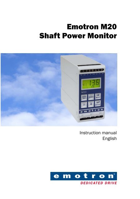
<strong>Emotron</strong> <strong>M20</strong><br />
<strong>Shaft</strong> <strong>Power</strong> <strong>Monitor</strong><br />
Instruction manual<br />
English
Contents<br />
1 Inside the Box............................................................................. 1<br />
2 Safety .......................................................................................... 2<br />
3 Description.................................................................................. 3<br />
4 Getting Started........................................................................... 5<br />
4.1 Please note ................................................................................................. 5<br />
4.2 Connection and set-up before first start................................................... 5<br />
4.3 First start ..................................................................................................... 6<br />
4.4 Manual setting of alarm levels,<br />
alternative A ................................................................................................ 7<br />
4.5 Manual setting of alarm levels,<br />
alternative B................................................................................................ 8<br />
4.6 Manual setting of alarm levels, alternative C........................................... 8<br />
5 Wiring .......................................................................................... 9<br />
5.1 Alternative example for single-phase connection ................................. 11<br />
5.2 Example - digital input............................................................................. 12<br />
6 Selection of Current Transformer ........................................... 12<br />
6.1 Motors less than 100 A........................................................................... 12<br />
6.2 Motors greater than 100 A ..................................................................... 15<br />
7 Operation .................................................................................. 17<br />
7.1 Overview................................................................................................... 17<br />
7.2 Window menu .......................................................................................... 18<br />
7.3 How to change a value............................................................................ 19<br />
8 Programming ............................................................................ 20<br />
8.1 Set measurement unit, HP or kW........................................................... 20<br />
8.1.1 Selecting the unit of measurement........................................................ 20<br />
8.2 Setting rated motor power and current (window 41 and 42)............... 22<br />
8.2.1 Programming............................................................................................ 22<br />
<strong>Emotron</strong> AB 01-2151-01r3 1
8.3 Setting number of phases (window 43).................................................. 23<br />
8.3.1 Programming ............................................................................................ 23<br />
8.4 <strong>Monitor</strong> function (window 05) ................................................................ 23<br />
8.5 Setting the Start Delay (window 31) ....................................................... 25<br />
8.6 Setting alarm levels with Auto set........................................................... 26<br />
8.7 Setting the Response Delay (windows 32<br />
and 34)...................................................................................................... 27<br />
9 Advanced Features .................................................................. 29<br />
9.1 Setting alarm levels manually (windows 11-14) .................................... 29<br />
10 Troubleshooting ....................................................................... 40<br />
11 Technical Data ......................................................................... 42<br />
12 Parameter List.......................................................................... 46<br />
13 Service ...................................................................................... 49<br />
2 <strong>Emotron</strong> AB 01-2151-01r3
1 Inside the Box<br />
Please check the delivery. Despite the fact that all products from <strong>Emotron</strong> are<br />
carefully inspected and packed, transport damage may occur:<br />
• Your shipment should contain the <strong>Emotron</strong> <strong>M20</strong> shaft power monitor,<br />
a current transformer, 2x terminal covers (option*) and this instruction<br />
manual.<br />
• Check carefully that the equipment ordered complies with the motor’s input<br />
voltage and that the current transformer rating is as stated on the delivery<br />
packaging.<br />
• Check that the contents have not been damaged during shipping.<br />
• If something is missing, or has been damaged, contact the supplier as well as<br />
the forwarding agent within 48 hours of receipt.<br />
NOTE: If in doubt contact your supplier before installing or commissioning<br />
the product.<br />
<strong>M20</strong> <strong>Shaft</strong> <strong>Power</strong> <strong>Monitor</strong><br />
*)<br />
<strong>Emotron</strong> AB 01-2151-01r3 Inside the Box 3
2 Safety<br />
• Study this manual thoroughly before installing and using the<br />
monitor.<br />
• The monitor must be installed by qualified personnel.<br />
• Always disconnect supply circuits prior to installing.<br />
• The installation must comply with standard and local regulations.<br />
• Pay special attention to the information in this chapter and the parts marked<br />
CAUTION in the Operation and Programming chapters.<br />
• Check that the monitor and the equipment are correctly connected before it<br />
is taken into use.<br />
• Should questions or uncertainties arise, please contact your local sales outlet<br />
or see chapter 13, Service.<br />
• Faults that arise due to faulty installation or operation are not covered by the<br />
warranty.<br />
NOTE: Removing or tampering with the seal on the housing will invalidate<br />
the warranty.<br />
4 Safety <strong>Emotron</strong> AB 01-2151-01r3
3 Description<br />
This instruction manual describes the installation and commissioning of the<br />
<strong>Emotron</strong> <strong>M20</strong> shaft power monitor. The <strong>Emotron</strong> <strong>M20</strong> supervises induction<br />
motor driven equipment and provides warnings when abnormal conditions are<br />
detected. It protects for example, pumps and other equipment. The <strong>M20</strong>’s ability<br />
to provide reliable monitoring and protection ensures that production equipment<br />
is optimized and expensive breakdowns and interruptions are minimized.<br />
The <strong>Emotron</strong> <strong>M20</strong> uses the motor as its own sensor and no external sensors or<br />
extra cabling are required. Due to the special method of subtracting motor<br />
power losses, the monitor is able to accurately measure the shaft power supplied<br />
by the motor to the application. This advanced technique allows the <strong>M20</strong> to<br />
monitor only the “application” load rather than the “total” motor load, which<br />
includes the varying motor losses.<br />
The shaft power is calculated by measuring motor input power, and subtracting<br />
the motor power loss calculated using a unique principle. The shaft power output<br />
is indicated on the monitor display in kW or HP, or as a percentage of rated<br />
power. Calculating shaft power gives more reliable supervision than non-linear<br />
techniques, such as current and phase angle measurements. Current measurement<br />
is only sufficient at high motor loads and phase angle only at low loads.<br />
Input power is sometimes called true or real power. Input power is linear, but<br />
ignores motor power loss.<br />
The <strong>M20</strong>’s analogue output and two relay outputs allow the combination of<br />
direct and indirect control. The unit offers high accuracy in the event of very<br />
small load variations. The analogue output signal can be used to scale the<br />
machine load to represent the actual working range.<br />
The monitor is very easy to install and set up and should be mounted on a<br />
standard DIN rail. It is also very easy to use. The “Auto set” function makes it<br />
possible to adjust the monitor automatically by pressing just one key.<br />
The <strong>M20</strong> provides complete flexibility in terms of the type of protection<br />
required for your application. You may select either overload and underload<br />
protection or simply overload with pre-alarm or underload with pre-alarm.<br />
Independent response delays can be selected for both overload and underload<br />
protection. Additional flexibility is provided in the form of programmable output<br />
relays, number of start attempts, number of reversing attempts etc.<br />
<strong>Emotron</strong> AB 01-2151-01r3 Description 5
The <strong>Emotron</strong> <strong>M20</strong> shaft power monitor offers advanced multi-function monitoring<br />
and a display for load indication and parameter setting. It is ideal for<br />
protecting many different applications including pumps in general, centrifugal<br />
pumps, magnetic pumps, screw and impeller pumps, mixers, scrapers, crushers,<br />
conveyor systems, etc.<br />
For further information, please see www.emotron.com.<br />
6 Description <strong>Emotron</strong> AB 01-2151-01r3
4 Getting Started<br />
4.1 Please note<br />
1. Pay special attention to the safety section in this manual and parts marked<br />
CAUTION.<br />
2. Check that motor/supply voltage corresponds to values on the monitor<br />
product label at the side of the unit.<br />
3. Make a note of the motor’s rated power and full load amps from its nameplate.<br />
Confirm that the current transformer supplied is of the correct size<br />
according to tables 1 and 2 in chapter 6of this manual.<br />
4.2 Connection and set-up before first start<br />
1. Connect the <strong>Emotron</strong> <strong>M20</strong> according to chapter 5 and Fig. 1.<br />
2. Make sure all safety measures have been taken and switch on the supply<br />
voltage.<br />
3. Use the NEXT key to scroll through the menu. Press and hold the ENTER key and<br />
press the<br />
NEXT<br />
key to scroll back.<br />
4. Set rated motor power and current in windows 41 and 42. Additional settings<br />
to be programmed are discussed in chapter 8.<br />
5. Set monitor function in window 05, overload and underload or only underload<br />
or only overload. See chapter 12, Parameter list, for range and default<br />
values.<br />
6. Set start delay and response delay in window 31 and 32/34.<br />
7. Compare all set values with the parameter list in chapter 12 to confirm that<br />
all relevant values are set. Advanced features will be found in chapter 9.<br />
<strong>Emotron</strong> AB 01-2151-01r3 Getting Started 7
4.3 First start<br />
CAUTION: Make sure that all safety measures have been taken before<br />
switching on the supply voltage and starting the motor/machine in order to<br />
avoid personal injury.<br />
1. Start the motor/machine and let it run at normal load, until the Start Delay<br />
has expired.<br />
AUTO<br />
2. Press SET<br />
for 3 seconds.<br />
Hint!<br />
Short-circuit the output relays during the set-up; this prevents the equipment<br />
from stopping unintentionally.<br />
More Hints!<br />
The monitor can be set in three different ways:<br />
1. Automatically by pressing the Auto set key as described above. The Auto set<br />
function performs a measurement (momentarily) of the actual load and sets<br />
relevant alarm levels for this actual load plus/minus the “margins” (Default;<br />
Max +16% and Min -16%).<br />
2. If Auto set is used as above, the margins can be re-adjusted manually (windows<br />
21-24). When the margin values are changed a new Auto set must<br />
always be performed to activate the changes and the new margins. More<br />
information is provided in chapter 9, Advanced Features.<br />
3. Manual setting of alarm levels (windows 11-14). The alarm levels can be set<br />
manually, without using the Auto set. See sections Manual setting of alarm<br />
levels, alternative A, B and C.<br />
Note: If any window parameter is manually adjusted, the display will flash<br />
the new value to indicate that a change has been made. The Enter key must<br />
be pressed for the <strong>M20</strong> to accept this new value.<br />
8 Getting Started <strong>Emotron</strong> AB 01-2151-01r3
4.4 Manual setting of alarm levels,<br />
alternative A<br />
Running and setting at normal load<br />
• Start the motor/machine or pump and let it run at normal load, until the<br />
Start Delay (window 31) has expired.<br />
• Read off the load on the monitor display, e.g. 65%, window 01 (or kW/<br />
HP).<br />
• Set the max. main alarm level to something between e.g. 70-85% in window<br />
11. This must be set to the actual application requirements, maximum load<br />
for machine/process.<br />
• Set the min. main alarm level to something between e.g. 60-45% in window<br />
14. This must also be set to the actual application requirements.<br />
See also Fig. 7 in section 8.4, Over- and underload monitor.<br />
<strong>Emotron</strong> AB 01-2151-01r3 Getting Started 9
4.5 Manual setting of alarm levels,<br />
alternative B<br />
Running and setting at maximum load as well as at<br />
minimum load<br />
• Start the motor/machine or pump and let it run at maximum load, until the<br />
Start Delay has expired. E.g. fill the conveyor with maximum allowed goods.<br />
• Read off the load on the monitor display, e.g. 85% (window 01).<br />
• Set the max. main alarm level to something between e.g. 90-95% in window<br />
11. This must be set to the actual application requirements, maximum load<br />
for both machine and processes.<br />
• Then run the motor/machine and let it run at minimum load, e.g. idling,<br />
until the Start Delay has expired.<br />
• Read off the load on the monitor display, e.g. 30%.<br />
• Set the min. main alarm level to something between e.g 25-20% in window<br />
14. This must also be set to the actual application requirements.<br />
See also Fig. 7 in section 8.4, Over- and underload monitor.<br />
4.6 Manual setting of alarm levels, alternative<br />
C<br />
It is also possible to approximately calculate or estimate the alarm levels. If e.g.<br />
the motor used is 22 kW, 22 must be set in window 41. This means that each<br />
percentage point corresponds to 220 W (22 kW/100 = 220 W), and the alarm<br />
limits in window 11- 14 can be set in steps of 220 W. If the max. alarm level is<br />
set to 80% in this example, the monitor will emit an alarm and stop the<br />
machine at approx. max. 17.6 kW shaft output power.<br />
NOTE: If the pre-alarm is not used, the values for Min. pre-alarm and Max.<br />
pre-alarm can be set to 0 (window 13) and 125% (window 12) respectively.<br />
This will eliminate pre-alarm warning indications in the monitor display<br />
when not in use.<br />
See also Setting alarm levels manually in chapter 9, Advanced Features.<br />
10 Getting Started <strong>Emotron</strong> AB 01-2151-01r3
5 Wiring<br />
The following wiring diagram provides an example of how the <strong>M20</strong> can be connected<br />
to control the start/stop circuit of a three-phase motor, Fig. 1. Connections<br />
to a single-phase motor are described later in this manual (Fig. 2) as are the<br />
programming changes necessary for such applications. The default setting for<br />
the <strong>M20</strong> is 3-phase.<br />
1. The current transformer CTMxxx must be placed in the same phase that is<br />
connected to terminal 9, phase L1, see Fig. 1. Failure to follow this requirement<br />
will result in the monitor failing to function.<br />
2. For single-phase connection see fig 2.<br />
When using DC voltage, terminal 6 should be connected to negative polarity<br />
(ground) and terminal 5 to positive polarity (max. 48 VDC). See also Alternative<br />
auxiliary circuit (Fig. 16) in chapter 9.<br />
Note: The current transformer (CTMxxx) must be placed in the same phase<br />
that is connected to terminal 9, phase L1, see Fig. 1.<br />
<strong>Emotron</strong> AB 01-2151-01r3 Wiring 11
V<br />
L1<br />
L2<br />
L3<br />
NOTE: In power<br />
down, both relays<br />
are always N.O.<br />
9 L1<br />
3<br />
4<br />
A+ A-<br />
11<br />
L2<br />
<strong>M20</strong><br />
13<br />
L3<br />
S1 S2<br />
1<br />
2<br />
C<br />
R1<br />
R2<br />
6<br />
7<br />
8<br />
DIG 5<br />
Max. 240 VAC (alt. 0 VDC-)<br />
CTMxxx<br />
K1<br />
Please see CTM<br />
information<br />
on Page 9.<br />
N (48VDC+)<br />
<strong>Monitor</strong> voltage see “Note” below.<br />
K1<br />
U<br />
W<br />
M<br />
NOTE: <strong>Monitor</strong> Max. 240VAC (48VDC-)<br />
-Reset<br />
voltage see<br />
-Auto set<br />
Note below. {<br />
- Block<br />
PRE-<br />
ALARM<br />
K1<br />
N (alt. 48 VDC+)<br />
Fig. 1<br />
Connection example<br />
NOTE: If the START/STOP is connected as per Fig. 1, it is recommended that<br />
terminals 6 and 7 be bypassed during programming. After the programming<br />
is completed the bypass must be taken out. In Fig. 1 make sure that the<br />
monitor voltage range e.g. 3x380-500 VAC matches the connected motor/<br />
line voltage, e.g. 3x 400 V.<br />
Please use the enclosed plastic (rubber) insert (if ordered, optional) to cover the<br />
monitor terminals.<br />
12 Wiring <strong>Emotron</strong> AB 01-2151-01r3
5.1 Alternative example for single-phase<br />
connection<br />
This wiring example shows the connections required for single-phase applications.<br />
Refer to Fig. 1 for the remaining wiring.<br />
L1<br />
N<br />
CTMxxx<br />
9<br />
11<br />
13<br />
L1<br />
L2<br />
L3<br />
A+<br />
S1<br />
A-<br />
<strong>M20</strong><br />
3<br />
4<br />
S2<br />
1<br />
2<br />
C<br />
R1<br />
R2<br />
DIG<br />
6<br />
7<br />
8<br />
5<br />
K1<br />
NOTE: <strong>Monitor</strong><br />
voltage, see<br />
note below.<br />
L<br />
N<br />
M<br />
Fig. 2<br />
Single-phase connection example.<br />
NOTE: In Fig. 2 make sure that the monitor voltage range e.g. 1x100-240 VAC<br />
matches the connected motor/“line – neutral” voltage, e.g. 1x 230 V.<br />
<strong>Emotron</strong> AB 01-2151-01r3 Wiring 13
5.2 Example - digital input<br />
The digital input uses terminals 5 (DIG) and 6 (C - reference). Either a VAC or<br />
a VDC signal may be used. Connect + to terminal 5 (DIG) and - to terminal 6<br />
for VDC signal. Please note the polarity when DC voltage is used. See also Fig1<br />
and terminal 6: Max. 240 VAC (or 0 VDC-) and on terminal 5: N<br />
(or 48 VDC+). See also chapter 9, Advanced Features.<br />
VAC<br />
<strong>M20</strong><br />
VDC<br />
6<br />
C ~<br />
C<br />
5 Max 240 VAC<br />
<strong>M20</strong><br />
DIG ~ DIG<br />
6<br />
5<br />
+ -<br />
Max 48 VDC<br />
Note polarity!<br />
Fig. 3<br />
Wiring example for digital input.<br />
6 Selection of Current Transformer<br />
6.1 Motors less than 100 A<br />
1. Check the rated motor current on the motor plate.<br />
2. Compare this value with the current in Table 1.<br />
3. From Table 1, select the current transformer and the appropriate number of<br />
windings.<br />
Fig. 5 shows the different types of current transformer (CT) windings. In Fig.<br />
5:1 the motor wire is just drawn through the CT, in the text and tables below<br />
this is described as 1 (one) winding. Fig. 5:2 shows a CT with 2 windings and<br />
Fig. 5:3, 3 windings. In other words the number windings is equal to the<br />
number of times the motor wire “L1” is drawn through the hole of the current<br />
transformer.<br />
NOTE: Maximum length of the CTM cable is 1 m (39 inches).<br />
14 Selection of Current Transformer <strong>Emotron</strong> AB 01-2151-01r3
Example<br />
• Rated motor current = 12 A.<br />
• Select 10.1-12.5 A from the first column in Table 1.<br />
• This gives:<br />
CTM025 with 2 windings (the motor wire is drawn through the CT’s hole<br />
twice).<br />
Table 1<br />
CT less than 100 A<br />
RATED MOTOR<br />
CURRENT [A]<br />
CURRENT TRANSFORMER TYPE and<br />
NUMBER OF WINDINGS<br />
CTM 010 CTM 025 CTM 050 CTM 100<br />
0.4 – 1.0 10<br />
1.01 – 2.0 5<br />
2.01 – 3.0 3<br />
3.1 – 5.0 2<br />
5.1 – 10.0 1<br />
10.1 – 12.5 2<br />
12.6 –25.0 1<br />
26.0 – 50.0 1<br />
51.0 – 100.0 1<br />
In order to ensure an accurate calibration of the <strong>M20</strong>, it is essential that you use<br />
the correct CTM and apply the exact number of windings in accordance with<br />
the above table.<br />
NOTE: Normally the appropriate Current Transformer (CT) will have been<br />
ordered and shipped with the <strong>M20</strong>. Check that this is the case; contact the<br />
supplier if in doubt.<br />
<strong>Emotron</strong> AB 01-2151-01r3 Selection of Current Transformer 15
L1<br />
L2<br />
L3<br />
CTM025<br />
2 windings<br />
P2<br />
1 2<br />
S1 S2<br />
<strong>M20</strong><br />
M<br />
3<br />
Fig. 4<br />
Example CTM 025 with 2 windings for a 12 A motor<br />
NOTE: The current transformer connection and orientation are not polarity<br />
sensitive, but must be connected to the same phase that is being<br />
referenced for terminal 9 of the <strong>M20</strong>.<br />
P2<br />
1 2<br />
5:1 5:2 5:3<br />
Fig. 5<br />
Example 1, 2 and 3 windings.<br />
16 Selection of Current Transformer <strong>Emotron</strong> AB 01-2151-01r3
6.2 Motors greater than 100 A<br />
1. Check the rated motor current on the motor plate.<br />
2. Compare this value with the current in Table 2.<br />
3. Select the primary and secondary current transformer and the appropriate<br />
number of windings from the columns in Table 2.<br />
Please note that the ratio of the primary transformer must be exactly as provided<br />
in the table below, otherwise the monitor power calculations will be inaccurate.<br />
This will affect power readings, settings etc.<br />
Example<br />
• Rated motor current = 260 A.<br />
• Select 251-500 A from the first column in Table 2.<br />
• This gives:<br />
- Primary transformer 500:5, 1 winding. (The motor wire is drawn through<br />
the primary transformer once).<br />
- CTM010 with 2 windings. (The wire from the primary transformer is<br />
drawn through the hole in the CT, "CTM10", twice).<br />
Table 2 CT greater than 100 A.<br />
RATED MOTOR<br />
CURRENT [A]<br />
101 – 150<br />
151 – 250<br />
251 – 500<br />
501 – 999<br />
CURRENT TRANSFORMER TYPE and<br />
NUMBER OF PRIMARY WINDINGS<br />
150:5 + CTM 010<br />
1 + 2<br />
250:5 + CTM 010<br />
1 + 2<br />
500:5 + CTM 010<br />
1 + 2<br />
1000:5 + CTM 010<br />
1 + 2<br />
NOTE: Check that the appropriate Current Transformer (CT) has been<br />
ordered and shipped with the <strong>M20</strong>. Contact the supplier if in doubt.<br />
<strong>Emotron</strong> AB 01-2151-01r3 Selection of Current Transformer 17
L1<br />
L2<br />
L3<br />
CTM010<br />
2 windings<br />
P2<br />
1 winding<br />
1 2<br />
S1<br />
S2<br />
S1 S2<br />
500:5<br />
<strong>M20</strong><br />
M<br />
3<br />
Fig. 6<br />
Example of a CTM 010 with 2 windings and a primary transformer<br />
500:5 with 1 winding for a 260 A motor.<br />
NOTE: The transformer connection and orientation are not polarity sensitive,<br />
but must be connected to the same phase that is being referenced for<br />
terminal 9 of the <strong>M20</strong>.<br />
18 Selection of Current Transformer <strong>Emotron</strong> AB 01-2151-01r3
7 Operation<br />
Make sure the enclosed plastic (rubber) insert (if ordered, optional) covers the<br />
monitor terminals before you start programming.<br />
7.1 Overview<br />
Control Terminals<br />
1 S1 Current transformer input<br />
2 S2 Current transformer input<br />
3 + Analogue output<br />
4 - Analogue output<br />
5 DIG External RESET or AUTO SET<br />
or Block Pre-Alarm<br />
6 C Common: RELAY, DIG<br />
7 R1 Main Alarm Relay 1*<br />
8 R2 Pre-Alarm Relay 2<br />
AUTO SET Key<br />
Press for 3 seconds during<br />
normal and stable load to<br />
apply the automatic setting of<br />
the alarm levels. Not available<br />
if Parameter Locked.<br />
12<br />
123<br />
%<br />
LCD<br />
12 Function (window) number<br />
123 Function Value<br />
! Warning signal<br />
Start, response delay or<br />
block timer active<br />
Parameter locked<br />
V Voltage indicator<br />
A Current indicator<br />
mA Milliampere indicator<br />
kW Kilowatt indicator<br />
S Second indicator<br />
% Per cent indicator<br />
NEXT Key<br />
Proceeds to next window. If no<br />
key is pressed for 1 minute the<br />
display returns to window 01<br />
automatically. Scroll back by<br />
pressing and holding [ENTER]<br />
at the same time as the next<br />
key is pressed.<br />
RESET Key<br />
To reset ALARM<br />
+/- Keys<br />
For increasing and<br />
decreasing value<br />
<strong>Monitor</strong> Supply Terminals<br />
9 L1 Motor phase<br />
11 L2 Motor phase<br />
13 L3 Motor phase<br />
* For alternative relay function, see Special functions<br />
in chapter 9.<br />
ENTER Key<br />
Confirm (save) changes.<br />
After <strong>Power</strong> up window 01<br />
appears, the actual load value<br />
is shown.<br />
Default view (example shows<br />
54% load):<br />
01<br />
54<br />
%<br />
Use the NEXT key to scroll<br />
through the function menu.<br />
<strong>Emotron</strong> AB 01-2151-01r3 Operation 19
7.2 Window menu<br />
Alarm indication<br />
00<br />
Start window<br />
01<br />
Measured shaft power<br />
02<br />
Measured line voltage<br />
03<br />
Measured current<br />
04<br />
Parameter Lock<br />
05<br />
<strong>Monitor</strong> Function<br />
Factory defaults<br />
99<br />
11 11<br />
MAX Main Alarm<br />
Analogue Output<br />
Block Timer<br />
Digital Input<br />
Relay function<br />
91<br />
82<br />
81<br />
65*<br />
OVER- and UNDERLOAD<br />
12 12<br />
13<br />
13<br />
14 14<br />
21<br />
OVERLOAD<br />
21<br />
22 22<br />
UNDERLOAD<br />
MAX Pre-Alarm<br />
MIN Pre-Alarm<br />
MIN Main Alarm<br />
MAX Main Alarm margin<br />
MAX Pre-Alarm margin<br />
Pre-Alarm Relay 2<br />
64<br />
23<br />
23<br />
MIN Pre-Alarm margin<br />
Main Alarm Relay 1<br />
63<br />
24<br />
24<br />
MIN Main Alarm margin<br />
Alarm at no motor<br />
current<br />
Main Alarm Latch<br />
62<br />
61<br />
31<br />
Start Delay<br />
Number Of Phases<br />
43<br />
32<br />
Response Delay Max<br />
Rated Current<br />
42<br />
33<br />
Hysteresis<br />
Rated Motor <strong>Power</strong><br />
41<br />
34<br />
Response Delay Min<br />
35*<br />
Pause/Reverse time<br />
36*<br />
Autoreset (start attempts)<br />
* See Special functions in chapter 9, Advanced Features<br />
20 Operation <strong>Emotron</strong> AB 01-2151-01r3
• The Alarm window 00 only appears if an Alarm output is active.<br />
• The Actual Load window 01 appears after power up.<br />
• Use the NEXT key to scroll through the menu. Scroll back by pressing and<br />
holding ENTER at the same time as the NEXT key is pressed.<br />
• The Actual Load window (or alternative alarm window) will appear automatically<br />
if no keys are pressed for longer than 1 minute.<br />
• If the Parameter Lock is on, only windows 00 (if alarm active)<br />
01 02 03 04 are visible.<br />
• Window 05 selects the monitor function, see section 8.4.<br />
7.3 How to change a value<br />
Example: setting the rated motor current in window 42.<br />
1. Press<br />
NEXT<br />
until the window number 42 appears.<br />
5.6<br />
42<br />
A<br />
23<br />
2. Press or until the desired value is reached (e.g. 23 A), value flashes.<br />
42<br />
A<br />
ENTER<br />
3. Press to confirm and save the change, value stops flashing.<br />
NOTE: If the value is NOT to be changed, press the<br />
NEXT<br />
key.<br />
CAUTION: In order to avoid personal injury, make sure that all safety<br />
measures have been taken before switching on the supply voltage and<br />
starting the motor/machine.<br />
<strong>Emotron</strong> AB 01-2151-01r3 Operation 21
8 Programming<br />
8.1 Set measurement unit, HP or kW<br />
8.1.1 Selecting the unit of measurement<br />
The unit of measurement can be set to kilowatts or horsepower both as absolute<br />
or relative values. This setting is valid for the alarm levels, rated motor power<br />
and the actual load read-out in window 01.<br />
Measurement<br />
unit<br />
Read-out<br />
load<br />
window 01<br />
Rated power<br />
window 41<br />
Alarm levels<br />
windows<br />
11, 12, 13, 14<br />
Kilowatt relative value (def.)* % kW %<br />
Horsepower absolute value HP HP HP<br />
Horsepower relative value* % HP %<br />
Kilowatt absolute value kW kW kW<br />
* Measured shaft power as % of rated power.<br />
CAUTION: In order to avoid personal injury, make sure that all safety<br />
measures have been taken before switching on the supply voltage and<br />
starting the motor/machine.<br />
22 Programming <strong>Emotron</strong> AB 01-2151-01r3
Programming<br />
1. Go to window 01.<br />
2. Press and hold and simultaneously for 3 seconds.<br />
3. The next unit of measurement is set and appears for 2 sec (see examples).<br />
Repeat to select the desired measurement unit according to the table.<br />
Horsepower:<br />
absolute value<br />
For 2 seconds<br />
HP<br />
Read-out example<br />
01<br />
3.52<br />
Horsepower:<br />
relative value*<br />
HP<br />
%<br />
01<br />
12<br />
%<br />
Kilowatt:<br />
absolute value<br />
kW<br />
01<br />
4.62<br />
kW<br />
Kilowatt:<br />
relative value*<br />
(default)<br />
kW<br />
%<br />
01<br />
12<br />
%<br />
*Measured shaft power as % of rated power.<br />
<strong>Emotron</strong> AB 01-2151-01r3 Programming 23
8.2 Setting rated motor power and current<br />
(window 41 and 42)<br />
The rated motor power and the rated motor current must be set in windows 41<br />
and 42.<br />
Example motor plate:<br />
TYPE: T56BN/4 NR: 948287 Prot. IP: 54<br />
Serv: S1 Cos ϕ: 0.78 Is. Cl:F<br />
V:Y/Δ Hz HP kW RPM A:Y/Δ<br />
240/415 50 3 2.2 1400 5.6/9.4<br />
260/440 60 3 2.2 1680 5.8/9.1<br />
ASYNCHRONOUS THREE-PHASE MOTORS<br />
8.2.1 Programming<br />
1. Go to window 41 (default = 2.2 kW).<br />
2. Press or to set the rated motor power as indicated on the motor<br />
plate (see example).<br />
3. Press<br />
ENTER<br />
to confirm the change.<br />
4. Go to window 42 (default = 5.6 A).<br />
5. Press or to set the rated motor current as indicated on the motor<br />
plate (see example).<br />
6. Press<br />
ENTER<br />
to confirm the change.<br />
24 Programming <strong>Emotron</strong> AB 01-2151-01r3
8.3 Setting number of phases (window 43)<br />
The number of phases must be set according to the number of motor phases.<br />
Default is 3 phases, see also chapter 5, Wiring.<br />
8.3.1 Programming<br />
1. Go to window 43 (default = 3PH).<br />
43<br />
3PH<br />
2. Press or to set the number of phases to 1 if a single-phase motor is<br />
used.<br />
3. Press<br />
ENTER<br />
to confirm the change.<br />
43<br />
1PH<br />
8.4 <strong>Monitor</strong> function (window 05)<br />
<strong>Monitor</strong><br />
(Protection)<br />
Indication in<br />
window 05<br />
Alarm<br />
Output Relay<br />
(default)<br />
OVER- and UNDER-<br />
LOAD (default)<br />
OVERLOAD<br />
UNDERLOAD<br />
MAX Main Alarm Relay 1 (NC): 6-7<br />
MAX Pre-Alarm Relay 2 (NO): 6-8<br />
MIN Pre-Alarm Relay 2 (NO): 6-8<br />
MIN Main Alarm Relay 1 (NC): 6-7<br />
MAX Main Alarm Relay 1 (NC): 6-7<br />
MAX Pre-Alarm Relay 2 (NO): 6-8<br />
MIN Pre-Alarm Relay 2 (NO): 6-8<br />
MIN Main Alarm Relay 1 (NC): 6-7<br />
If separate output relays are required for overload and underload alarms, please<br />
refer to chapter 9 and chapter 12.<br />
<strong>Emotron</strong> AB 01-2151-01r3 Programming 25
Overload and underload <strong>Monitor</strong><br />
P/%<br />
START UNDERLOAD OVERLOAD<br />
MAX Main alarm<br />
level [11]<br />
MAX Pre-alarm<br />
level [12]<br />
AUTOSET level<br />
Normal load<br />
OPERATION AREA<br />
MAX Pre-alarm<br />
margin [22]<br />
MAX Main<br />
alarm margin<br />
[21]<br />
MIN Pre-alarm<br />
level [13]<br />
MIN Pre-alarm<br />
margin [23]<br />
MIN Main<br />
alarm margin<br />
[24]<br />
MIN Main alarm<br />
level [14]<br />
Response<br />
delay<br />
[34] [32]<br />
t/s<br />
Start delay [31]<br />
Main Alarm latch=ON [61]<br />
Relay 1<br />
Main alarm<br />
Relay 2<br />
Pre-alarm<br />
Fig. 7<br />
Overload and underload monitor.<br />
Programming<br />
1. Go to window 05. The default selection is Overload and Underload monitor.<br />
2. Press or to select underload or overload monitor.<br />
05<br />
_ _ 05<br />
_<br />
05<br />
_<br />
OVER- and UNDERLOAD UNDERLOAD OVERLOAD<br />
3. Press<br />
ENTER<br />
to confirm the change.<br />
26 Programming <strong>Emotron</strong> AB 01-2151-01r3
8.5 Setting the Start Delay (window 31)<br />
To avoid false alarms during start up a Start Delay must be set to allow the<br />
motor and machine to speed up and to allow the power in-rush currents.<br />
Programming<br />
1. Determine in seconds how long it takes for the motor and machine to reach<br />
speed and for the power in-rush to pass. This will be the Start Delay.<br />
2. Go to window 31 (default = 2.0 s).<br />
3. Press or to set the determined Start Delay time in seconds.<br />
4. Press<br />
ENTER<br />
to confirm the change.<br />
If the monitor is being used on a self-priming pump, it may also be necessary to<br />
set the Start Delay long enough to allow the pump to become fully primed.<br />
Example: Start Delay 2.0 s<br />
31<br />
2.0<br />
S<br />
P<br />
t<br />
Start Delay [31]<br />
Fig. 8<br />
Start Delay.<br />
<strong>Emotron</strong> AB 01-2151-01r3 Programming 27
8.6 Setting alarm levels with Auto set<br />
The Auto set command performs a measurement (momentarily) of the actual<br />
motor load and automatically sets the relevant alarm levels depending on the<br />
selected monitor function.<br />
Protection<br />
(<strong>Monitor</strong><br />
function<br />
window 05)<br />
Alarm<br />
Margin<br />
Value<br />
(Default<br />
margins)<br />
Margins<br />
(Windows)<br />
Alarm Level at<br />
Auto set<br />
MAX Main<br />
Alarm<br />
16%<br />
21: MAX Main<br />
Alarm margin<br />
Normal machine<br />
load + Window 21<br />
OVER- and<br />
UNDERLOAD<br />
(Default)<br />
MAX Pre-<br />
Alarm<br />
MIN Pre-<br />
Alarm<br />
8%<br />
8%<br />
22: MAX Pre-<br />
Alarm margin<br />
23: MIN Pre-<br />
Alarm margin<br />
Normal machine<br />
load + Window 22<br />
Normal machine<br />
load - Window 23<br />
MIN Main<br />
Alarm<br />
16%<br />
24: MIN Main<br />
Alarm margin<br />
Normal machine<br />
load - Window 24<br />
OVERLOAD<br />
MAX Main<br />
Alarm<br />
MAX Pre-<br />
Alarm<br />
16%<br />
8%<br />
21: MAX Main<br />
Alarm margin<br />
22: MAX Pre-<br />
Alarm margin<br />
Normal machine<br />
load + Window 21<br />
Normal machine<br />
load + Window 22<br />
UNDERLOAD<br />
MIN Pre-<br />
Alarm<br />
MIN Main<br />
Alarm<br />
8%<br />
16%<br />
23: MIN Pre-<br />
Alarm margin<br />
24: MIN Main<br />
Alarm margin<br />
Normal machine<br />
load - Window 23<br />
Normal machine<br />
load - Window 24<br />
Programming<br />
1. Start the motor and let it run at the normal machine load until the Start<br />
Delay has expired.<br />
AUTO<br />
2. Press SET<br />
for 3 seconds. This can be done in any window.<br />
28 Programming <strong>Emotron</strong> AB 01-2151-01r3
3. The display shows “SEt”, to confirm that the Auto set level has been measured<br />
and the alarm levels have been set. The display reverts to window 01.<br />
3 seconds<br />
AUTO<br />
SET<br />
SEE<br />
01<br />
40<br />
%<br />
4. If the alarm levels are too high or too low, readjust the appropriate MAR-<br />
GINS (see table above) and perform a new Auto set. Alternatively, alarm levels<br />
can be set manually, see chapter 9.<br />
8.7 Setting the Response Delay (windows 32<br />
and 34)<br />
A Response Delay allows the machine to remain in an over- or underload condition<br />
for a specific time before the alarm relays are activated. Set the response<br />
delay for the overload condition in window 32 (max.), and set the response<br />
delay for the underload condition in window 34 (min.). The default value for<br />
both windows are 0.5 s. The valves may be adjusted upwards to avoid triggering<br />
a “false alarm”.<br />
Programming<br />
1. Determine in seconds the response delay required for both overload and<br />
underload conditions. This is normally determined by the unique properties<br />
and behaviour of each application.<br />
2. Go to window 32 (overload, default = 0.5 s).<br />
3. Press or to set the determined Response Delay time in seconds.<br />
4. Press<br />
ENTER<br />
to confirm the change.<br />
The response delay for the underload condition (min.) is set in window 34 in a<br />
similar way.<br />
<strong>Emotron</strong> AB 01-2151-01r3 Programming 29
Example: Response Delay<br />
32<br />
0.5<br />
P<br />
S<br />
34<br />
0.5<br />
S<br />
Alarm level<br />
Response Delay [32]<br />
t<br />
Alarm<br />
Fig. 9<br />
Response Delay.<br />
30 Programming <strong>Emotron</strong> AB 01-2151-01r3
9 Advanced Features<br />
9.1 Setting alarm levels manually (windows 11-<br />
14)<br />
The alarm levels can be set manually, without using the Auto set. These levels<br />
can also be readjusted, e.g. for fine-turning, after an Auto set has been performed.See<br />
also section 4.3 to 4.6.<br />
Protection (<strong>Monitor</strong> function<br />
window 05)<br />
Alarm levels (Window)<br />
Default<br />
OVER- and UNDERLOAD<br />
(Default)<br />
OVERLOAD<br />
UNDERLOAD<br />
11: MAX Main Alarm 100%<br />
12: MAX Pre-Alarm 100%<br />
13: MIN Pre-Alarm 0%<br />
14: MIN Main Alarm 0%<br />
11: MAX Main Alarm 100%<br />
12: MAX Pre-Alarm 100%<br />
13: MIN Pre-Alarm 0%<br />
14: MIN Main Alarm 0%<br />
<strong>Emotron</strong> AB 01-2151-01r3 Advanced Features 31
Setting margins (windows 21-24)<br />
The margins for the Auto set can be changed manually. After the adjustment,<br />
the Auto set action must be performed again.<br />
Protection (<strong>Monitor</strong> function<br />
window 05)<br />
Window<br />
Default<br />
OVER- and UNDERLOAD<br />
(Default)<br />
OVERLOAD<br />
UNDERLOAD<br />
21: MAX Main Alarm margin 16%<br />
22: MAX Pre-Alarm margin 8%<br />
23: MIN Pre-Alarm margin 8%<br />
24: MIN Main Alarm margin 16%<br />
21: MAX Main Alarm margin 16%<br />
22: MAX Pre-Alarm margin 8%<br />
23: MIN Pre-Alarm margin 8%<br />
24: MIN Main Alarm margin 16%<br />
Setting hysteresis (window 33)<br />
The hysteresis of an alarm level prevents the alarm relay “chattering” if the load<br />
fluctuates even in a normal “stable” condition. This also pplies to a pre-alarm.<br />
This feature is normally only used if the main alarm latch (window 61) is set to<br />
Off. Default = 0%.<br />
P/%<br />
MAX Main Alarm level [11]<br />
Hysteresis [33]<br />
MIN Main Alarm level [14]<br />
t/s<br />
Relay 1 MAIN Alarm<br />
Fig. 10 Hysteresis<br />
32 Advanced Features <strong>Emotron</strong> AB 01-2151-01r3
Setting main alarm latch (window 61)<br />
The main alarm latch keeps the main alarm output active, even if the alarm condition<br />
has been removed. A latched alarm output can be reset by:<br />
• The reset key<br />
• External reset via digital input (see window 81).<br />
• Switching off the power to the monitor (see also Wiring).<br />
Default=Off.<br />
Setting alarm at no motor current (window 62)<br />
The alarm at no motor current gives an alarm if the motor current goes down to<br />
zero (62=on). Default=Off (No alarm at no motor current).<br />
Setting relay output (window 63 and 64 alt. 65)<br />
The relay outputs R1 and R2 can be set to NO or NC contacts.<br />
NOTE: If the power to the load monitor is switched off, the relay contacts<br />
are always in position NO.<br />
If separate output relays are required for overload (max., relay R1) and underload<br />
(min., relay R2), see Special functions in chapter 9 and chapter 12.<br />
Setting digital input (window 81)<br />
The digital input can be set for:<br />
RES: External RESET<br />
(Default)<br />
AU: External Auto set<br />
bLo: Block Pre-Alarm<br />
To reset an alarm.<br />
To perform an Auto set with an external signal.<br />
To block the Pre-Alarm function and start the Block<br />
timer. If the input is high a Pre-Alarm is blocked, i.e. it is<br />
neglected. See also window 82.<br />
<strong>Emotron</strong> AB 01-2151-01r3 Advanced Features 33
Setting block timer (Window 82)<br />
To set the timer for the blocking time after the Block command is released (see<br />
also window 81). Default = 0.0 sec.<br />
P/%<br />
MAX Main Alarm level [11]<br />
MAX Pre-Alarm level [12]<br />
Auto set level<br />
t/s<br />
Relay 1 Main alarm<br />
Relay 2 Pre-alarm<br />
Pre-Alarm Blocked<br />
Block signal high on terminal 5 DIG [81] Block timer [82]<br />
Fig. 11 Block timer<br />
Setting analogue output (window 91)<br />
The analogue output provides an analogue signal of either 0-20 mA or 4-20 mA<br />
which represents the motor shaft power. The signal can be inverted (20-0 or 20-<br />
4 mA). Full scale: rated motor power, see Fig. 12. To set P-span/scaling (full<br />
scale) see Fig. 13.<br />
34 Advanced Features <strong>Emotron</strong> AB 01-2151-01r3
91<br />
4.20<br />
P SHAFT<br />
100%<br />
20.4<br />
20.0<br />
0.20<br />
0%<br />
4.20<br />
0 4 20<br />
Output<br />
mA<br />
Fig. 12<br />
<strong>Emotron</strong> AB 01-2151-01r3 Advanced Features 35
Setting analogue output load range: P-span (window 92-<br />
93)<br />
With windows 92 and 93 the full scale of the analogue output can be set according<br />
to the minimum and maximum load (P-span).<br />
1. In window 91, press RESET and + for two seconds until “on” shows. Windows<br />
92 and 93 are now active.<br />
100%<br />
70%<br />
P shaft<br />
92= 20%<br />
93= 70%<br />
92= 0%<br />
93= 100%<br />
20%<br />
0<br />
0 6 14 20<br />
Fig. 13<br />
Output<br />
mA<br />
2. Set the lowest load value in window 92 (e.g. 20%)<br />
3. Set the highest load value in window 93 (e.g. 70%)<br />
The full scale of the analogue output is now set between 20% and 70% load.<br />
See Fig. 13. To deactivate: Press RESET and + for two seconds until Off shows<br />
in window 91.Windows 92 and 93 are now inactive.<br />
Locking parameters (window 04)<br />
To avoid the parameter settings being changed unintentionally, the programming<br />
can be locked by entering the code “369” in window 04. Now only Load<br />
[01], Voltage [02] and Current [03] can be checked. Follow the same procedure<br />
36 Advanced Features <strong>Emotron</strong> AB 01-2151-01r3
to unlock the monitor. The Auto set key is disabled when parameters are locked.<br />
Auto set via digital input is always active if window 81 is set to AU (Auto set).<br />
01<br />
<br />
24<br />
NOTE: The<br />
%<br />
<br />
symbol appears in all windows.<br />
Resetting to factory defaults (window 99)<br />
The factory defaults are reset by entering “dEF” in window 99. If window 99<br />
shows “USr” it indicates that the settings have been changed to user specific settings.<br />
View alarm message (window 00)<br />
In an alarm condition, the window 00 appears automatically. The window indicates<br />
the following alarm conditions. Window 00 flashes at all times.<br />
!<br />
F<br />
00 ^<br />
Pre-Alarm MAX<br />
level reached<br />
!<br />
00<br />
LU<br />
Undervoltage,<br />
switch off the<br />
supply!<br />
!<br />
Alarm MAX<br />
level reached<br />
00 F^ 00 0U<br />
!<br />
Overvoltage,<br />
switch off the<br />
supply!<br />
!<br />
Pre-Alarm MIN<br />
level reached<br />
00 FO<br />
00 F0<br />
!<br />
No motor current<br />
Window 62 = on<br />
!<br />
Alarm MIN<br />
level reached<br />
00 FO<br />
01 OOO<br />
!<br />
Out Of Range. This message<br />
appears only in window 01 (actual<br />
load) or 03 (actual current)<br />
When the monitor is switched on (power up), the voltage on phases L1, L2 and<br />
L3 is checked. If the wrong voltage is detected, an LU (undervoltage) or OU<br />
(overvoltage) alarm is generated. No relay alarm will be indicated or activated.<br />
<strong>Emotron</strong> AB 01-2151-01r3 Advanced Features 37
Special functions (windows 35, 36 and 65)<br />
Special functions are separate relays for overload and underload alarm/stop, start<br />
attempts and a reverse function with start attempts:<br />
• Window 65 = 0, Normal <strong>M20</strong><br />
• Window 65 = 1, Separate relays for overload and underload alarm (DLM)<br />
• Window 65 = 2, Reverse function<br />
Window 65=0<br />
“Normal <strong>M20</strong>”<br />
Window 65=1<br />
“Separate relays<br />
over-/underload<br />
alarm” (max/min)<br />
Window 65=2<br />
“Reverse function”<br />
R1<br />
Max/Min<br />
Main alarm<br />
R1<br />
Max<br />
Main alarm<br />
R1<br />
Forward<br />
R2<br />
Max/Min<br />
Pre-alarm<br />
R2<br />
Min<br />
Main alarm<br />
R2<br />
Reverse<br />
Fig. 14 Window 65 and relay functions<br />
In all three cases the number of start attempts after a main alarm may be set in<br />
window 36. The pause time between start attempts may be set in window 35.<br />
This time is also used as the time to run the motor in the reverse direction when<br />
window 65=2. If a “jam” occurs on the reverse direction the <strong>M20</strong> will stop the<br />
motor immediately and no more start attempts will be made until the alarm is<br />
reset.<br />
The reverse function can be used to reverse e.g. a screw conveyor or pump when<br />
a “jum” occurs. Reversing the motor may remove the blockage. Should one<br />
reverse cycle not be enough to release the material, the <strong>M20</strong> will repeat this<br />
operation up to a maximum of 5 cycles (window 36, 0-5 start attempts). Relay<br />
R1=forward, relay R2=reverse.<br />
NOTE: For special handling of analogue output in reverse mode, see below.<br />
The analogue output will go to its maximum e.g. 20 mA when the number of<br />
allowed start attempts has elapsed. Or if an overload condition occurs in reverse<br />
direction (window 65=2).<br />
38 Advanced Features <strong>Emotron</strong> AB 01-2151-01r3
Resetting an alarm<br />
A reset will cause the start attempt counter to be reset (new start attempts may<br />
be performed).<br />
NOTE: In order to accomplish the above result, it will be necessary for a<br />
forward and reversing motor starter to be installed. See Fig. 15 Example of<br />
connection with a forward and reversing motor starter (contactor).<br />
<strong>Emotron</strong> AB 01-2151-01r3 Advanced Features 39
L1<br />
L2<br />
L3<br />
}<br />
Alarm/Stop<br />
20 mA<br />
(Blocking)<br />
CTMx<br />
9<br />
L1<br />
11<br />
L2<br />
13<br />
L3<br />
A+<br />
A-<br />
<strong>M20</strong><br />
S1 S2<br />
3<br />
4<br />
1<br />
2<br />
C<br />
R1<br />
R2<br />
DIG<br />
6<br />
7<br />
8<br />
5<br />
Max 240 VAC (alt. 0 VDC-)<br />
K1<br />
K2 K1 K2 Reset<br />
FWD<br />
REV<br />
N (alt. 48 VDC+)<br />
Window Function Range<br />
M<br />
U<br />
V<br />
W<br />
35 Reverse time 3-90 s<br />
36 Start attempts 0-5<br />
65 Relay function 2=reverse<br />
Fig. 15 Example of connection with a forward and reversing motor starter (contactor).<br />
NOTE: In Fig. 15, R1 and R2 (K1 and K2) must not be energized/on at the<br />
same time as this will generate a short circuit. Therefore it is important<br />
that window 65 = 2 before the relays are connected to the contactors.<br />
40 Advanced Features <strong>Emotron</strong> AB 01-2151-01r3
Alternative auxiliary circuit<br />
L1<br />
L2<br />
L3<br />
CTMx<br />
9<br />
L1<br />
11<br />
L2<br />
13<br />
L3<br />
A+ A-<br />
<strong>M20</strong><br />
S1 S2<br />
3<br />
4<br />
1<br />
2<br />
C<br />
R1<br />
R2<br />
6<br />
7<br />
8<br />
5<br />
DIG<br />
U<br />
V<br />
W<br />
0VDC-<br />
OUT<br />
24VDC+<br />
M<br />
Fig. 16 Example of auxiliary circuit when VDC is used.<br />
The example above can be used when a high VDC signal output is required.<br />
<strong>Emotron</strong> AB 01-2151-01r3 Advanced Features 41
10 Troubleshooting<br />
Ensure that the installation has been correctly carried out, e.g. check the terminals<br />
and that the cables are properly stripped. The monitor is maintenance-free.<br />
However, you should regularly check wirings and terminals etc.<br />
Problem<br />
Solution<br />
Window 01 always<br />
shows zero load, even if<br />
the motor is running<br />
Window 01 shows an<br />
improper power value<br />
when the motor is running<br />
Window 03 shows an<br />
improper value for the<br />
phase current<br />
The monitor never gives<br />
an alarm<br />
- Check the connection of the current<br />
transformer(s).<br />
- Check that the value of the rated motor power in<br />
window 41 is the same as the rated motor power on<br />
the motor plate.<br />
- Check that window 03 shows a phase current<br />
value that agrees with with the rated motor<br />
current.<br />
- Check that the motor is not oversized for its application,<br />
check power transmission and gear ratio.<br />
- Check that there is a load on the motor during<br />
normal operation.<br />
- Check that the change in motor load is greater than<br />
about 3% (window 01).<br />
- Check that the current transformer is connected in<br />
phase L1.<br />
- Check that the current transformer has been<br />
selected as per Tables 1 and 2.<br />
- Check that the number of windings is as per Tables<br />
1 and 2.<br />
- Check that the value of the motor current in<br />
window 42 is the same as the value of the motor<br />
current on the motor plate.<br />
- Check that window 01 shows a value greater than<br />
zero.<br />
- Check the alarm levels in windows 11 to 14. If incorrect<br />
readjust the levels or perform an Auto set.<br />
42 Troubleshooting <strong>Emotron</strong> AB 01-2151-01r3
Problem<br />
Solution<br />
The monitor always<br />
gives an alarm<br />
Window 00 shows “LU”<br />
or “OU”. Under- or overvoltage<br />
alarm.<br />
Window 01 shows<br />
“oor”. “Out Of Range”<br />
alarm.<br />
Window 03 shows<br />
“oor”. “Out Of Range”<br />
alarm.<br />
Over and undervoltage<br />
is not detected<br />
The alarm relays are not<br />
switching<br />
Not all windows are<br />
shown<br />
- Check the alarm levels in windows 11 to 14.<br />
If incorrect readjust the levels or perform an<br />
Auto set.<br />
- Check if the monitor is programmed for “latched<br />
alarm” (window 61=on). If so reset the monitor by<br />
pressing the reset key.<br />
Switch off the supply:<br />
- Check that the supply voltage agrees<br />
with the voltage range on the monitor type plate.<br />
- The measured shaft power is higher than 125% of<br />
the rated motor power programmed in window 41.<br />
- The measured motor current is higher than 125%<br />
of the rated motor current programmed in window<br />
42.<br />
This is only detected at monitor power up and not during<br />
continued operation. The relays will not trip, only<br />
indication in the display.<br />
- Check that the wire links between terminals 6<br />
and 7 are removed as per “Wiring”.<br />
When the special functions are used (windows 35, 65<br />
etc.) blocked windows for settings are not shown.<br />
<strong>Emotron</strong> AB 01-2151-01r3 Troubleshooting 43
11 Technical Data<br />
45x90x115 mm (1.77" x 3.54" x 4.53")<br />
Dimensions<br />
(WxHxD)<br />
35mm<br />
(1.38)’‘<br />
26mm<br />
(1.02)’‘<br />
90mm(3.54) ’‘<br />
45mm (1.77’‘)<br />
115mm(4.53) ’‘<br />
Mounting 35 mm DIN rail 46277<br />
Weight<br />
0.30 kg (10.5 oz)<br />
Supply voltage<br />
(±10%)<br />
Frequency<br />
Current input<br />
<strong>Power</strong> consumption<br />
Start-up delay<br />
Hysteresis<br />
Response delay<br />
max<br />
Response delay<br />
min<br />
Relay output<br />
Analogue output<br />
Digital input<br />
Fuse<br />
Terminal wire size<br />
1x100-240 VAC, 3x100-240 VAC, 3x380-500 VAC 3x525-<br />
690 VAC<br />
50 or 60 Hz<br />
Current transformer; CTM 010, 025, 050 and 100. Input 0-<br />
55 mA. (>100 A extra transformer needed)<br />
Max. 6 VA<br />
1-999 s<br />
0-50% of rated motor power<br />
0.1-500 s<br />
0.1-500 s<br />
5 A/240 VAC Resistive, 1.5 A/240 VAC Pilot duty/AC12<br />
Max. load 500 ohm<br />
Max. 240 VAC or 48 VDC. High: ≥24 VAC/DC,<br />
Low: 50 ms<br />
Max. 10 A<br />
Use 75°C copper (CU) wire only. 0.2-4.0 mm 2 single core<br />
(AWG12). 0.2-2.5 mm 2 flexible core (AWG14), stripped<br />
length 8 mm (0.32")<br />
44 Technical Data <strong>Emotron</strong> AB 01-2151-01r3
Terminal tightening<br />
torque<br />
0.56-0.79 Nm (5-7 lb-in)<br />
Accuracy<br />
±2%, ±1 unit cos phi>0.5; excl. current transformer; +20°C<br />
(+68°F)<br />
Repeatability ±1 unit 24h; +20°C (+68°F)<br />
Temperature tolerance<br />
max 0.1%/°C<br />
Operating temperature<br />
-20 to +50°C (-4°F to +122°F)<br />
Storage temperature<br />
-30 to +80°C (-22°F to +176°F)<br />
Protection class IP20<br />
Approved to CE (up to 690VAC), UL and cUL (up to 600 VAC)<br />
Article<br />
number<br />
Designation<br />
01-2520-20 <strong>Emotron</strong> <strong>M20</strong> 1x100-240/3x100-240 VAC<br />
01-2520-40 <strong>Emotron</strong> <strong>M20</strong> 3x380-500 VAC<br />
01-2520-50 <strong>Emotron</strong> <strong>M20</strong> 3x525-690 VAC<br />
Technical Data for Current Transformer (CT)<br />
Type<br />
Dimensions<br />
(WxØ)<br />
Weight*<br />
Mounting<br />
CTM 010 27 (35) x Ø48 mm 0.20 kg 35mm DIN rail 46277<br />
CTM 025 27 (35) x Ø48 mm 0.20 kg 35mm DIN rail 46277<br />
CTM 050 27 (35) x Ø48 mm 0.20 kg 35mm DIN rail 46277<br />
CTM 100 45 (58) x Ø78 mm 0.50 kg 35mm DIN rail 46277<br />
* Weight including 1m (39 inch) cable. Please note that max. length of the<br />
CTM cable is 1 m and this cable cannot be extended.<br />
<strong>Emotron</strong> AB 01-2151-01r3 Technical Data 45
Accessories and documentation<br />
Article<br />
number<br />
Designation<br />
01-2471-10 Current Transformer (CT) CTM010, max. 10 A<br />
01-2471-20 Current Transformer (CT) CTM025, max. 25 A<br />
01-2471-30 Current Transformer (CT) CTM050, max. 50 A<br />
01-2471-40 Current Transformer (CT) CTM100, max. 100 A<br />
01-2368-00 Front Panel Kit 1 (2x terminal covers included)<br />
01-4136-01 2x Terminal covers<br />
01-2551-00 Instruction manual (Swedish)<br />
01-2551-01 Instruction manual (English)<br />
01-2551-02 Instruction manual (German)<br />
01-2551-03 Instruction manual (Dutch)<br />
01-2551-04 Instruction manual (Spanish)<br />
01-2551-08 Instruction manual (French)<br />
01-2551-09 Instruction manual (Russian)<br />
Dismantling and disposal<br />
As an example, the housing is made of recyclable plastic, PC/ABS. When disposing<br />
of parts they must be handled and recycled in accordance with local regulations.<br />
EU (European Union) specifications<br />
EMC EN 50081-1, EN 50081-2,<br />
EN 50082-1, EN 61000-6-2<br />
Electrical safety IEC 947-5-1<br />
Rated insulated voltage<br />
690 V<br />
Rated impulse withstand voltage 4000 V<br />
Pollution degree 2<br />
Terminals 3, 4, 5, 6, 7 and 8 are basic insulated from the line.<br />
Terminals 3 and 4 are basic insulated from terminals 5, 6, 7 and 8.<br />
46 Technical Data <strong>Emotron</strong> AB 01-2151-01r3
US specifications<br />
FCC (Federal Communications Commission). This equipment has been tested<br />
and found to comply with the limits for a Class A digital device pursuant to Part<br />
15 of the FCC Rules. These limits are designed to provide reasonable protection<br />
against harmful interference when the equipment is operated in a commercial<br />
environment. This equipment generates, uses and can radiate radio frequency<br />
energy and, if not installed and used in accordance with the instruction manual,<br />
may cause harmful interference, in which case the user will be required to correct<br />
the interference at their own expense.<br />
Canadian specifications<br />
DOC (Department of Communications). This digital apparatus does not<br />
exceed the Class A limits for radio noise emissions from digital apparatus as set<br />
out in the Canadian Interference-Causing Equipment Regulations. Le présent<br />
appareil numérique n'ément pas de bruits radio-électriques dépassant les limites<br />
applicables aux appareils numériques de la Classe A prestite dans le Régelement<br />
sur le brouillage radioélectrique édicté du Canada.<br />
<strong>Emotron</strong> AB 01-2151-01r3 Technical Data 47
12 Parameter List<br />
Window Function Range Default Custom Symbol<br />
00 Alarm indication<br />
Measured shaft<br />
power in % of rated 0-125 %<br />
power<br />
Measured shaft<br />
0-745 kW<br />
power in kW<br />
01<br />
Measured shaft<br />
power in % of rated 0-125 %<br />
power<br />
Measured shaft<br />
power in HP<br />
0-999<br />
02 Measured line voltage 90-760 V V<br />
03 Measured current 0.00-999 A A<br />
04 Parameter lock 0-999 œ<br />
05 <strong>Monitor</strong> function<br />
11<br />
12<br />
MAX Main Alarm (relay<br />
R1)<br />
MAX Pre-Alarm (relay<br />
R2)<br />
OVER- and<br />
UNDERLOAD,<br />
OVERLOAD,<br />
UNDERLOAD<br />
OVERLOAD<br />
and UNDER-<br />
LOAD<br />
0-125 100 %<br />
0-745 2.2 kW<br />
0-125 100 %<br />
0-999 3<br />
0-125 100 %<br />
0-745 2.2 kW<br />
0-125 100 %<br />
0-999 3<br />
48 Parameter List <strong>Emotron</strong> AB 01-2151-01r3
Window Function Range Default Custom Symbol<br />
13<br />
14<br />
21<br />
22<br />
23<br />
MIN Pre-Alarm (relay<br />
R2)<br />
MIN Main Alarm<br />
(relay R1)<br />
MAX Main Alarm<br />
margin<br />
MAX Pre-Alarm<br />
margin<br />
MIN Pre-Alarm<br />
margin<br />
0-125 0 %<br />
0-745 0 kW<br />
0-125 0 %<br />
0-999 0<br />
0-125 0 %<br />
0-745 0 kW<br />
0-125 0 %<br />
0-999 0<br />
0-100 16 %<br />
0-100 8 %<br />
0-100 8 %<br />
24<br />
MIN Main Alarm<br />
margin<br />
0-100 16 %<br />
31 Start delay 1-999 2 s<br />
32 Response delay max. 0.1-500 s 0.5 s<br />
33 Hysteresis 0-50 0 %<br />
34 Response delay min. 0.1-500s 0.5 s<br />
35* Pause/Reverse time 3-90 5 s<br />
36*<br />
Autoreset (start<br />
attempts)<br />
0-5 0<br />
41 Rated motor power<br />
0.10-745 2.2 kW<br />
0.13-999 3<br />
42 Rated current 0.01-999 5.6 A<br />
43 Number of phases 1PH/3PH 3PH<br />
61 Main alarm latch on/OFF OFF<br />
62<br />
Alarm at no motor<br />
current<br />
on/OFF<br />
OFF<br />
<strong>Emotron</strong> AB 01-2151-01r3 Parameter List 49
Window Function Range Default Custom Symbol<br />
63 Main Alarm relay R1 nc/no nc<br />
64 Pre-Alarm relay R2 nc/no no<br />
65* Relay function<br />
0 = <strong>M20</strong><br />
1 = DLM 0<br />
2 = Reverse<br />
81 Digital input rES/AU/bLo rES<br />
82 Block timer 0.0-90 0.0 s<br />
91 Analogue output<br />
92**<br />
Analogue output low<br />
value<br />
0.20/4.20/<br />
20.0/20.4<br />
0-100<br />
* See Special functions in chapter 9.<br />
** See Set analogue output range in chapter 9.<br />
0.20<br />
93**<br />
Analogue output high<br />
value<br />
0-125<br />
99 Factory defaults dEF/USr dEF<br />
50 Parameter List <strong>Emotron</strong> AB 01-2151-01r3
13 Service<br />
This manual is valid for the following model:<br />
<strong>Emotron</strong> <strong>M20</strong> (from serial no xxxxxxx)<br />
Document number: 01-2551-01<br />
Document version:<br />
r3<br />
Date of release: 2007-06-15<br />
<strong>Emotron</strong> AB reserves the right to alter product specifications without prior<br />
notification. No part of this document may be reproduced without permission<br />
from <strong>Emotron</strong> AB.<br />
For more information contact your local sales outlet or visit us at:<br />
www.emotron.com<br />
Protected by utility patents SE 9703952-3, EP 1027759 and US 6879260<br />
<strong>Emotron</strong> AB 01-2151-01r3 Service 51
52 Service <strong>Emotron</strong> AB 01-2151-01r3
<strong>Emotron</strong> AB, Mörsaregatan 12, SE-250 24 Helsingborg, Sweden<br />
Tel: +46 42 16 99 00, Fax: +46 42 16 99 49<br />
E-mail: info@emotron.se<br />
Internet: www.emotron.com<br />
<strong>Emotron</strong> AB 01-2151-01r3 2007-07-01