ELE 201, Spring 2013 Laboratory No. 5 Part 2 Audio Compression ...
ELE 201, Spring 2013 Laboratory No. 5 Part 2 Audio Compression ...
ELE 201, Spring 2013 Laboratory No. 5 Part 2 Audio Compression ...

You also want an ePaper? Increase the reach of your titles
YUMPU automatically turns print PDFs into web optimized ePapers that Google loves.
<strong>ELE</strong> <strong>201</strong>, <strong>Spring</strong> <strong>201</strong>3<br />
<strong>Laboratory</strong> <strong>No</strong>. 5 <strong>Part</strong> 2<br />
<strong>Audio</strong> <strong>Compression</strong>: Filter Banks and Quantization<br />
As in previous labs, you’ll see boxes in the margins that mean the following things:<br />
Q0<br />
D0<br />
M0<br />
A simple, single-right-answer question for you to answer in your write-up<br />
A more open-ended discussion question for you to address in your write-up<br />
Matlab signals or functions you need to create and show to your TA during the lab<br />
Please refer back to the handout for lab 1 for general guidelines on your writeup and grading.<br />
In the previous lab, you built a psychoacoustic model that generates a masking threshold for<br />
a given sound clip. In this lab, we shall perform audio compression by using the threshold<br />
to estimate the number of bits to be assigned in our quantization scheme. For this lab,<br />
we provide all the code required for the implementation of filter banks, quantization and<br />
measurement of compression rate.<br />
1 Polyphase Filter Bank<br />
The motivation behind using filter banks before quantization is that we can often reduce<br />
redundancy in an audio signal by subdividing its content into frequency components and<br />
then appropriately allocating the available bits. Highly tonal signals have frequency components<br />
that are slowly changing in time. The data necessary to describe these signals can<br />
be significantly less than that involved in directly describing the signal’s shape as a function<br />
of time.<br />
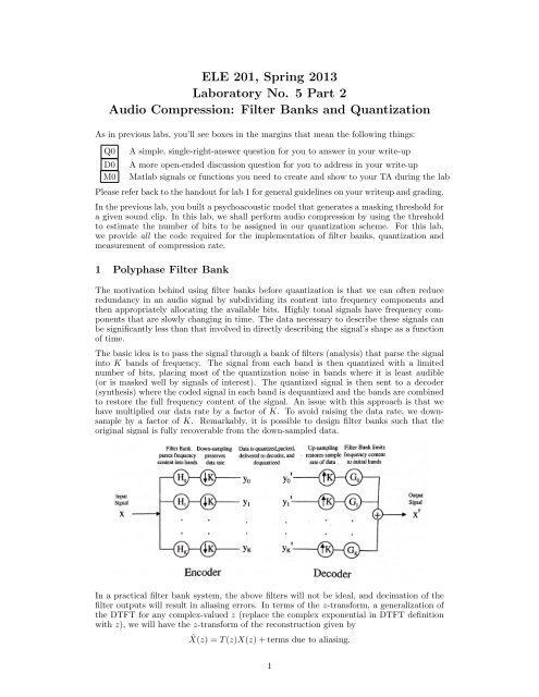
The basic idea is to pass the signal through a bank of filters (analysis) that parse the signal<br />
into K bands of frequency. The signal from each band is then quantized with a limited<br />
number of bits, placing most of the quantization noise in bands where it is least audible<br />
(or is masked well by signals of interest). The quantized signal is then sent to a decoder<br />
(synthesis) where the coded signal in each band is dequantized and the bands are combined<br />
to restore the full frequency content of the signal. An issue with this approach is that we<br />
have multiplied our data rate by a factor of K. To avoid raising the data rate, we downsample<br />
by a factor of K. Remarkably, it is possible to design filter banks such that the<br />
original signal is fully recoverable from the down-sampled data.<br />
Input<br />
Signaf<br />
x<br />
Filter Bank Down-sampling<br />
parses frequency preserves<br />
content into bands data rate<br />
Data is quantized,packed,<br />
delivered to decoder, and<br />
dequantized<br />
Yo<br />
t----- Yl<br />
• • •<br />
• • •<br />
1---- YK<br />
,.<br />
Yo ~---l<br />
Yl<br />
•<br />
,<br />
•<br />
,<br />
YK-- -4<br />
Up-sampling Filter Bank limits<br />
restores sample frequency content<br />
rate of data to initial bands ·<br />
•<br />
•<br />
•<br />
•<br />
Output<br />
Signal<br />
X'<br />
Encoder<br />
D,ecoder<br />
In a practical filter bank system, the above filters will not be ideal, and decimation of the<br />
filter outputs will result in aliasing errors. In terms of the z-transform, a generalization of<br />
the DTFT for any complex-valued z (replace the complex exponential in DTFT definition<br />
Generated by CamScanner from intsig.com<br />
with z), we will have the z-transform of the reconstruction given by<br />
ˆX(z) = T (z)X(z) + terms due to aliasing.<br />
1
If we can design the analysis and synthesis filters such that there are no aliasing terms and<br />
T (z) = c · z −k , where c is a constant and k ∈ N, then the system is said to have the perfect<br />
reconstruction (PR) property. This will ensure that the output of the system is the original<br />
signal delayed by k time-steps, up to rescaling (by c). We provide a PR filter bank for this<br />
lab, but we shall not discuss its construction here.<br />
In the provided file lab5 p2.m, we have included a routine to generate h and g, analysis and<br />
synthesis filter banks respectively, that constitute a PR system. There are 32 filters and the<br />
length of each one is 64, so that h is a 32 × 64 matrix. Verify that these filters partition the<br />
frequency spectrum - use the provided vector of frequencies f1. <strong>No</strong>te that the sum of the M1<br />
powers is flat across frequency. Explain how h relates to w.<br />
Q1<br />
Puzzle: Have you ever converted a .mp3 file to a .wav file? What you should observe is<br />
that the file size increases - sometimes by a factor as large as 10. We know that the .mp3<br />
file was compressed audio, while .wav is the format of choice for uncompressed audio. Why<br />
do we observe an increase in size - surely, there is no way to de-compress compressed audio?<br />
The .wav file cannot contain more interesting information that the .mp3 file did. Is .wav<br />
just an inherently inefficient format?<br />
Q2<br />
2 Quantization<br />
In the same file lab5 p2.m, we also provide code to create xQ, a quantized version of x -<br />
using b bits (2 ≤b≤ 16, since the original data rate is 16 bits/sample). In lecture, it was<br />
mentioned that the finer our quantization, the weaker will be the correlation between the<br />
error and the signal. The error (x-xQ) represents the amount of information lost. Ideally,<br />
we would like this error to resemble noise - so no relevant information is lost. Does the<br />
error sound like noise? What happens as you decrease/increase the number of bits used?<br />
What is the minimum number of bits for which the error sounds like noise? Is this behavior<br />
confirmed by the power spectrum of the noise?<br />
3 Implementation<br />
D1<br />
M2<br />
In the file encode.m, include a call to your psychoacoustic model to retrieve the masking<br />
threshold that will be used for compression. We have provided a bit assignment scheme in<br />
the file performEncoding.m. The functions keep track of the number of bits used - justify<br />
the definition of newbits in performEncoding.m.<br />
What is the compression ratio you see for the provided file test.wav? What happens<br />
when you use the ATH instead of the masking threshold? Can you use an alternative<br />
bit assignment to get a better compression rate? You may use knowledge of the center D2<br />
frequency in each filter of the filter bank and also tonal information about the signal from<br />
your psychoacoustic model. Does your bit assignment scheme work as well for compressing<br />
other audio files?<br />
D3<br />
{What do you observe when w (defined in encode.m) is the all 1’s vector? Do the filters still<br />
partition frequencies with sum of powers constant? Explain.} {Can you suggest additional<br />
techniques or modifications that would allow us to get higher rates of compression?} Alternatively,<br />
using your knowledge of sampling from class, can you come up with simple<br />
compression schemes that achieve similar compression rates with comparable quality?<br />
4 References<br />
• Introduction to Digital <strong>Audio</strong> Coding and Standards by M. Bosi and R. E. Goldberg<br />
• Psychoacoustics: Facts and Models by H. Fastl and E. Zwickler<br />
• Watermarking Systems Engineering: Enabling Digital Assets Security and Other<br />
Applications by M. Barni and F. Bartolini<br />
• WAVS <strong>Compression</strong> by A. Chen, N. Shehad, A. Virani and E. Welsh<br />
Q3<br />
Q4<br />
Q5<br />
D4<br />
2